EPR – Areva brochure
EPR – Areva brochure
EPR – Areva brochure

You also want an ePaper? Increase the reach of your titles
YUMPU automatically turns print PDFs into web optimized ePapers that Google loves.
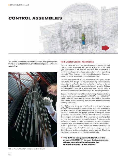
■ <strong>EPR</strong> NUCLEAR ISLANDCONTROL ASSEMBLIESThe control assemblies, inserted in the core through the guidethimblesof fuel assemblies, provide reactor power control andreactor trip.RCCA manufacturing at the FBFC Pierrelatte (France) fuel fabrication plant.Rod Cluster Control Assemblies†The core has a fast shutdown control system comprising 89 RodCluster Control Assemblies (RCCAs). All RCCAs are of the sametype and consist of 24 identical absorber rods, fastened to acommon head assembly. These rods contain neutron absorbingmaterials. When they are totally inserted in the core, they coveralmost the whole active length of the fuel assemblies.The <strong>EPR</strong> is equipped with RCCAs of the HARMONI type, a provenFramatome ANP design. The neutron absorbing components arebars made of an Ag, In, Cd alloy and sintered pellets of Boroncarbide (B4C). Each rod is composed of a stack of Ag, In, Cd barsand B4C pellets contained in a stainless steel cladding under aHelium atmosphere (for efficient cooling of the absorbing materials).Because mechanical wear of the rod claddings happens to be alimiting factor for the operating life of RCCAs, the HARMONIcladdings benefit from a specific treatment (ion-nitriding) that makestheir external surface extremely wear-resistant and eliminates thecladding wear issue.The RCCAs are assigned to different control bank groups.37 RCCAs are assigned to control average moderator temperatureand axial offset, and 52 RCCAs constitute the shutdown-bank. Thefirst set is divided into five groups split into quadruplets. Thesequadruplets are combined to form four different insertion sequencesdepending on cycle depletion. This sequence can be changed atany time during operation, even at full power. A changeover isperformed at regular intervals, approximately every 30 equivalentfull power days, to rule out any significant localized burnup delay.At rated power the control banks are nearly withdrawn. Atintermediate power level, the first quadruplet of a sequence can bedeeply inserted and the second may be also inserted. Shutdownmargins are preserved by the RCCA insertion limits.† The <strong>EPR</strong> is equipped with RCCAs of theproven HARMONI design that guaranteesa long operating life whatever theoperating mode of the reactor.Plug connectorUpperlimit positionindicator coilPosition indicator coilLower limitposition indicator coilLiftingPoleArmatureGripping ArmatureLatchLatch CarrierHoldingPoleLatch CarrierArmatureLatchFlange connectionSealing areaCRDM cutawayDriverodupperfinalpositionLiftingcoilGrippingcoilHoldingcoilControl Rod Drive MechanismsPWRControl RodMechanism(CRDM)Sheet steelcasingDrive rodlower finalpositionCRDMnozzleA function of the Control Rod Drive Mechanisms (CRDMs), forreactor control purposes, is to insert and withdraw the 89 RCCAsover the entire height of the core and to hold them in any selectedposition. The other function of the CRDMs is to drop the RCCAsinto the core, to shut down the reactor in a few seconds by stoppingthe chain reaction, in particular in case of an abnormal situation.The CRDMs are installed on the reactor pressure vessel head andfixed to adapters welded to the vessel head. Each CRDM is a selfcontainedunit that can be fitted or removed independently of theothers. These CRDMs do not need forced ventilation of the coils,which saves space on the reactor head. The control rod drive systemresponds to the actuation signals generated by the reactor controland protection system or by operator action. The pressure housingsof the CRDMs are part of the second of the three barriers againstradioactive releases, like the rest of the reactor primary circuit.Therefore, they are designed and fabricated in compliance with thesame level of quality requirements.CHARACTERISTICSDATARod cluster control assemblies (RCCAs)Mass82.5 kgNumber of rods per assembly 24AbsorberAIC part (lower part)<strong>–</strong> Weight composition (%): Ag, In, Cd 80, 15, 5<strong>–</strong> Specific mass 10.17 g/cm 3<strong>–</strong> Absorber outer diameter 7.65 mm<strong>–</strong> Length 1,500 mmB4C part (upper part)<strong>–</strong> Natural Boron 19.9% atoms of B 10<strong>–</strong> Specific mass 1.79 g/cm 3<strong>–</strong> Absorber diameter 7.47 mm<strong>–</strong> Length 2,610 mmCladdingMaterialAISI 316 stainless steelSurface treatment (externally)Ion-nitridingOuter diameter9.68 mmInner diameter7.72 mmFilling gasHeliumControl rod drive mechanisms (CRDMs)Quantity 89Mass403 kgLift force> 3,000 NTravel range4,100 mmStepping speed375 mm/min or 750 mm/minMax. scram time allowed3.5 sMaterials<strong>–</strong> Forged Z5 CN 18-10 stainless steel<strong>–</strong> Magnetic Z12 C13<strong>–</strong> Amagnetic stainless steelThe complete CRDM consists of:• the pressure housing with flange connection,• the latch unit,• the drive rod,• the coil housing.When the reactor trip signal is given, all operating coils are deenergized,the latches are retracted from the rod grooves and theRCCA drops freely into the reactor core under the force of gravity.† CRDMs are of the same type as thoseused in the KONVOI reactors, thus theyare well proven and based on excellenttrack record.† CRDMs are latch mechanisms cooledby natural convection which saves spaceon the reactor head.20 II 21