EPR – Areva brochure
EPR – Areva brochure
EPR – Areva brochure

You also want an ePaper? Increase the reach of your titles
YUMPU automatically turns print PDFs into web optimized ePapers that Google loves.
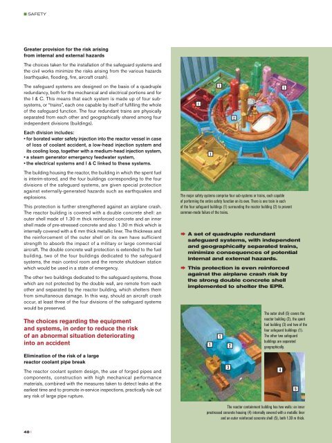
■ SAFETYGreater provision for the risk arisingfrom internal and external hazardsThe choices taken for the installation of the safeguard systems andthe civil works minimize the risks arising from the various hazards(earthquake, flooding, fire, aircraft crash).The safeguard systems are designed on the basis of a quadrupleredundancy, both for the mechanical and electrical portions and forthe I & C. This means that each system is made up of four subsystems,or “trains”, each one capable by itself of fulfilling the wholeof the safeguard function. The four redundant trains are physicallyseparated from each other and geographically shared among fourindependent divisions (buildings).Each division includes:• for borated water safety injection into the reactor vessel in caseof loss of coolant accident, a low-head injection system andits cooling loop, together with a medium-head injection system,•a steam generator emergency feedwater system,• the electrical systems and I & C linked to these systems.The building housing the reactor, the building in which the spent fuelis interim-stored, and the four buildings corresponding to the fourdivisions of the safeguard systems, are given special protectionagainst externally-generated hazards such as earthquakes andexplosions.This protection is further strengthened against an airplane crash.The reactor building is covered with a double concrete shell: anouter shell made of 1.30 m thick reinforced concrete and an innershell made of pre-stressed concrete and also 1.30 m thick which isinternally covered with a 6 mm thick metallic liner. The thickness andthe reinforcement of the outer shell on its own have sufficientstrength to absorb the impact of a military or large commercialaircraft. The double concrete wall protection is extended to the fuelbuilding, two of the four buildings dedicated to the safeguardsystems, the main control room and the remote shutdown stationwhich would be used in a state of emergency.The other two buildings dedicated to the safeguard systems, thosewhich are not protected by the double wall, are remote from eachother and separated by the reactor building, which shelters themfrom simultaneous damage. In this way, should an aircraft crashoccur, at least three of the four divisions of the safeguard systemswould be preserved.The choices regarding the equipmentand systems, in order to reduce the riskof an abnormal situation deterioratinginto an accident1112The major safety systems comprise four sub-systems or trains, each capableof performing the entire safety function on its own. There is one train in eachof the four safeguard buildings (1) surrounding the reactor building (2) to preventcommon-mode failure of the trains.† A set of quadruple redundantsafeguard systems, with independentand geographically separated trains,minimize consequences of potentialinternal and external hazards.† This protection is even reinforcedagainst the airplane crash risk bythe strong double concrete shellimplemented to shelter the <strong>EPR</strong>.1121The outer shell (5) covers thereactor building (2), the spentfuel building (3) and two of thefour safeguard buildings (1).The other two safeguardbuildings are separatedgeographically.Optimized management ofaccidental steam generator tube breakSteam generator tube break is an accident which, if it occurs, leadsto a transfer of water and pressure from the primary system to thesecondary system. The primary side pressure drop automaticallyinduces a reactor shutdown then, if a given pressure threshold isreached, the activation of the safety injection of water into the reactorvessel. The choice, for the <strong>EPR</strong>, of a safety injection pressure(medium-head injection) lower than the set pressure of the secondarysystem safety valves prevents the steam generators from filling upwith water in such a case. This has a dual advantage: it avoids theproduction of liquid releases and considerably reduces the risk of asecondary safety valve locking in open position.Simplification of the safety systems and optimizationof their redundancy and diversificationThe safety-important systems and their support systems are <strong>–</strong> asalready set out <strong>–</strong> quadrupled, each featuring four trains sharedamong four separate divisions.The structure of these systems is straightforward and minimizes thechanges that have to be made to their configuration depending onwhether the reactor is at power or in shutdown; the design of the<strong>EPR</strong> safety injection system and residual heat removal system is anillustration of this.The safety injection system, which would be activated in case of aloss of coolant accident, is designed to inject water into the reactorcore to cool it down. In a first phase, water would be injected into thecore via the cold legs of the reactor coolant system loops (legslocated between the reactor coolant pumps and the reactor vessel).In the longer term, the water would be simultaneously injected via thecold and hot legs (legs located between the steam generators andthe reactor vessel). The water reserve intended to feed the safetyinjection system is located on the inside and at the bottom of thereactor containment, and the injection pumps only take suction fromthis reserve. Therefore, there is no need (compared to previousdesigns) for switching over from a so-called “direct injection” phaseto a “recirculation” phase. The <strong>EPR</strong> safety injection system isequipped with heat exchangers in its low-head portion, to be capableof ensuring core cooling on its own. The <strong>EPR</strong> is further equippedwith a severe accident dedicated system for cooling the inside ofthe reactor containment, which would be only activated in theeventuality of an accident leading to core melt.Residual heat removal is provided by the four trains of the low headportion of the safety injection system, which are then configured toremove the residual heat in closed loop (suction via the hot legs,discharge via the cold legs). Safety injection remains available foraction in the eventuality of a leak or break occurring on the reactorcoolant system.† The safety-related systems are simple,redundant and diversified to ensurereliability and efficiency.Increased reliability of operator actionExtension of action times available to the operatorThe protection and safeguard actions needed in the short term inthe eventuality of an incident or accident are automated. Operatoraction is not required before 30 minutes for an action taken in thecontrol room, or one hour for an action performed locally on the plant.The increase in the volumes of the major components (reactorpressure vessel, steam generators, pressurizer) gives the reactorextra inertia which helps to extend the time available to the operatorsto initiate the first actions.Increased performance of the Man-Machine InterfaceThe progress accomplished in the digital I & C field and the analysisof the experience feedback from the design and operation of the N4reactors, among the first plants to be equipped with a fullycomputerizedcontrol room, have conferred on the <strong>EPR</strong> a highperformance,reliable and optimized solution in terms of Man-MachineInterface. The quality and relevance of the summary data on thereactor and plant status made available in real time to the operatorsfurther boost the reliability of their actions.Elimination of the risk of a largereactor coolant pipe breakThe reactor coolant system design, the use of forged pipes andcomponents, construction with high mechanical performancematerials, combined with the measures taken to detect leaks at theearliest time and to promote in-service inspections, practically rule outany risk of large pipe rupture.3The reactor containment building has two walls: an innerprestressed concrete housing (4) internally covered with a metallic linerand an outer reinforced concrete shell (5), both 1.30 m thick.45Computer-generated image of the <strong>EPR</strong> control room.† Design of components, high degree ofautomation, advanced solutions for I & Cand Man-Machine Interface combineto further add to reliability of operatoractions.48 II 49