EPR – Areva brochure
EPR – Areva brochure
EPR – Areva brochure

You also want an ePaper? Increase the reach of your titles
YUMPU automatically turns print PDFs into web optimized ePapers that Google loves.
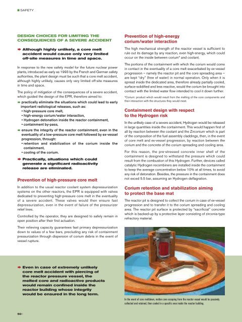
■ SAFETYDESIGN CHOICES FOR LIMITING THECONSEQUENCES OF A SEVERE ACCIDENT† Although highly unlikely, a core meltaccident would cause only very limitedoff-site measures in time and space.In response to the new safety model for the future nuclear powerplants, introduced as early as 1993 by the French and German safetyauthorities, the plant design must be such that a core melt accident,although highly unlikely, causes only very limited off-site measuresin time and space.The policy of mitigation of the consequences of a severe accident,which guided the design of the <strong>EPR</strong>, therefore aimed to:† practically eliminate the situations which could lead to earlyimportant radiological releases, such as:• high-pressure core melt,• high-energy corium/water interaction,• Hydrogen detonation inside the reactor containment,• containment by-pass,† ensure the integrity of the reactor containment, even in theeventuality of a low-pressure core melt followed by ex-vesselprogression, through:• retention and stabilization of the corium inside thecontainment,• cooling of the corium.† Practically, situations which couldgenerate a significant radioactivityrelease are eliminated.Prevention of high-pressure core meltIn addition to the usual reactor coolant system depressurizationsystems on the other reactors, the <strong>EPR</strong> is equipped with valvesdedicated to preventing high-pressure core melt in the eventualityof a severe accident. These valves would then ensure fastdepressurization, even in the event of failure of the pressurizerrelief lines.Controlled by the operator, they are designed to safely remain inopen position after their first actuation.Prevention of high-energycorium/water interactionThe high mechanical strength of the reactor vessel is sufficient torule out its damage by any reaction, even high-energy, which couldoccur on the inside between corium* and coolant.The portions of the containment with which the corium would comein contact in the eventuality of a core melt exacerbated by ex-vesselprogression <strong>–</strong> namely the reactor pit and the core spreading area <strong>–</strong>are kept “dry” (free of water) in normal operation. Only when it isspread inside the dedicated area, therefore already partially cooled,surface-solidified and less reactive, would the corium be brought intocontact with the limited water flow intended to cool it down further.*Corium: product which would result from the melting of the core components andtheir interaction with the structures they would meet.Containment design with respectto the Hydrogen riskIn the unlikely case of a severe accident, Hydrogen would be releasedin large quantities inside the containment. This would happen first ofall by reaction between the coolant and the Zirconium which is partof the composition of the fuel assembly claddings, then, in the eventof core melt and ex-vessel progression, by reaction between thecorium and the concrete of the corium spreading and cooling area.For this reason, the pre-stressed concrete inner shell of thecontainment is designed to withstand the pressure which couldresult from the combustion of this Hydrogen. Further, devices calledcatalytic Hydrogen recombiners are installed inside the containmentto keep the average concentration below 10% at all times, to avoidany risk of detonation. Besides, the pressure in the containment doesnot exced 5.5 bar, assuming an Hydrogen deflagration.Corium retention and stabilization aimingto protect the base matThe reactor pit is designed to collect the corium in case of ex-vesselprogression and to transfer it to the corium spreading and coolingarea. The reactor pit surface is protected by “sacrificial” concretewhich is backed-up by a protective layer consisting of zirconia-typerefractory material.The dedicated corium spreading and cooling area is a core-catcherequipped with a solid metal structure and covered with “sacrificial”concrete. It aims to protect the nuclear island basemat from anydamage, its lower section features cooling channels in which watercirculates. The aim of its large spreading surface area (170 m 2 ) is topromote the cooling of the corium.The transfer of the corium from the reactor pit to the spreading areawould be initiated by a passive device: a steel “plug” melting underthe effect of the heat from the corium.After spreading, the flooding of the corium would also be initiated bya passive fusible plug-based device. It would then be cooled, stillpassively, by gravity injection of water from the tank located inside thecontainment and by evaporation.The effectiveness of the cooling would then provide stabilization of thecorium in a few hours and its complete solidification in a few days.Containment heat removal systemand long-term residual heat removal deviceIn the eventuality of a severe accident, to prevent the containmentfrom losing its long-term integrity, means would have to be providedto control the pressure inside the containment and to stop it fromrising under the effect of residual heat. A dedicated dual-train spraysystem with heat-exchangers and dedicated heat sink is providedto fulfil this function. A long time period would be available for thedeployment of this system by the operators: at least 12 hours owingto the large volume of the containment (80,000 m 3 ).Containment heat removal systemA second mode of operation of the containment heat removal systemenables to feed water directly into the core-catcher, instead of intothe spray system.Collection of inter-containment leaksIn the eventuality of a core melt leading to vessel failure, thecontainment remains the last of the three containment barriers; thismeans that provisions must be taken to make sure that it remainsundamaged and leak-tight. For the <strong>EPR</strong>, the following measures havebeen adopted:•a 6 mm thick metal liner internally covers the pre-stressed concreteinner shell,• the internal containment penetrations are equipped with redundantisolation valves and leak recovery devices to avoid any containmentbypass,• the architecture of the peripheral buildings and the sealing systemsof the penetrations rule out any risk of direct leakage from the innercontainment to the environment,• the space between the inner and outer shells of the containment ispassively kept at slight negative pressure to enable the leaks tocollect there,• these provisions are supplemented by a containment ventilationsystem and a filter system upstream of the stack.Spray nozzlesTheir relieving capacity guarantees fast primary depressurizationdown to values of a few bars, precluding any risk of containmentpressurization through dispersion of corium debris in the event ofvessel rupture.xxPassivefloodingdevicex† Even in case of extremely unlikelycore melt accident with piercing ofthe reactor pressure vessel, themelted core and radioactive productswould remain confined inside thereactor building whose integritywould be ensured in the long term.In the event of core meltdown, molten core escaping from the reactor vessel would be passivelycollected and retained, then cooled in a specific area inside the reactor building.CHRS(2x)Coriumspreading areaMelt flooding via cooling deviceand lateral gapIn-containment refuelingwater storage tankxWater level in case of waterinjection into spreading areaFL Flow limiter50 II 51