EPR – Areva brochure
EPR – Areva brochure
EPR – Areva brochure

You also want an ePaper? Increase the reach of your titles
YUMPU automatically turns print PDFs into web optimized ePapers that Google loves.
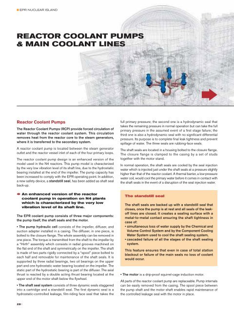
■ <strong>EPR</strong> NUCLEAR ISLANDREACTOR COOLANT PUMPS& MAIN COOLANT LINES†Reactor coolant pump cutaway123CHARACTERISTICSDATAReactor coolant pumpsNumber 4Overall height9.3 mOverall mass w/o water and oil112 tPumpDesign pressure176 barDesign temperature 351 °CDesign flow rate 28,330 m 3 /hDesign manometric head 100.2 m ± 5%Seal water injection 1.8 m 3 /hSeal water return 0.680 m 3 /hSpeed1,485 rpmMotorRated power9,000 kWFrequency50 HzReactor Coolant PumpsThe Reactor Coolant Pumps (RCP) provide forced circulation ofwater through the reactor coolant system. This circulationremoves heat from the reactor core to the steam generators,where it is transferred to the secondary system.A reactor coolant pump is located between the steam generatoroutlet and the reactor vessel inlet of each of the four primary loops.The reactor coolant pump design is an enhanced version of themodel used in the N4 reactors. This pump model is characterizedby the very low vibration level of its shaft line, due to the hydrostaticbearing installed at the end of the impeller. The pump capacity hasbeen increased to comply with the <strong>EPR</strong> operating point. In addition,a new safety device, a standstill seal, has been added as shaft sealback-up.† An enhanced version of the reactorcoolant pump in operation on N4 plantswhich is characterized by the very lowvibration level of its shaft line.The <strong>EPR</strong> coolant pump consists of three major components:the pump itself, the shaft seals and the motor.• The pump hydraulic cell consists of the impeller, diffuser, andsuction adapter installed in a casing. The diffuser, in one piece, isbolted to the closure flange. The whole assembly can be removed inone piece. The torque is transmitted from the shaft to the impeller bya “Hirth” assembly which consists in radial grooves machined onthe flat end of the shaft and symmetrically on the impeller. The shaftis made of two parts rigidly connected by a “spool” piece bolted toeach half and removable for maintenance of the shaft seals. It issupported by three radial bearings, two oil bearings on the upperpart and one hydrostatic water bearing located on the impeller. Thestatic part of the hydrostatic bearing is part of the diffuser. The axialthrust is reacted by a double acting thrust bearing located at theupper end of the motor shaft below the flywheel.• The shaft seal system consists of three dynamic seals staggeredinto a cartridge and a standstill seal. The first dynamic seal is ahydrostatic-controlled leakage, film-riding face seal that takes thefull primary pressure; the second one is a hydrodynamic seal thattakes the remaining pressure in normal operation but can take the fullprimary pressure in the assumed event of a first stage failure; thethird one is also a hydrodynamic seal with no significant differentialpressure. Its purpose is to complete final leak tightness and preventspillage of water. The three seals are rubbing-face seals.The shaft seals are located in a housing bolted to the closure flange.The closure flange is clamped to the casing by a set of studstogether with the motor stand.In normal operation, the shaft seals are cooled by the seal injectionwater which is injected just under the shaft seals at a pressure slightlyhigher than that of the reactor coolant. A thermal barrier, a low-pressurewater coil, would cool the primary water before it comes in contact withthe shaft seals in the event of a disruption of the seal injection water.The standstill sealThe shaft seals are backed up with a standstill seal thatcloses, once the pump is at rest and all seals of the leakofflines are closed. It creates a sealing surface with ametal-to-metal contact ensuring the shaft tightness incase of:• simultaneous loss of water supply by the Chemical andVolume Control System and by the Component CoolingWater System used to cool the shaft sealing system,• cascaded failure of all the stages of the shaft sealingsystem.This feature ensures that even in case of total stationblackout or failure of the main seals no loss of coolantwould occur.• The motor is a drip-proof squirrel-cage induction motor.All parts of the reactor coolant pump are replaceable. Pump internalscan be easily removed from the casing. The spool piece betweenthe pump shaft and the motor shaft enables rapid maintenance ofthe controlled leakage seal with the motor in place.418621227891011216191451517131 Flywheel2 Radial bearings3 Thrust bearing4 Air cooler5 Oil cooler6 Motor (stator)7 Motor (rotor)8 Motor shaft9 Spool piece10 Pump shaft11 Shaft seal housings12 Main flange13 Seal water injection14 Thermal barrier heat exchanger15 Diffuser16 Impeller17 Pump casing18 Discharge19 Suction28 II 29