MOUNTING & DEMOUNTING SAFETY INFORMATION - Titan
MOUNTING & DEMOUNTING SAFETY INFORMATION - Titan
MOUNTING & DEMOUNTING SAFETY INFORMATION - Titan
- No tags were found...

Create successful ePaper yourself
Turn your PDF publications into a flip-book with our unique Google optimized e-Paper software.
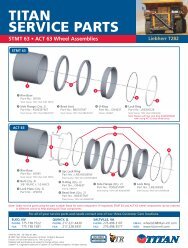
<strong>MOUNTING</strong> &DE<strong>MOUNTING</strong> <strong>SAFETY</strong><strong>INFORMATION</strong>
<strong>Titan</strong> Tire Corporation www.titanstore.com 1.800.USA.BEARSafety InformationWARNINGThe task of servicing tires and wheels can be extremely dangerous andshould be performed by trained personnel only, using the correct tools andfollowing specific procedures. Failure to heed this warning could lead toserious injury or death. Read and understand the “Safety Information” inthis catalog. We urge that the following is mandatory reading for all thoseinvolved in the servicing of tires and wheels:Department of Labor Occupation Safety and Health Administration (OSHA)29 CFR part 1910.177, titled Servicing of Single Piece and Multi-piece RimWheels. NOTE: Single piece rims have a rim made out of a single pieceof material as shown on page S-20 and multiple-piece rims have a looseflange or flanges and lock ring as depicted on pages S-20 and S-21.Rubber Manufacturers Association, “Care and Service of Farm Tires.”Rubber Manufacturers Association, “Care and Service of Off-the-Highway Tires.”Rubber Manufacturers Association, “Care and Service of HighwayTruck Tires.”Rubber Manufacturers Association, “Demounting and MountingProcedure Wall Charts:Automobile and Light Truck Tires on Single piece RimsTruck Tires (Radial and Bias ply)Truck/Bus TiresAgricultural TiresWe have shown step by step procedures for the servicing of single piece,three piece and five piece rims with the emphasis on safety operations forthese rims in this catalog. Information on other types of rims can be found inthe above RMA publications or in the catalogs published by the rim manufacturer.This and any other safety related information in <strong>Titan</strong>’s catalog isissued as assistance to supervisory and operational personnel in the actualtire/rim service environment. The responsibility for implementation of thissafety information rests with operational and supervisory personnel carryingout the actual service work. Read and fully understand all proceduresbefore attempting tire/wheel servicing.If you have any doubt about the correct, safe method of performingany step in the demounting, mounting, adding or removing fill, orinflating process STOP! Seek out expert assistance from a qualified person.Wear protective gloves, footwear, safety glasses, hearing protection andhead gear when servicing tires and wheels.Further references explaining safety procedures can be found in literaturepublished by the Rubber Manufacturers Association, Washington D.C.; theTire Association of North America, Washington D.C.; the National Wheeland Rim Association, Jacksonville, FL; and OSHA, Washington D.C.<strong>SAFETY</strong> FIRST!S-1
1.800.USA.BEAR www.titanstore.com <strong>Titan</strong> Tire CorporationSafety InformationIMPORTANT!THIS IS THE FIRST STEP IN ALLDE<strong>MOUNTING</strong> OPERATIONSAlways remove the valve core and exhaust all air from asingle tire and from both tires of a dual assembly. Checkthe valve stem by running a piece of wire through the stem tomake sure it is not plugged.READ AND FOLLOW <strong>SAFETY</strong> INSTRUCTIONS.FAILURE TO DO SO COULD RESULT IN SERIOUSINJURY.Removing valve core fromagricultural wheel.Running wire through the stem of anagricultural wheel.S-2
<strong>Titan</strong> Tire Corporation www.titanstore.com 1.800.USA.BEARGENERAL WARNINGSSafety InformationThis symbol indicates a warning message.Failure to heed warnings could lead to serious injury or death.• The task of servicing tires and wheels can be extremely dangerous andshould be performed by trained personnel only, using the correct tools,and following the procedures presented here and in manufacturers’ catalogs,instruction manuals, or other industry and government instructionmaterial.• Several types of tire changing equipment are available. Installers shouldbe fully trained in correct operating procedures and safety instructionsfor the specific machine being used. Always read and understand anymanufacturer’s warning contained in the product literature or posted onthe equipment.• Always use approved tire and rim combinations for sizes and contours.• Always wear personal protection equipment such as gloves, footwear,eye protection, hearing protection and head gear, when servicing tire andwheels.• Never exceed manufacturer’s recommended tire inflation pressure.• Always use proper lifting techniques, and mechanized lifting aids to moveheavy components and assemblies.• Parts that are cracked, worn, pitted with corrosion, or damaged must bedestroyed, discarded, and replaced with good parts.• Always exhaust all air from the tire prior to demounting.• Never try to repair wheel, rim, or tire component parts. Replace all damaged,worn, or suspect parts with good parts.• Never reinflate a tire that has lost air pressure or has been reinflated withoutdetermining and correcting its problem.• When conducting routine tire inspections also conduct a visual inspectionof wheel and rim components. Always correct any non-conformities found.• Always use restraining devices (safety cages) when inflating tires.• Never exceed 35 psi when seating beads.• Misapplication, improper inflation, overloading, and exceeding maximumspeed may cause tire failure.• Always inspect both sides of the tire to assure proper bead seat.• Always take care when moving tires and wheels that other people in thearea are not endangered.• Never leave a tire, wheel, or assembly unsecured in a vertical position.S-3
1.800.USA.BEAR www.titanstore.com <strong>Titan</strong> Tire CorporationSafety InformationGENERAL WARNINGSWARNINGWARNING15.3” DIAMETER: 9” WIDTH EUROPEAN RIMSCertain European farm implement equipment has been imported intoNorth America with unique diameter rims for which no North Americanproduced replacement tire sizes are available.Any attempt to mount and inflate 15” nominal bead diameter tires onthese rims may ultimately cause one of the tire beads to break, possiblyresulting in serious physical injury or even death.The rims in question are 15.3” in diameter and 9” wide. However, rimsmanufactured in 1981 and earlier are marked as 15” diameter; onlythose manufactured in 1982 and 1983 are marked as 15.3” diameter.The key to avoiding this potentially dangerous situation is the 9”width. The U.S.A. (or Canada) wheel industry does not manufacture a9” width rim for farm implement use.There is a danger of serious injury or death if a tire of one bead diameteris installed on a rim or wheel of a different rim diameter.Always replace a tire with another tire of exactly the same bead diameterdesignation and suffix letters. For example: A 16” tire goes on a 16” rim.Never mount a 16” tire on a 16.1” or 16.5” rim. A 16.5” tire goes on a16.5” rim. Never mount a 16.5” tire on a 16” or 16.1” rim.While it is possible to pass a 16” diameter tire over the lip or flange of a16.1” or 16.5” size diameter rim, it cannot be inflated enough to positionitself against the rim flange. If an attempt is made to seat the tire beadby inflating, the tire bead will break with explosive force and could causeserious injury or death.Rims of different diameters and tapers cannot be interchanged. Thefollowing diagram illustrates the difference between rims of two differenttapers and diameters:The European tires sizes that may be mounted on these rims are:10.0/75 – 15.3 (or 15)10.5/85 – 15.311.5/80 – 15.3 (or 15)12.5/80 – 15.3U.S.A. (OR CANADA) PRODUCED FARM IMPLEMENT TIRES ARENOT TO BE MOUNTED ON ANY 9” WIDE FARM IMPLEMENT RIM.The following diagram shows how beads of a 16” tire will not seat on a 16.5”rim. The beads cannot be forced out against the rim flanges by using moreair pressure because this will break the beads and the tire will explode withforce sufficient to cause serious injury or death.S-4
<strong>Titan</strong> Tire Corporation www.titanstore.com 1.800.USA.BEARGENERAL WARNINGSSafety InformationWARNINGSTAY OUT OF THE TRAJECTORY AS INDICATED BY SHADEDAREA. ALWAYS USE A <strong>SAFETY</strong> CAGE OR OTHER RESTRAININGDEVICE IN COMPLIANCE WITH OSHA REGULATIONS.Note: Under some circumstances, the trajectory may deviate from itsexpected path.TO DETERMINE COMPATIBLE RIM WIDTHFOR TIRE SIZESDetermine the vehicle’s actual rim width by measuring, in inches,the distance between the vertical bead flanges as shown. A simpleruler or yardstick may be used, as rims are manufactured in half inchincrements of width.Find permissible replacement tire sizes in RMA’s Care and ServiceTires Manual (Washington, D.C.). Most tires will fit on more than onerim width.NEVER stand, lean or reach over the assembly during inflation.S-5
1.800.USA.BEAR www.titanstore.com <strong>Titan</strong> Tire CorporationSafety InformationDemounting Agricultural Wheel and Tire Assemblies(On-The-Vehicle)Tools Required: Cap and coreremoval tools, bead unseating tool,two 36” tire irons, two 18” tire irons,vegetable-based lubricant.If you have any doubt aboutthe correct, safe method ofperforming any step in the demounting,mounting, adding or removingfill, or inflating process STOP! Seekout expert assistance from a qualifiedperson.Due to the variety of vehicle/equipment configurationsand the range of conditions andsituations under which on-vehicledemounting (wheel/tire assemblystill attached to vehicle or equipment)can occur, proper proceduresfor blocking, jacking, cribbing of thevehicle/ equipment must be donein accordance with the manufacturersoperator’s manual, maintenancemanual or the information asprovided by the vehicle/equipmentmanufacturer.Tools required: Jack, cribbing,blocking or other items as neededto jack and block the vehicle/equipmentper the manufacturers instructions,hydraulic demounting tool,hooked tire iron, pry bar and liftingdevice or boom truck.1. Remove the fluid fill from the tire.Deflate the tire by removing thevalve core housing. For tube-typetires, remove the rim nut and pushthe valve through the valve hole.Always completely deflatetire (both tires of a dual assembly)by removing valve core(s)from valve(s) before attempting anydemounting operation. Check thevalve stem by running a piece ofwire through the stem to make sureit is not plugged.Stand clear of trajectory dangerzone when deflating (pageS-5).2. After the tire is completely deflated,place a hydraulic “bead unseating”tool between the tire bead andrim flange and force the bead off thebead seat. Be careful not to damagethe tire’s bead area. The beadsshould be unseated on both sides ofthe rim.Demounting tools apply pressureto rim flanges to unseattire beads. Keep your fingers clear.Always stand to one side when youapply hydraulic pressure.3. Thoroughly lubricate the tire beadarea and rim flange with a vegetable-basedlubricant.Never use a petroleum-basedlubricant. Only use vegetablebasedlubricant.4. Lock the wheel with the valveat the top. At the bottom, force theoutside bead into the well. At thetop, insert long tire irons under thebead and pry the bead over the rimflange. Take small bites and avoidextremely hard prying, which willdamage the tire bead.Do not release your grip oneither iron, as they may springback.Keep fingers clear of pinchpoints.5. After the first section of the beadis over the rim flange, use one tireiron to pry the next section over theflange. Do not attempt to pry toolarge a section of the bead over therim flange at one time. Continueprying tire over rim flange until thecomplete tire is on the outside of therim flange.S-6
<strong>Titan</strong> Tire Corporation www.titanstore.com 1.800.USA.BEARSafety InformationDemounting Agricultural Wheel and Tire Assemblies(On-The-Vehicle)Tools Required: Cap and coreremoval tools, bead unseating tool,two 36” tire irons, two 18” tire irons,vegetable-based lubricant.If you have any doubt aboutthe correct, safe method ofperforming any step in the demounting,mounting, adding or removingfill, or inflating process STOP! Seekout expert assistance from a qualifiedperson.Do not release your grip oneither iron, as they may springback.Keep fingers clear of pinchpoints.6. For tube-type tires, pull the tubeout of the casing, starting at thebottom. If only the tube requiresrepair or replacement, this can beremoved, repaired, and replacedin the tire without removing the tirecompletely from the wheel. Beforereinstalling the tube, thoroughlyinspect the inside of the casing fordamage or other foreign material.Remove any remaining fluid frominside the tire.Tires or tubes with excessiveor uneven wear, cracks, tears,punctures, blisters and or otherdamage may explode during inflationor service. If tire or tube failurepotential is suspected, destroy thetire and replace with known goodtire or tube of correct size, type andmanufacturer for assembly, machine,and application.7. To remove the tire completelyfrom the wheel, insert tire irons underthe inside bead at the side of thetire. Pry the rest of the inside beadover the rim flange. When startingthis operation, be sure that the beadarea on the opposite side of the tireis down in the well of the rim.Do not release your grip oneither iron, as they may springback.Keep fingers clear of pinchpoints.S-7
1.800.USA.BEAR www.titanstore.com <strong>Titan</strong> Tire CorporationSafety InformationMounting Agricultural Wheel and Tire Assemblies(On-The-Vehicle)Tools Required: vegetable-basedlubricant, wire brush, two 36” tireirons, two 18” tire irons, rubbermallet, extension hose with in-linegauge and clip-on air chuck, air/water inflation gauge, restrainingdevice.directional bead tires are mountedfor correct rotation direction.If you have any doubt in thecorrect, safe method of performingany step in the demounting,mounting, adding or removing fill, orinflating process STOP! Seek outexpert assistance from a qualifiedperson.ALWAYS replace a tire on arim with another tire of exactlythe same rim diameter designation.Rims of different diametersand tapers CANNOT be interchanged.Remove water and foreign materialfrom tire. Tubes or tireswith excessive wear, cracks, tears,punctures, blisters, or other damagemay explode during inflation or service.If tube or tire failure potentialis suspected, render the tube or tireunusable and replace with knowngood tube or tire.1. Thoroughly lubricate the tire beadarea and rim flange with a vegetable-basedlubricant.Never use petroleum-basedlubricant. Only use vegetablebasedlubricant.2. With a wire brush, clean and inspectrim for fatigue cracks. Replaceany cracked, badly worn, damagedand severely rusted rims or wheels.Coat the rim with paint or a rustinhibitor if necessary.Follow procedures and safetyprecautions of the paint manufacturer.Do not, under any circumstances,attempt to rework,weld, heat, or braze any rim base orwheel components.3. Before placing tire on rim, be surethe rim’s valve hole is at the bottomof wheel. Also take care to ensure4. To put the tire on the wheel, placethe inner bead over the flange at thetop. Be sure the bead is not “hungup” on the bead seat, instead thebead is guided into the rim well,while the tire irons and/or rubbermallet are used to work the firstbead over the rim. With the firstbead on the rim, pull the tire towardthe outside of the rim as far as possibleto make room for the tube.Keep fingers clear of pinchpoints.Keep a firm grip on the tireiron(s), as they may springback.5. Tubeless-type tires, skip to stepseven. For tube-type tires, be surethe valve is at the bottom of thewheel. Align the stem with the valvehole and starting at the bottom,place the tube in the tire. Place thevalve in valve hole and screw therim nut in place. Be sure that thetube is well inside the rim beforeproceeding to the next step.S-8
<strong>Titan</strong> Tire Corporation www.titanstore.com 1.800.USA.BEARSafety InformationMounting Agricultural Wheel and Tire Assemblies(On-The-Vehicle)Tools Required: vegetable-basedlubricant, wire brush, two 36” tireirons, two 18” tire irons, rubbermallet, extension hose with in-linegauge and clip-on air chuck, air/water inflation gauge, restrainingdevice.If you have any doubt in thecorrect, safe method of performingany step in the demounting,mounting, adding or removing fill, orinflating process STOP! Seek outexpert assistance from a qualifiedperson.6. In tube-type tires, the tube shouldbe partially inflated and areas thatcontact the rim should be relubricatedto prevent localized stretching.Never use petroleum-basedlubricant. Only use vegetablebasedlubricant.Keep fingers clear of pinchpoints.7. Starting at the top, use the tireirons to lift the outer bead up andover the rim flange, then down intothe rim well. Be careful not to pinchthe tube in this operation.Keep fingers clear of pinchpoints.Do not release your grip oneither iron, as they may springback.8. After getting the first section ofthe outer bead into the rim well,remove the tire iron and place onehand against that section to holdit in then pry the remainder of thebead over the flange with the tireiron in the other hand.Keep fingers clear of pinchpoints.Keep firm grip on tire iron(s),as they may spring back.9. With the valve stem at the bottom,lower the jack until the tire is centeredon the rim. Centering of thetire and rim assembly is extremelyimportant to prevent broken beads.10. Place a safety restraint overthe rim and tire. Using an extensionhose with an in-line air gaugeand clip-on chuck (with valve coreremoved), inflate the tire to seat thebeads. Do not exceed 35 psi. Checkfor correct concentric centering oftire on rim.For tubeless tires, successfulmounting depends on how well theshape of the tire has been maintained.If the beads are in or neartheir molded position, they can beseated by inflating the tire, throughthe valve spud. Where the beadshave been squeezed together, theuse of an inflator ring (either horizontallyor vertically) will be requiredto provide a seal between the tirebead and rim.If assembly is incorrect,– STOP – DEFLATE– CORRECT THE ASSEMBLY– repeat procedure.11. Raise the vehicle and rotatewheel assembly to have the valveat the top. If the tire is tube-type,completely deflate by removing thevalve core housing to remove bucklesand uneven stresses from thetube and flap before reinflation.12. If assembly is correct, re-insertthe valve core (for tube-type tires)and continue to inflate to recommendpressure.If assembly is incorrect– STOP – DEFLATE– CORRECT THE ASSEMBLY– repeat procedure.Stand clear of trajectory dangerzone when inflating (pageS-5).Never inflate beyond manufacturer’srecommended tirepressure.NOTE: A filter on the air inflationequipment to remove moisture fromthe airline prevents corrosion. Checkthe filter periodically to be sure it’sfunctioning properly.S-9
1.800.USA.BEAR www.titanstore.com <strong>Titan</strong> Tire CorporationSafety InformationDemounting Agricultural Wheel and Tire Assemblies(Off-The-Vehicle)Tools Required: Cap and coreremoval tools, bead unseating tool,vegetable-based lubricant, two 18”tire irons.If you have any doubt in thecorrect, safe method of performingany step in the demounting,mounting, adding or removing fill, orinflating process STOP! Seek outexpert assistance from a qualifiedperson.1. Remove any fill from the tire.Completely deflate tire by removingvalve core from valve before attemptingany demounting operation.Check the valve stem by running apiece of wire through the stem tomake sure it is not plugged. Lay theassembly on the floor with the narrowledge on the bottom.Stand clear of trajectory dangerzone when deflating (pageS-5 & S-17).2. Drive a bead unseating tool betweenthe tire bead and rim flange,being careful not to damage the tirebead area. After the bead has beencompletely released around the tire,turn the tire and rim over and repeatthe bead unseating procedure withthe narrow ledge up.Keep fingers clear of pinchpoints.3. With the narrow ledge on top,thoroughly lubricate the rim flangeand tire bead area with a vegetablebasedlubricant.Never use petroleum-basedlubricant. Only use vegetablebasedlubricant.4. Force the part of the bead that isdirectly across from the valve intothe well. Starting at the valve, prythe bead over the rim flange usingtwo 18” long tire irons. Take smallbites to avoid damaging the bead.Continue until the top bread is completelyover the rim flange.Keep a firm grip on tire ironsas they may spring back.Keep fingers clear of pinchpoints.5. For tube-type tires, bring theassembly to an upright positionand pull the tube out of the tire.If only the tube requires repair orreplacement, this can be removed,repaired, and replaced in the tirewithout removing the tire completelyfrom the rim. Thoroughly inspect theinside of the casing for damage orother foreign material. Remove anyremaining fluid from inside the tire.Tire or tubes with excessiveor uneven wear, cracks, tears,punctures, blisters or other damagemay explode during inflation or service.If tire or tube failure potentialis suspected, destroy the tire andreplace with known good tire or tubeof correct size, type and manufacturerfor assembly, machine, andapplication.S-10
<strong>Titan</strong> Tire Corporation www.titanstore.com 1.800.USA.BEARSafety InformationDemounting Agricultural Wheel and Tire Assemblies(Off-The-Vehicle)Tools Required: Cap and coreremoval tools, bead unseating tool,vegetable-based lubricant, two 18”tire irons.If you have any doubt in thecorrect, safe method of performingany step in the demounting,mounting, adding or removing fill, orinflating process STOP! Seek outexpert assistance from a qualifiedperson.6. To completely remove the tirefrom the rim, turn assembly over sothe narrow ledge is down and lubricatethe second tire bead and rimflange. Be sure the bead still on therim is in the rim well and insert thetire irons under the opposite side ofthe bead. Work the rim slowly out ofthe tire by taking small bites alternatelyusing both tire irons.Never use petroleum-basedlubricant. Only use vegetablebasedlubricant.Keep a firm grip on the tireirons, as they may spring back.Keep fingers clear of pinchpoints.S-11
1.800.USA.BEAR www.titanstore.com <strong>Titan</strong> Tire CorporationSafety InformationMounting Agricultural Wheel and Tire Assemblies(Off-The-Vehicle)Tools required: Two 18” tire irons,wire brush, locking pliers, vegetablebasedlubricant, valve retrieval tool(tube-type tires), extension hosewith in-line gauge and clip-on airchuck, air/water inflation gauge,safety cage.If you have any doubt in thecorrect, safe method of performingany step in the demounting,mounting, adding or removing fill, orinflating process STOP! Seek outexpert assistance from a qualifiedperson.ALWAYS replace a tire on arim with another tire of exactlythe same rim diameter designation.Rims of different diametersand tapers CANNOT be interchanged.Remove water and foreign materialfrom tire. Tubes or tireswith excessive wear, cracks, tears,punctures, blisters, or other damagemay explode during inflation or service.If tube or tire failure potentialis suspected, render the tube or tireunusable and replace with knowngood tube or tire.1. With a wire brush, clean and inspectrim for fatigue cracks. Replaceall cracked, badly worn, damagedand severely rusted rims andwheels. Coat the rim and componentswith paint or a rust inhibitor ifneeded.Follow procedures and safetyprecautions of the paint manufacturer.Do not, under any circumstances,attempt to rework,weld, heat, or braze any rim base orwheel components.2. Lay the rim on the floor with thenarrow ledge on the top. Thoroughlylubricate the tire bead area andrim flange with a vegetable-basedlubricant.Never use petroleum-basedlubricant. Only use vegetablebasedlubricant.3. Push the bottom bead over therim flange as far as possible. Use18” tire irons to work the first tirebead completely over the rim flange,taking small bites and being carefulnot to damage the bead. Make suredirectional tread tires are mountedfor correct rotation direction.Keep a firm grip on the tireirons as they may spring back.Keep fingers clear of pinchpoints.4. For tube-type tires, partially inflatethe tube and insert it into the tirecasing with the valve located nearthe valve hole in the rim. Attach avalve retrieval tool to the valve andthread the tool through the valvehole. (Inserting the tube and attachingthe tool may be eased by placinga block under the tire.)5. Starting opposite the valve, usetire irons to lever the top bead overthe rim flange and down into therim well. Be careful to avoid pinchingthe tube with tire irons. Lockingpliers may be used to resist tire slippingback off rim.Keep a firm grip on the tireirons as they may spring back.Keep fingers out of pinchpoints.S-12
<strong>Titan</strong> Tire Corporation www.titanstore.com 1.800.USA.BEARSafety InformationMounting Agricultural Wheel and Tire Assemblies(Off-The-Vehicle)Tools required: Two 18” tire irons,wire brush, locking pliers, vegetablebasedlubricant, valve retrieval tool(tube-type tires), extension hosewith in-line gauge and clip-on airchuck, air/water inflation gauge,safety cage.If you have any doubt in thecorrect, safe method of performingany step in the demounting,mounting, adding or removing fill, orinflating process STOP! Seek outexpert assistance from a qualifiedperson.7. Thoroughly lubricate the tire beadarea and rim beadseats on bothsides of the tire.Never use petroleum-basedlubricant. Only use vegetablebasedlubricant.use of an inflator ring (either horizontallyor vertically) will be requiredto provide a seal between the tirebead and rim.If assembly is incorrect– STOP – DEFLATE– CORRECT THE ASSEMBLY– repeat procedure.10. If the tire is tube-type, completelydeflate by removing the valvecore housing to remove buckles anduneven stresses from the tube andflap before reinflation.NOTE: A filter on the air inflationequipment to remove moisture fromthe airline prevents corrosion. Checkthe filter periodically to be sure it’sfunctioning properly.6. When the bead is well started,lubricate the remaining unmountedportion of the tire bead and rimflange. Taking small bites, spoonthe tire bead over the rim flangeuntil the final section drops over atthe valve.Never use petroleum-basedlubricant. Only use vegetablebasedlubricant.Keep a firm grip on the tireirons as they may spring back.Keep fingers out of pinchpoints.8. Centering of the tire and rim assemblyis extremely important toprevent broken beads.9. Place the tire in a safety cage.Using an extension hose with anin-line air gauge and clip-on chuck(with valve core removed), inflatethe tire to seat the beads. Do notexceed 35 psi. Check for correctconcentric centering of tire on rim.For tubeless tires, successfulmounting depends on how well theshape of the tire has been maintained.If the beads are in or neartheir molded position, they can beseated by inflating the tire, throughthe valve spud. Where the beadshave been squeezed together, the11. If assembly is correct, re-insertthe valve core and continue to inflateto recommended pressure.If assembly is incorrect– STOP – DEFLATE– CORRECT THE ASSEMBLY– repeat procedure.Stand clear of trajectory dangerzone when inflating (pageS-5 & S-17).Never inflate beyond manufacturer’srecommended tirepressure.S-13
1.800.USA.BEAR www.titanstore.com <strong>Titan</strong> Tire CorporationSafety InformationWARNINGThe task of servicing tires and wheels can be extremely dangerous andshould be performed by trained personnel only, using the correct tools andfollowing specific procedures. Failure to heed this warning could lead toserious injury or death. Read and understand the “Safety Information” inthis catalog. We urge that the following is mandatory reading for all thoseinvolved in the servicing of tires and wheels:Department of Labor Occupation Safety and Health Administration (OSHA)29 CFR part 1910.177, titled Servicing of Single Piece and Multi-piece RimWheels. NOTE: Single piece rims have a rim made out of a single pieceof material as shown on page S-20 and multiple-piece rims have a looseflange or flanges and lock ring as depicted on pages S-20 and S-21.Rubber Manufacturers Association, “Care and Service of Farm Tires.”Rubber Manufacturers Association, “Care and Service of Off-the-Highway Tires.”Rubber Manufacturers Association, “Care and Service of HighwayTruck Tires.”Rubber Manufacturers Association, “Demounting and MountingProcedure Wall Charts:Automobile and Light Truck Tires on Single piece RimsTruck Tires (Radial and Bias ply)Truck/Bus TiresAgricultural TiresWe have shown step by step procedures for the servicing of single piece,three piece and five piece rims with the emphasis on safety operations forthese rims in this catalog. Information on other types of rims can be found inthe above RMA publications or in the catalogs published by the rim manufacturer.This and any other safety related information in <strong>Titan</strong>’s catalog isissued as assistance to supervisory and operational personnel in the actualtire/rim service environment. The responsibility for implementation of thissafety information rests with operational and supervisory personnel carryingout the actual service work. Read and fully understand all proceduresbefore attempting tire/wheel servicing.If you have any doubt about the correct, safe method of performingany step in the demounting, mounting, adding or removing fill, orinflating process STOP! Seek out expert assistance from a qualified person.Wear protective gloves, footwear, safety glasses, hearing protection andhead gear when servicing tires and wheels.Further references explaining safety procedures can be found in literaturepublished by the Rubber Manufacturers Association, Washington D.C.; theTire Association of North America, Washington D.C.; the National Wheeland Rim Association, Jacksonville, FL; and OSHA, Washington D.C.<strong>SAFETY</strong> FIRST!S-14
<strong>Titan</strong> Tire Corporation www.titanstore.com 1.800.USA.BEARSafety InformationIMPORTANT!THIS IS THE FIRST STEP IN ALLDE<strong>MOUNTING</strong> OPERATIONSAlways remove the valve core and exhaust all air froma single tire and from both tires of a dual assembly priorto loosening the first rim clamp nut. Check the valve stem byrunning a piece of wire through the stem to make sure it is notplugged.READ AND FOLLOW <strong>SAFETY</strong> INSTRUCTIONS.FAILURE TO DO SO COULD RESULT IN SERIOUSINJURY.S-15
1.800.USA.BEAR www.titanstore.com <strong>Titan</strong> Tire CorporationSafety InformationGENERAL WARNINGSThis symbol indicates a warning message.Failure to heed warnings could lead to serious injury or death.• The task of servicing tires and wheels can be extremely dangerous andshould be performed by trained personnel only, using the correct tools,and following the procedures presented here and in manufacturer’s catalogs,instruction manuals, or other industry and government instructionmaterial.• Always use approved tire and rim combinations for sizes and contours.• Always wear personal protection equipment such as gloves, footwear,eye protection, hearing protection and head gear when servicing tire andwheel components.• Never exceed manufacturer’s recommended tire inflation pressure.• Always use proper lifting techniques, and mechanized lifting aids to moveheavy components and assemblies.• Never try to repair wheel, rim, or tire component parts. Replace all damaged,worn, or suspect parts with good parts.• Never reinflate a tire that has lost air pressure or has been run flat withoutdetermining and correcting the problem.• When conducting routine tire inspections also conduct a visual inspectionof wheel and rim components. Always correct any non-conformities.• Always verify that part numbers and size designation of component partsare correctly matched for the assembly. See pages S-23 and S-24 for partnumber location.• Always place wheel and tire assemblies in restraining devices when inflatingtires. See page S-19, item 11.• Always take care when moving tires and wheels that other people in thearea are not endangered.• Never leave a tire, wheel, or assembly unsecured in a vertical position.• Parts that are cracked, worn, pitted with corrosion, or damaged must bedestroyed, discarded, and replaced with good parts.• Always exhaust all air from the tire prior to demounting.S-16
<strong>Titan</strong> Tire Corporation www.titanstore.com 1.800.USA.BEARSafety InformationWARNINGSTAY OUT OF THE TRAJECTORY AS INDICATED BY SHADED AREA. ALWAYS USE A <strong>SAFETY</strong> CAGEOR OTHER RESTRAINING DEVICE IN COMPLIANCE WITH OSHA REGULATIONS.Note: Under some circumstances, the trajectory may deviate from its expected path.Never stand, lean or reachacross the potential tire andwheel component trajectory dangerzones, as shown.• Additional safety information canbe found in literature published bythe Rubber Manufacturer’s Association,Washington, D.C.; TheNational Tire Dealer and RetreadingAssociation, Washington,D.C.; The National Wheel and RimAssociation, Jacksonville, FL.; andOSHA, Washington, D.C.• Always completely deflate the tire(both tires of a dual tire assembly)by removing the valve core(s) fromvalve(s) before attempting any demountingor disassembling. Checkthe valve stem by running a pieceof wire through the stem to makesure it is not plugged.Note: Under some circumstances,the trajectory may deviatefrom its expected path. Alwaysuse a safety cage or other restrainingdevice in compliance with OSHAregulations.S-17
1.800.USA.BEAR www.titanstore.com <strong>Titan</strong> Tire CorporationSafety InformationTools and Equipment RequiredThe following tools and equipment are required to service the various typesof multi-piece rims included in this section of the catalog.A. Hard wood blocksB. A valve extension toolC. A set of cap and core removal toolsD. A wire brushE. Chain or cable slings of adequate lengthF. Bead Lubricant (Non-Petroleum base)G. A mallet or its equivalentH. Inflation hose with clip-on chuck, in-line gauge and control valveI. Piece of wire (to unpluck valve stem)3. Air wrenches and their socketsare used to tighten and loosen nutson wheels assemblies.Plus the following:1. Air-Hydraulic Pump, and 50-tonjack. Air supplied to the pump developshydraulic pressure to lift thejack. This equipment is essential inservicing extra-heavy constructionequipment.4. Bead Breaker, used for looseningtires from bead seats when the rimhas prying slots.2. Air-Hydraulic Pump, activateshydraulic tools, such as the beadbreakers, and hydraulic rams.5. Bead Breaker, used for looseningtire from bead seats when the rimhas no prying slots.S-18
<strong>Titan</strong> Tire Corporation www.titanstore.com 1.800.USA.BEARSafety Information6. Top: 4” ram Hydraulic Demountingtool. Bottom: 6”-8” ram HydraulicDemounting tool.9. Mounting stand, used whenmounting tires on rims that havebeen removed from a vehicle.Rams apply pressure to the insidebead flange when removing tiresfrom 15˚ tapered rims.7. Coffin hoist (1/2 ton capacity).This tool expands the bead on taperedbead seats, so that a tubelesstire will take air.10. A service truck with a hydraulichoist is essential to installing andremoving today’s heavy off-the-roadtires.8. These tire irons are used to pryapart wheel components.11. A cage of restraining device inwhich to place the wheel/tire assemblywhile inflating.Gooseneck Tire IronStraight Tire Iron or Pry BarHooked Tire IronS-19
1.800.USA.BEAR www.titanstore.com <strong>Titan</strong> Tire CorporationSafety InformationIdentification/TerminologySingle-Piece Rims1. Rim Size (Nom. Bead Seat Dia.)2. Rim Width3. Rim Inside Dia.4. Bead Seat Area5. Flange6. Flange Height7. Valve Hole (Location and size can vary)Multi-Piece Rims (3-Piece Type)1. Rim Size (Nom. Bead Seat Dia.)2. Rim Width3. Rim Inside Dia.4. Bead Seat Area5. Flange-Fixed6. Flange Height7. Valve Hole (Location and size can vary)8. Flange-Removable (Side Ring)9. Lock Ring10. O-Ring (For tubeless application only)11. 28˚ Mounting Bevel (utilized for demountable application only)12. Rim Stop Plate (Used for demountable application only; size, shape and location can vary.)13. O-Ring Groove14. Lock Ring Groove15. Gutter portion of rimS-20
<strong>Titan</strong> Tire Corporation www.titanstore.com 1.800.USA.BEARIdentification/TerminologyMulti-Piece Rims (5-Piece Type)1. Rim Size (Bead Seat Dia.)2. Rim Width3. Rim Inside Dia.4. Back Flange Portion of Rim Base5. Center Band Portion of Rim Base6. Gutter Band Portion of Rim Base7. Rim Base (Entire Shaded Area)8. Bead Seat Band (Removable, Gutter Side only)9. Lock Ring10. O-Ring11. Flange, Inner (Removable)12. Flange, Outer (Removable) *Note: Inner and Outer Flanges are identical13. 28˚ Mounting Bevel (Utilized for demountable application only)14. Valve Hole (Location, size and configuration can vary)15. Knurl (Located on Back Flange Portion of Rim Base and Bead Seat Band tire mating surfaces)16. O-Ring Groove17. Lock Ring Groove (size and shape can vary depending on style of lock ring)18. Pry Bar Pocket (continuous gap entire circumference on some items)Safety InformationS-21
1.800.USA.BEAR www.titanstore.com <strong>Titan</strong> Tire CorporationSafety InformationIdentification/TerminologyMulti-Piece Rims (5-Piece Type)Crimped on Style Driver1. Lock Ring2. Crimped on driver3. Notch in gutter portion of rim4. Notch in bead seat bandLoose Style Driver1. Driver Pocket (Welded on gutter portion of rim base)2. Driver Pocket (Welded on bead seat band)3. Driver Key**Note: See page S-24 for Driver Key Styles.Demountable Type Rims1. Gutter Portion of Rim Base2. 28˚ Mounting Bevel3. Rim Stop Plates (location, style and size can vary)Valve Hole StylesStraight Standard InvertedSlotTappedS-22
<strong>Titan</strong> Tire Corporation www.titanstore.com 1.800.USA.BEARSafety Information<strong>Titan</strong> “W” Series Rims are not interchangeable with other typesIf you have any doubt aboutthe correct, safe method ofperforming any step in the demounting,mounting, or inflating processSTOP! Seek assistance from aqualified person.Rim and Wheel Componentsare not always interchangeablecheck part numbers carefullybefore assembling.<strong>Titan</strong>’s “W” SERIES LOCKRINGS ARE NOT INTER-CHANGEABLE WITH OTHERTYPES, it is vitally important thatyou must check part numbers carefullybefore rim assembly. Followingis a summary of the changes.“W” Style Lock Ring “W” Style Rim Base Bead Seat BandsA “W” appears after the part number,which is stamped on the 45degree face near the lock ring split(e.g. LR49W for a 49” rim), see illustrationbelow.A circumferential groove gives thering a unique appearance. This lockring can only be used with the new“W” style gutters.There are two types of rim bases,the old version contains a “T” in thepart number, whereas the new stylecontains a “W.” A “W” style rim basemust be matched only with a “W”style lock ring.OLDNEWB1735HTHGD B1735RWHGDB3239HTEL B3239RWELThe faces of the “W” style rim basecarries a caution stamping advisingthe user of the proper lock ring partnumber.There are two types of bead seatbands, the old version contains an“H” in the part number, whereas thenew style contains an “R.” Thesebead seat bands are interchangeable.The R and H Bead Seats are interchangeable.OLDBB49HTGBB39HTLNEWBB49RTGBB28RTLDo Not Mismatch Lock Rings and Rim BasesCorrect Assembly:“W” style lock ring with grooves assembled with “W” style rim base.Incorrect Assembly:“W” lock ring with old rim base. Note poor fit and gap between lock ring andgutter. DO NOT USE. REASSEMBLE USING PROPER COMPONENTS.Incorrect Assembly:“W” lock ring with old rim base. Note poor fit and gap between lock ring andgutter. DO NOT USE. REASSEMBLE USING PROPER COMPONENTS.NOTE: Properly seatedNOTE: Gap not permittedNOTE: Gap not permittedS-23
1.800.USA.BEAR www.titanstore.com <strong>Titan</strong> Tire CorporationSafety InformationOutboard Driver KeysInstructionsIf you have any doubt about the correct, safe method of performingany step in the demounting, mounting, or inflating process STOP!Seek assistance from a qualified person.Outboard Driver Keys1. Align driver pockets in bead seatband and base as shown.2. Inset driving key into driver pocketon base.3. Make certain that all parts areproperly aligned, as shown, beforeinflation.4. When properly aligned, the beadseat band and pocket will move outand lock the driver key duringinflation.The DR31C driver key isused on rim bases with1.0” and 1.3” approximatethickness gutter sections;basic styles STM, HTM,HTHM and HTHL.The DR31E driver key isused on rim bases withthe 1.8” approximatethickness gutter section;basic style HTEL.Outboard drivers are on those rims used in high torqueand/or low inflation pressure applications, preventingcircumferential movement of the rim components. Rimassemblies with an “M” or “L” near the end of the styledesignation (part number) are so equipped.S-24
<strong>Titan</strong> Tire Corporation www.titanstore.com 1.800.USA.BEARDemounting Tires from <strong>Titan</strong> Assemblies3-Piece Rim AssembliesTools Required: One (1) straighttire iron tool; Two (2) goosenecktire iron tools; Rubber lubricant;Rubber, lead, plastic or brass-facedmallet; and valve core removal tool,wire.Safety InformationThe task of servicing tiresand wheels can be extremelydangerous and should be performedby trained personnel only, using thecorrect tools and following specificprocedures. If you have any doubtabout the correct, safe method ofperforming any step in the demounting,mounting, or inflating processSTOP! Seek assistance from aqualified person.1. After complete deflation, placethe assembly on the floor (on blockswith loose side flange side up.2. Drive the goose-necked end oftwo gooseneck tire iron tools betweenthe tire and side flange about5 inches apart.4. After the tire bead is unseated,stand on side flange and tire sidewallto depress the side flange downalong the rim base. Pry the lockring loose, starting at the split thenremove the lock ring.Keep fingers clear of pinchpoints.6. Remove the side flange.7. Turn tire and rim over and unseatsecond bead by inserting bothgooseneck tire iron tools betweentire and fixed rim flange as in step3. Repeat steps 2 and 3 until thetire bead is completely broken loosefrom the rim on the fixed flange side.Lift rim base out of tire.Always completely deflatetire (both tires of a dual assembly)by removing valve core(s)from valve(s) before attempting anydemounting operation. Check thevalve stem by running a piece ofwire through the stem to make sureit is not plugged.Stand clear of trajectory dangerzone when deflating (p.S-5 & S-17).3. Pry both tools down and out asshown. Leave one tool in positionand place the second about5 inches beyond. Repeat in successivesteps until the tire bead iscompletely unseated.Never release your grip on thetire irons, as they may springback.5. Hold the side flange down withhooked end of gooseneck tire ironto remove the “O” ring from ringgroove. It is a good idea to cut anddiscard the “O” ring and replace itwith a new “O” ring.Keep fingers clear of pinchpoints.Do not release your grip on thetire irons, as they may springback.Keep fingers clear of pinchpoints.S-25
1.800.USA.BEAR www.titanstore.com <strong>Titan</strong> Tire CorporationSafety InformationMounting Tires on <strong>Titan</strong> Assemblies3-Piece Rim AssembliesTools Required: One (1) straighttire iron tool; Two (2) goosenecktire iron tools; Rubber lubricant;Rubber, lead, plastic or brass-facedmallet; and safety cage.The task of servicing tiresand wheels can be extremelydangerous and should be performedby trained personnel only, using thecorrect tools and following specificprocedures. If you have any doubtabout the correct, safe method ofperforming any step in the demounting,mounting, or inflating processSTOP! Seek assistance from aqualified person.1. Clean the rim base and allcomponents thoroughly with a wirebrush to facilitate inspection, maintenanceand mounting.Clean all dirt and rust from inter-lockingfaces of multi-piecerim components particularly thegutter sections which hold the lockring and “O” ring in place. Failureto adequately clean all componentswill inhibit efforts to inspect, maintain,and reassemble the tire andwheel correctly.2. Inspect rim base and wheel componentsfor cracks, wear, corrosionand damage.Parts that are cracked, worn,pitted with corrosion, or damagedmust be destroyed and replacewith good parts.In situations where part conditionis suspect or in doubt destroythe part, discard and replacewith good part.Do not, under any circumstances,attempt to rework,weld, heat, or braze any rim base orwheel components.Verify that the replacementparts are the correct size andtype and manufacturer for the wheelbeing assembled.3. After the rim and wheel componentinspection is complete, and rimbase and wheel components areverified to be in good usable condition,repaint all bare metal with arust inhibitor to retard detrimentaleffects of corrosion.Follow procedures and safetyprecautions of the paint manufacturer.4. Inspect the tire for wear, cracks,tears, punctures and other damage.Tires with excessive or unevenwear, cracks, tears, punctures, blistersor other damage may explodeduring inflation or service and tireshould be destroyed and replacedwith good tire of correct size, typeand manufacturer for assembly,machine, and application.If in doubt of the conditionof the rim base, wheel components,or tire - STOP - contactthe manufacturer or distributor forassistance.Make sure parts are clean, repaintedif necessary, and have beeninspected for damage and cracks,before proceeding with mounting.Parts that are cracked, worn,pitted with corrosion, or damagedmust be rendered unusable,discarded, and replaced with goodparts.5. Install valve spud on rim.Follow valve spud manufacturer’srecommendations andinstallation instructions.6. Place rim base on blocks withfixed flange side down. Lubricateboth bead seats of the tire withvegetable base lubricant.Place tire over rim base.Never use petroleum-basedlubricant; use vegetable-basedlubricant only.7. Place side flange over rim baseand push straight down with handsas far as possible. Make sure sideflange does not bind on rim base.First, double check to makesure correct parts are beingassembled, then proceed.Keep fingers clear of pinchpoints.S-26
<strong>Titan</strong> Tire Corporation www.titanstore.com 1.800.USA.BEARMounting Tires on <strong>Titan</strong> Assemblies3-Piece Rim AssembliesThe task of servicing tiresand wheels can be extremelydangerous and should be performedby trained personnel only, using thecorrect tools and following specificprocedures. If you have any doubtabout the correct, safe method ofperforming any step in the demounting,mounting, or inflating processSTOP! Seek assistance from aqualified person.8. Lubricate a new rubber “O” ring.Place “O” ring in groove on one sideand stretch “O” ring snapping it intoplace rather than rolling it into place.Then lubricate the entire “O” ringarea. (NOTE: It may be necessaryto hold the side flange down with theflat end of the gooseneck tire irontool in order to expose the “O” ringgroove.)Keep fingers clear of pinchpoints.Never use petroleum-basedlubricant; use vegetable-basedlubricant only.9. Stand on side flange to position itbelow both grooves in the rim baseand snap lock ring into lock ring(upper) groove. Be certain the lockring is installed with the correct sidefacing the operator as illustrated onpage S-23.10. Check components to makesure that parts are correctly assembled.(NOTE: Lock ring shouldbe fully seated in gutter.)Lock Ring must be properlyseated in gutter, see p. S-23.11. Place rim and tire in a safetycage during tire inflation. Stand tothe side of the tire during inflation asillustrated. Inflate to approximately3 psi and again check for properengagement of all components. Ifassembly is correct, continue toinflate to recommended pressure.Stand clear of potential trajectorydanger zone (see diagram).Refer to page S-5 and S-17.NOTE: It is advisable to use a cliponchuck with an in-line pressuregauge and enough air line hose topermit the person inflating the tire tostand clear of the potential trajectorydanger zone.If assembly is incorrect STOP-DEFLATE-CORRECT THEASSEMBLY-AND REPEAT PRO-CEDURE.Never attempt to align or seatside flange, lock ring or othercomponents by inflation, hammering,welding, heating, or brazing.NOTE: A filter on the air inflationequipment to remove moisturefrom the air line prevents corrosion.Check the filter periodically to besure it’s functioning properly.Never inflate beyond manufacturer’srecommended tirepressure.Safety InformationS-27
1.800.USA.BEAR www.titanstore.com <strong>Titan</strong> Tire CorporationSafety InformationDemounting Tires on <strong>Titan</strong> Assemblies5-Piece Rim AssembliesTools Required: hydraulic demountingtool and two straight tire irons, screwdriver,piece of wire.The task of servicing tires andwheels can be extremely dangerousand should be performed by trainedpersonnel only, using the correct toolsand following specific procedures. If youhave any doubt about the correct, safemethod of performing any step in the demounting,mounting, or inflating processSTOP! Seek assistance from a qualifiedperson.Always completely deflate tire(both tires of a dual assembly)by removing valve core(s) fromvalve(s) before attempting any demountingoperation. Check the valve stem byrunning a piece of wire through the stemto make sure it is not plugged. Removedriving key if present. See page S-24.1. Place the assembly gutter side up onblocks.place. However, these items must beremoved before removal of bead seatbands and flanges in step 7).Keep fingers clear of pinch points.Do not release your grip on thetire irons, as they may springback.3. Remove the “O” ring by prying thebead seat band back and inserting a prybar or screwdriver under the “O” ringand pulling it from the groove. It is goodpractice to cut and discard the “O” ringand replace with a new “O” ring.Keep fingers clear of pinch points.under pressure. In some cases, thepressure foot may have to be removedto ensure a good hold. Activate thehydraulic pump and apply pressure. Ifnecessary, release pressure and readjustthe ram adjusting screw. Depressflange about 1⁄2”-3⁄4” and place a nut orsimilar object between the flange andthe lip of the bead seat band by laying iton the rim flange and sliding it into positionwith a screwdriver.Keep fingers clear of pinch points.Always stand to one side of thetool and hold it with one hand.This allows control should the tool notseat properly and fly off.7. Remove outer flange (ref. p. S-21)using a hoist or pry bars.Always stand clear when usingmechanical lifting devices.8. Turn assembly over and repeat tirebead unseating procedure on the backside. (Steps 4 & 5)9. Lift rim base from tire using hoist.2. Remove the lock ring, using two tireirons (NOTE: If this is not possible, thetire bead may be unseated as shown instep 4 with the lock ring and “O” ring in4. Place hook of the hydraulic demountingtool into one of the pry bar pockets.A continuous lip is provided on somebases. Adjust the ram adjusting screw toenable the tool to remain vertical when5. Release the pressure and moveabout 2 feet around the rim or to thenext pocket for the second bite. Continuethe procedure until the tire bead isunseated.Do not use tool in the vicinity ofthe butt weld area of the bead seatband, the flanges, or rim base.6. Remove bead seat band using hoistor pry bars.Keep fingers clear of pinch points.10. Remove inner flange. (ref. p. S-21)In some cases it may be advantageousto use a more powerful hydraulicdemounting tool with a longer stroke.However, caution must be used to avoidbending the flange or breaking the buttweld. Follow procedure outlined in step4.If the flange or butt weld are damaged,destroy the parts, discard,and replace with good parts.S-28
<strong>Titan</strong> Tire Corporation www.titanstore.com 1.800.USA.BEARMounting Tires on <strong>Titan</strong> Assemblies5-Piece Rim AssembliesTools Required: Rubber, lead, plasticor brass-faced mallet; rubber lubricant,mounting machine to depress beads, ifnecessary; and safety cage.The task of servicing tires andwheels can be extremely dangerousand should be performed by trainedpersonnel only, using the correct toolsand following specific procedures. If youhave any doubt about the correct, safemethod of performing any step in the demounting,mounting, or inflating processSTOP! Seek assistance from a qualifiedperson.blisters or other damage could explodeduring inflation or service. Discard thetire and replace with good tire of correctsize, type and manufacturer for assembly,machine, and application.Follow procedures and safetyprecautions of the paint manufacturer.Parts that are damaged or suspectedof being damaged must bedestroyed, discarded, and replaced withgood parts.Do not attempt to rework, weld,heat, or braze any rim base orwheel components.3. Depress the tire so that the lower tirebead is driven onto the back 5˚ BeadSeat taper of the rim. This will exposemore of the gutter at the upper side ofthe rim base to facilitate assembly.Safety Informationslightly. Band should slide freely overbase.DO NOT HAMMER BEAD SEATBAND INTO PLACE!If necessary, remove and re-install, oruse rubber-, lead-, plastic- or brassfacedmallet to tap, lightly upward on thebead seat band in order to get it to seatproperly.1. Before mounting, always clean allrim components, removing rust and dirt,especially from the lock ring groove and“O” ring groove to insure proper seatingand seal. Inspect parts for damage.Replace all cracked, badly worn, damagedand severely rusted components;paint or coat all parts with a rust inhibitor.Double check to be sure correctparts are being assembled. Also inspectthe tire for foreign matter.Tires with excessive or unevenwear, cracks, tears, punctures,2. Place rim base on blocks (4” to 6”high) on floor, gutter side up. Placeinner flange (ref. p. S-21) on rim base,lubricate tire beads with vegetable lubricant.Place tire on rim using tire handleror hoist with sling.Never use petroleum-basedlubricant; use vegetable basedlubricant only.4. Place the outer flange (ref. p. S-21)over the rim base on the tire.Keep fingers clear of pinch points.5. Place the bead seat band on the rimbase. If present, driver pockets must bealigned. See page S-24. Due to limitedclearance between bead seats and rimbase, bead seat band will bind if cocked6. Place a new, lubricated “O” ring intothe “O” ring groove, then lubricate theentire “O” ring area with an approvedvegetable-base lubricant. Snap “O” ringinto place by placing in groove on oneside, stretching like rubber band andseating on opposite side.Never use petroleum-basedlubricant; use vegetable basedlubricant only.Keep fingers clear of pinch points.S-29
1.800.USA.BEAR www.titanstore.com <strong>Titan</strong> Tire CorporationSafety InformationMounting Tires on <strong>Titan</strong> Assemblies5-Piece Rim AssembliesThe task of servicing tires andwheels can be extremely dangerousand should be performed by trainedpersonnel only, using the correct toolsand following specific procedures. If youhave any doubt about the correct, safemethod of performing any step in the demounting,mounting, or inflating processSTOP! Seek assistance from a qualifiedperson.9. Place rim and tire in a safety cageduring tire inflation. Stand to the sideof the tire during inflation as illustrated.Inflate to approximately 3 psi and againcheck for proper engagement of all components.If assembly is correct, continueto inflate to recommended pressure.7. Start the lock ring in the lock ringgroove and push or walk it into place.Keep fingers clear of pinch points.Stand clear of potential trajectorydanger zone (see diagram pageS-5 & S-17).NOTE: It is advisable to use a clip-onchuck with an in-line pressure gaugeand enough air line hose to permit theperson inflating the tire to stand clear ofthe potential trajectory danger zone.If assembly is incorrect, STOP-DEFLATE-CORRECT THE AS-SEMBLY-AND REPEAT PROCEDURE.8. Insert drive key as required in pockets.See page S-24.Never attempt to seat rings orother components or correctcomponents alignment by hammering,welding, heating, or brazing while tire isinflated, partially inflated or deflated.Never exceed the manufacturer’srecommended inflation pressure.S-30
<strong>Titan</strong> Tire Corporation www.titanstore.com 1.800.USA.BEAROn-Vehicle Demounting of Tiresfrom <strong>Titan</strong> 5-Piece Rim AssembliesDue to the variety of vehicle/equipment configurationsand the range of conditions andsituations under which on-vehicledemounting (wheel/tire assemblystill attached to vehicle or equipment)can occur, proper proceduresfor blocking, jacking, cribbing of thevehicle/equipment must be donein accordance with the manufacturersoperator’s manual, maintenancemanual or the information asprovided by the vehicle/equipmentmanufacturer.Tools required: Hydraulic DemountingTool; Hooked Tire Iron; PryBar; lifting device or boom truck;and valve core removal tool; jack,cribbing, blocking or other itemsas needed to jack and block thevehicle/equipment per the manufacturer’sinstructions.The task of servicing tiresand wheels can be extremelydangerous and should be performedby trained personnel only, using thecorrect tools and following specificprocedures. If you have any doubtabout the correct, safe method ofperforming any step in the demounting,mounting, or inflating processSTOP! Seek assistance from aqualified person.1. Jack, crib and block the vehicle/equipment per the manufacturer’sinstructions.Jacking, cribbing and blockinga vehicle/equipment can behazardous. You must refer to themanufacturer’s operator’s or maintenancemanual for proper procedures.Always completely deflatetire (both tires of a dual assembly)by removing valve core(s)from valve(s) before attempting anydemounting operation. Check thevalve stem by running a piece ofwire through the stem to make sureit is not plugged.Remove driving key if present.2. Place the hook of the hydraulicdemounting tool into one of the prybar pockets. A continuous lip isprovided on some bases. Adjust theram adjusting screw to enable thetool to be perpendicular to the wheelwhen under pressure.Always stand to one side ofthe tool and hold it with onehand. This allows control should thetool not seat properly and fly off.3. Apply pressure and depressthe flange about 3/4.” If necessaryrelease the pressure to readjust thetool. Place the end of a hooked tireiron between the flange and the lipof the bead seat band and releasethe pressure. Now place the hookof the hydraulic demounting toolunder the lip of the bead seat bandand continue the procedure aroundthe rim; then slowly apply pressureuntil the tire bead is COMPLETELYunseated.4. Remove driving key if present.See page S-24.5. Remove the lock ring with a prybar, starting near the split and workingaround the ring.Safety InformationNever release grip on pry barsor tire irons when working onwheel-tire assemblies, as they mayspring back.Keep fingers clear of pinchpoints.6. Insert the tip of a hooked tire ironunder the “O” ring and pull it fromthe groove. It is good practice to destroythe old “O” ring to insure that anew “O” ring will be used.S-31
1.800.USA.BEAR www.titanstore.com <strong>Titan</strong> Tire CorporationSafety InformationOn-Vehicle Demounting of Tiresfrom <strong>Titan</strong> 5-Piece Rim AssembliesThe task of servicing tiresand wheels can be extremelydangerous and should be performedby trained personnel only, using thecorrect tools and following specificprocedures. If you have any doubtabout the correct, safe method ofperforming any step in the demounting,mounting, or inflating processSTOP! Seek assistance from aqualified person.8. With assistance or a lifting device,remove the outer flange, thencarefully lower it to the ground androll it out of the way.10. Remove the tire using a boomtruck and sling or a tire handler. Removethe inner flange to completethe disassembly.Use mechanical lifting deviceto avoid injury.When using a sling, standclear.7. Use a hooked tire iron under theflange to pry the bead seat bandloose, with assistance of liftingdevice, carefully lower the bead seatband to the ground and roll it out ofthe way.Use mechanical lifting deviceto avoid injury.9. To unseat the inner tire bead,use either the hydraulic demountingtool as used on the outer bead ora shorty ram between the frame ofthe vehicle and the back flange, asshown.S-32
<strong>Titan</strong> Tire Corporation www.titanstore.com 1.800.USA.BEAROn-Vehicle Mounting of Tireson <strong>Titan</strong> 5-Piece Rim AssembliesDue to the variety of vehicle/equipment configurationsand the range of conditions andsituations under which on-vehicledemounting (wheel/tire assemblystill attached to vehicle or equipment)can occur, proper proceduresfor blocking, jacking, cribbing of thevehicle/equipment must be donein accordance with the manufacturersoperator’s manual, maintenancemanual or the information asprovided by the vehicle/equipmentmanufacturer.Tools Required: Lifting device orboom truck; jack, cribbing, blockingor other items as needed to jack andblock the vehicle/equipment per themanufacturer’s instructions.The task of servicing tiresand wheels can be extremelydangerous and should be performedby trained personnel only, using thecorrect tools and following specificprocedures. If you have any doubtabout the correct, safe method ofperforming any step in the demounting,mounting, or inflating processSTOP! Seek assistance from aqualified person.1. Before mounting, always cleanall rim components, removing rustand dirt, especially from the lockring groove and “O” ring groove toinsure proper seating and seal. Inspectparts for damage. Replace allcracked, badly worn, damaged andseverely rusted components; paintor coat all parts with a rust inhibitor.Double check to be sure correctparts are being assembled. Alsoinspect the tire for foreign matter.Follow procedures and safetyprecautions of the paint manufacturer.Tires with excessive or unevenwear, cracks, tears, punctures,blisters or other damage mayexplode during inflation or service.If tire failure potential is suspected,discard the tire and replace withgood tire of correct size, type andmanufacture for assembly, machineand application.Parts that are cracked, worn,pitted with corrosion, ordamaged must be discarded andreplaced with good parts.Do not attempt to rework,weld, heat, or braze any rimbase or wheel components.2. Place the inner flange on the rimbase, lubricate the tire beads with avegetable-base lubricant, and positionthe tire on the rim base using aboom truck or handler.Never use petroleum-basedlubricant; use vegetable basedlubricant only.Stand clear of lifting device.3. Position the outer flange on therim base with the help of the boom.Stand clear of lifting device.Keep fingers clear of pinchpoints.Safety Information4. Place the bead seat band on therim base with the help of the boom.Be sure driver pocket on bead seatband lines up with pocket on rimbase.Stand clear of lifting device.Keep fingers clear of pinchpoints.5. Using the boom to hold the rimcomponents back out of the way,insert a new, lubricated “O” ring intothe “O” ring groove area with anapproved vegetable-base lubricant.Snap “O” ring into place by placingin groove on one side stretching likea rubber band and seating on oppositeside.S-33
1.800.USA.BEAR www.titanstore.com <strong>Titan</strong> Tire CorporationSafety InformationOn-Vehicle Mounting of Tireson <strong>Titan</strong> 5-Piece Rim AssembliesThe task of servicing tiresand wheels can be extremelydangerous and should be performedby trained personnel only, using thecorrect tools and following specificprocedures. If you have any doubtabout the correct, safe method ofperforming any step in the demounting,mounting, or inflating processSTOP! Seek assistance from aqualified person.pressure gauge and enough air linehose to permit the person inflatingthe tire to stand clear of the potentialtrajectory danger zone. (Seep. S-5 & S-17) Stand to the sideof the tire during inflation. Inflateto approximately 3 psi and againcheck for proper engagement of allcomponents. If assembly is correct,continue to inflate to recommendedpressure.Stand clear of potential trajectorydanger zone (see p. S-5 &S-17 illustration).Never inflate beyond manufacturer’srecommended tirepressure.6. Work the lock ring into the lockring groove.Keep fingers clear of pinchpoints.7. Check components (lock rings,bead seat and flanges) to makesure that parts are correctly assembled.(NOTE: lock rings shouldbe fully seated in gutter around thecircumference. See page S-22.)Insert driver key as required, seepage S-23.Use a clip-on chuck with and in-lineIf assembly is incorrect, STOP-DEFLATE-CORRECT THEASSEMBLY-AND REPEAT PRO-CEDURE.Never attempt to inflate anassembly if components arenot properly aligned. Never attemptto seat rings or other componentsor correct components alignmentby hammering, welding, heating, orbrazing while tire is inflated, partiallyinflated or deflated.NOTE: A filter on the air inflationequipment to remove moisture fromthe air line prevents a lot of corrosion.Check the filter periodically tobe sure it’s functioning properly.34