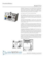
installation instructions for symcom's motorsaver® model 202-200-sp
installation instructions for symcom's motorsaver® model 202-200-sp
installation instructions for symcom's motorsaver® model 202-200-sp

Create successful ePaper yourself
Turn your PDF publications into a flip-book with our unique Google optimized e-Paper software.
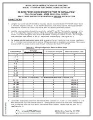
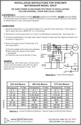
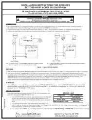
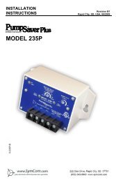
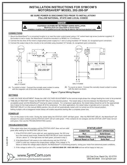
INSTALLATION INSTRUCTIONS FOR SYMCOM’SMOTORSAVER ® MODEL <strong>202</strong>-<strong>200</strong>-SPBE SURE POWER IS DISCONNECTED PRIOR TO INSTALLATION!!FOLLOW NATIONAL, STATE AND LOCAL CODES!CONNECTIONS1. Mount the MotorSaver ® in a convenient location in or near the motor control panel using a 1/4” socket head cap screw (customer supplied). Ifthe location is wet or dusty, the MotorSaver ® should be mounted in a NEMA 4 or 12 enclosure.2. Connect the two lines of the motor’s single-phase power supply to L1 and L2 using insulated 1/4” female, UL recognized quick connectors.3. Connect the output relay to the circuitry to be controlled using insulated 1/4” female, UL recognized quick connectors.(A) To control a motor: Connect the normally open contact in serieswith the magnetic coil of the motor starter as shown.SETTINGS(B) To sound an alarm: Connect the normally closed contact in serieswith the alarm as shown.Figure 1:Typical Wiring Diagram1. LINE VOLTAGE ADJUSTMENT: Rotate the LINE VOLTAGE ADJUSTMENT to the nominal single-phase line voltage feeding the motor to be protected.2. TIME DELAY RESTART: Rotate the RESTART DELAY to the desired position. The restart delay is the time between the MotorSaver ® seeingacceptable power and the MotorSaver ® closing its output contacts. For compressor applications, the restart delay should be set <strong>for</strong> the approximatetime it takes <strong>for</strong> the head pressure to bleed off of the compressor. For other applications, the restart delay is typically set to 2 seconds. If theRESTART DELAY is in the manual (MAN) position, the unit will not automatically restart until it is turned out of the manual position.Setting multiple units at staggered restart delays will enable sequential starting after a complete power loss.POWER-UPTurn on the power to the motor. During the restart delay the STATUS LIGHT will flash green. After the RESTART DELAY, the MotorSaver ® willenergize its output contacts and the STATUS LIGHT will turn solid green. If the contacts do not energize and the STATUS LIGHT does not turnsolid green, then see the TROUBLESHOOTING section.TROUBLESHOOTINGIf the output relay does not energize and the STATUS LIGHT does not turn solidgreen after waiting <strong>for</strong> the RESTART DELAY time:STATUS LIGHTCONDITION LIGHT OPERATION1. If the STATUS LIGHT turns solid red, upon applying power, the <strong>202</strong> mayRunSolid Greenbe in the manual reset mode. Rotate the RESTAR DELAY knob clockwise1/8 turn, above "2." If the light does not flash green, proceed to step 2.Restart Delay Flashing Green2. If the MotorSaver ® still seems to be malfunctioning and the STATUSLIGHT is solid red, measure the single-phase voltage. If the voltage is 7%Manual Reset or Fault Solid Redabove or below the voltage adjust setpoint, the MotorSaver ® is functioning properly, saving your motor from abnormal power conditions.3. If the voltage is within ±7%, contact SymCom at 1-800-843-8848 OR 1-605-348-5580 and we will be happy to help you.2880 North Plaza Drive, Rapid City, South Dakota 57702(800) 843-8848· (605) 348-5580· fax (605) 348-5685www.symcom.com
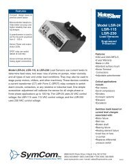
MODEL <strong>202</strong>-<strong>200</strong>-SP SPECIFICATIONSSingle-Phase Line Voltage 190-240VAC ±10%Frequency*50/60HzNominal Voltage Setpoints 190, <strong>200</strong>, 208, 220, 230, 240Low Voltage (% of setpoint)Trip 90%Reset 93%High Voltage (% of setpoint)Trip 110%Reset 107%Trip Delay TimeHigh and Low Voltage4 secondsRestart Delay TimeAfter a fault or complete power lossManual, 2-300 seconds (adjustable)Output Contact RatingSPDT480VA @ 240VAC Pilot Duty10A @ 240VAC General PurposeTransient ProtectionIEC 1000-4-5, ±4kVPower Consumption5 Watts (max.)Weight8 oz.Trip & Reset Accuracy 1%Repeatability 0.5%Input to Output Dielectric1960 Vrms (min.)Termination0.25” Male Quick ConnectHumidity95% Relative Non-CondensingOperating Temperature -40 to 70°CCE PendingUL Recognized File #E68520*50Hz will increase all delay timers by 20%DIMENSIONS FOR MODEL <strong>202</strong>-<strong>200</strong>-SPWARRANTYSeller warrants to the buyer that products furnished will be free from defects in material and workmanship, exclusive of corrosion, <strong>for</strong> a periodof five years from the date of shipment from its factory, provided said products have been installed, maintained and operated in con<strong>for</strong>mancewith any applicable <strong>sp</strong>ecifications and recommendations of the Seller. The Seller’s liability under this warranty shall be limited to thereplacement within the a<strong>for</strong>esaid time of any defective work or material limited at the Seller’s factory and shall not be liable <strong>for</strong> any labor orother repair costs made outside the Seller’s factory without the written consent of the Seller. The Seller shall be liable <strong>for</strong> no other damagesor losses. The warranty described in this paragraph shall be IN LIEU OF ANY OTHER WARRANTY EXPRESSED OR IMPLIEDINCLUDING BUT NOT LIMITED TO ANY IMPLIED WARRANTY OF MERCHANTABILITY OR FITNESS FOR A PARTICULAR PURPOSE.12/05