MODEL 235P - SymCom
MODEL 235P - SymCom
MODEL 235P - SymCom

Create successful ePaper yourself
Turn your PDF publications into a flip-book with our unique Google optimized e-Paper software.
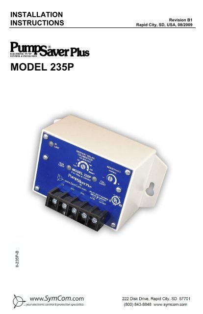
INSTALLATIONINSTRUCTIONSRevision B1Rapid City, SD, USA, 08/2009<strong>MODEL</strong> <strong>235P</strong>II_<strong>235P</strong>_B12880 North Plaza Drive, Rapid City, South Dakota 57702(800) 843-8848 · (605) 348-5580 · fax (605) 348-5685
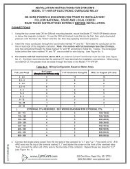
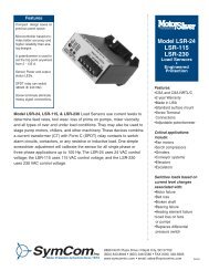
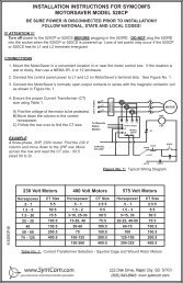
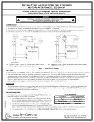
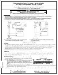
BE SURE POWER IS DISCONNECTED PRIOR TO INSTALLATION!FOLLOW NATIONAL, STATE AND LOCAL CODES.READ THESE INSTRUCTIONS ENTIRELY BEFORE INSTALLATION.The Model <strong>235P</strong> Single-phase PumpSaver ® Plus is a pump monitor designed to protect singlephasepumps from dry-well, dead-head, rapid-cycle, jammed impeller, and over/under voltageconditions. The PumpSaver ® Plus Model <strong>235P</strong> protects 5 to 15 HP, 230VAC pumps. Typicalapplications include submersible pumps, centrifugal pumps, cooling pumps, environmental pumps,residential water wells, commercial water wells, irrigation wells, and golf course or other sprinklerequipment.CONNECTIONSNOTE: Use with UL/CSA listed overload or impedance protected pumps or motors only.1. Mount the PumpSaver ® Plus Model <strong>235P</strong> in a convenient location in or near the pump controlbox. If the location is wet or dusty, a NEMA 3R, 4, or 12 enclosure should be used. ThePumpSaver ® Plus must be protected by a fuse or circuit breaker.2. Connect a current transformer (CT) to the PumpSaver’s terminals marked CT1 and CT2. (seeTable 1 for proper CT sizing).NOTE: The Model <strong>235P</strong> will not function without an external current transformer. A ULListed current transformer must be selected based on Table 1.3. Connect the PumpSaver’s terminals marked ‘L1’, ‘L2 IN’ and ‘L2 OUT’.4. Refer to the appropriate wiring diagram for your specific application.• Typical wiring diagram – Figure 1• Standard 3-wire control box – Figure 2• Deluxe control box – Figure 3NOTE: One line from the fused disconnect must pass through the current transformer.NOTE: The PumpSaver ® Plus may not detect a dead-head (blocked pipe) condition onapplications where the pump is undersized for a given motor or flow restrictors are used onhigh stage pumps or low yield wells.*** WARNING ***PROPER OPERATION REQUIRES FIELD CALIBRATION© 2009 <strong>SymCom</strong>, Inc. All Rights Reserved 2
Size Current CT5-7 ½ HP 27.5 – 42.1 50:510 HP 51 75:515 HP 75 100:5TABLE 1: Current Transformer SelectionFIGURE NO.1: Typical Wiring Diagram© 2009 <strong>SymCom</strong>, Inc. All Rights Reserved 3
© 2009 <strong>SymCom</strong>, Inc. All Rights Reserved 4
IND. CON T . EQ.OPERATIONThe PumpSaver ® Plus monitors pump load in amps and kilowatts. When the current (amps) exceedsapproximately 125% of calibrated current, or power (kW) drops below the adjustable underload trippoint, the PumpSaver ® Plus—after the trip delay—will turn off the pump. The PumpSaver ® Plus willtime through the restart delay, and then restart the pump. The calibration is stored in permanentmemory—it does not need to be recalibrated if power is lost.CALIBRATIONNOTE: The PumpSaver ® Plus should be calibratedduring normal pumping conditions.1. Turn the RESTART DELAY/ CALIBRATION knobfully counter-clockwise to the CAL. position.IRLINK2. Apply power—the pump will run for approximately10 seconds then shut off.3. Set the RESTART DELAY/ CALIBRATION knobto the desired restart delay (dry-well recoverytime)—the pump will turn on.L1 CT1 CT2PILOT DUTYRATING 480VA@240VAC784XNOTE: If the PumpSaver ® Plus immediately trips (blinking green) upon completion of thecalibration process, the current transformer may be installed incorrectly. Swap the CT1 andCT2 wires on the terminal strip, then repeat the calibration process beginning with Step #1.CALIBRATING WHILE PUMPINGThe PumpSaver ® Plus can also be calibrated while the pump is running. Turn the RESTARTDELAY/ CALIBRATION knob to CAL. while pumping. Wait for the pump to turn off (approximately10 seconds), then adjust the RESTART DELAY/ CALIBRATION knob to the desired setting.SENSITIVITYThe PumpSaver ® Plus has an adjustment knob to set the underload trip sensitivity. SettingSENSITIVITY to the middle position (straight up) is equivalent to <strong>SymCom</strong>’s standard underload triplevel. Adjust the SENSITIVITY knob to increase/decrease underload sensitivity up to approximately10% of the standard trip. It may be necessary to increase the sensitivity if the PumpSaver ® Plusdoes not trip on dry-run or dead-head or it is known that the water level in the well is very lowrelative to the pump’s capabilities.WARNING: Decreasing the SENSITIVITY may compromise the PumpSaver ® Plus’ ability todetect dry-run and/or dead-head conditions.RESET MODE / RESTART DELAYAny restart delay can be by-passed by rotating the RESTART DELAY/ CALIBRATION knob to theRESET position and back to the desired restart delay setting.NOTE: The restart delay setting can be changed at any time. The current and subsequenttrips will follow the new restart delay setting.The RESTART DELAY/ CALIBRATION knob can be placed in the RESET position for manualreset. If the PumpSaver ® Plus trips off in this mode due to a voltage or load problem, the RESTARTDELAY/ CALIBRATION knob must be rotated out of the RESET position to restart the pump.© 2009 <strong>SymCom</strong>, Inc. All Rights Reserved 5
RUN HOURS / FAULT HISTORYThe PumpSaver ® Plus records pump run hours and the last 20 faults. These values can bedisplayed by a PumpSaver ® Informer (see USING AN INFORMER later in this document). Runhours and fault history can be cleared on the PumpSaver ® Plus. Read the following instructions fullybefore performing the procedure.NOTE: Turn the SENSITIVITY knob completely to the left (counter-clockwise) or completelyto the right (clockwise) when directed. The knob must be turned in quick succession.To Reset Run Hours and Clear Fault History:1. Remove power to the PumpSaver ® Plus.2. Set the RESTART DELAY/ CALIBRATION knob to RESET and the SENSITIVITY knob to themiddle (12:00) position.3. Apply power to the PumpSaver ® Plus—the CAL. LIGHT will turn on.4. Turn the SENSITIVITY knob to the right—the CAL. LIGHT will turn off and the RUN LIGHT willturn on.5. Turn the SENSITIVITY knob to the left—both lights will turn on.6. Turn the SENSITIVITY knob to the right.7. After 10 seconds, the CAL. and RUN LIGHTS will blink twice indicating the run hours and faulthistory have successfully been cleared.RAPID CYCLINGRapid cycling is defined as more than 4 restarts in a 60-second period. The PumpSaver ® Plus iscapable of detecting a rapid-cycle condition whether a control device, such as a pressure switch, isinstalled before* or after it. Upon detecting either form of rapid cycling, the PumpSaver ® Plus willlock-out, preventing damage to the pump. To reset the PumpSaver ® Plus, remove and re-applypower.RAPID CYCLING (Line-Side / Upstream)Rapid cycling of the line side of the PumpSaver ® Plus may be caused by several naturally occurringconditions which are indistinguishable from true rapid cycling. For this reason, once tripped, thePumpSaver ® Plus will wait 30 minutes and restart. If the restart is successful (the pump runs formore than one minute), the rapid cycle counter will reset to zero. If the PumpSaver ® Plus encountersrapid cycle 4 times without a successful restart, it will lock-out and require a manual reset. To resetthe PumpSaver ® Plus, remove and re-apply power.*Protection against rapid cycling of a control device installed before the PumpSaver ® Plus isdisabled by default. Read the following instructions fully before performing the procedure to enablehis feature.NOTE: Turn the SENSITIVITY knob completely to the left (counter-clockwise) or completelyto the right (clockwise) when directed. The knob must be turned in quick succession.To Enable Line-Side/Upstream Rapid-Cycle Protection: (to disable, follow the same procedure)1. Remove power to the PumpSaver ® Plus.2. Set the RESTART DELAY/ CALIBRATION knob to RESET and the SENSITIVITY knob to themiddle (12:00) position.3. Apply power to the PumpSaver ® Plus —the CAL. LIGHT will turn on.4. Turn the SENSITIVITY knob to the right—the CAL. LIGHT will turn off, RUN LIGHT will turn on.© 2009 <strong>SymCom</strong>, Inc. All Rights Reserved 6
5. Turn the SENSITIVITY knob to the left—both lights will turn on.6. Turn the SENSITIVITY knob right—left—right—left—right.7. After 2 seconds, the CAL. and RUN LIGHTS will blink once indicating line-side rapid-cycleprotection has been enabled.RAPID CYCLING (Load-Side / Downstream)Load-side rapid cycling of the pump will immediately result in a manual lock-out. The pump will notrestart automatically. To reset the PumpSaver ® Plus, remove and re-apply power.Note: Protection against rapid cycling of a control device installed after the PumpSaver ® Plus isalways enabled. Disabling line-side detection will not disable load-side detection.USING AN INFORMERPumpSaver ® Plus products are equipped with an infrared LED that will communicate to a <strong>SymCom</strong>Informer—a handheld, battery-operated, diagnostic tool. The Informer—when directed at thePumpSaver ® Plus—will display real-time voltage, current and power; dry-well and overcurrent trippoints; calibration voltage; last 20 faults; voltage, current and power at the last fault; highest/lowestvoltage and current since calibration; the model number; and the CT size if applicable. The Informercan be used on any single-phase PumpSaver ® Plus equipped with an infrared LED transmitter.Contact <strong>SymCom</strong> for more information at 800-843-8848 or visit our website: www.symcom.com.© 2009 <strong>SymCom</strong>, Inc. All Rights Reserved 7
TROUBLESHOOTINGRUN LIGHT CAL. LIGHT PROBLEM or FUNCTION CORRECTIVE ACTIONOn SteadyOn SteadyOffOffBlinkingOffOn SteadyOn SteadyOffOffRUN:Pump is running—or ready to run—no problems in operationCAL:The PumpSaver ® Plus is in thecalibration process.CAL COMPLETE:The PumpSaver ® Plus is calibrated,the RESTART DELAY/CALIBRATION knob was left in theCAL. position. Pump is off.OFF / MANUAL RESTART:The pump is not running. Either thePumpSaver ® Plus has tripped ondry-run, dead-head, or overcurrentwhile the RESTART DELAY/CALIBRATION knob was in theRESET position or source power isnot present.DRY RUN / DEAD HEAD:The PumpSaver ® Plus has shut thepump off due to a dry-run or deadheadcondition. The unit is timingthrough the restart delay and willtry to restart.NoneNonePump will restart as soon asthe RESTART DELAY/CALIBRATION knob is rotatedout of the CAL. position.If knob is in the RESETposition, rotate out of RESET—If the CAL. light blinks, checkfor an overcurrent condition. Ifthe RUN light blinks, look for adry-run or dead-head condition.If no lights come on, checkincoming power for adequatevoltage.Check for restricted flow orinadequate supply of liquid.OffBlinkingOVERCURRENT:The PumpSaver ® Plus has shut thepump off due to an overcurrentcondition. The unit is timingthrough the restart delay and willtry to restart if line voltage is at anacceptable level.Check for low or high voltageor jammed pump impellers. Ifthese conditions do not exist,recalibrate the unit while it isdrawing higher current (ampsshould not exceed SFA).Blinkingalternatelywith theCAL. LIGHTBlinkingalternatelywith theRUN LIGHTVOLTAGE FAULT:The PumpSaver ® Plus is preventingthe pump from starting due tovoltage problems. The voltage isbeing interrogated and the unit willremain in this mode until thevoltage is at an acceptable level.If the unit remains in this statefor more than 5 seconds, checkfor high or low voltage.Blinking inunison withthe CAL.LIGHTBlinking inunison withthe RUNLIGHTRAPID CYCLE:The PumpSaver ® Plus has shutdown on rapid cycling. Power mustbe removed and reapplied to resetthe unit.Check for a broken bladder inthe pressure tank (if used), orcheck for a defective pressureor float switch.© 2009 <strong>SymCom</strong>, Inc. All Rights Reserved 8
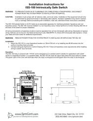
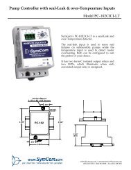
PHYSICAL DIMENSIONSFRONT VIEW2.93"(74.42)4.05" (102.87)4.50" (114.30).375"(9.53)5.26" (133.60)BOTTOM VIEW2.90"(73.66)2.17"(55.12)© 2009 <strong>SymCom</strong>, Inc. All Rights Reserved 9
SPECIFICATIONSFunctional SpecificationsAdjustments/SettingsOvercurrentUnderload (dry-well)OvervoltageUndervoltageNumber of restarts allowed in 60second period (rapid-cycling)Trip Delay TimesOvercurrentDry-wellRestart Delay TimesOver/undervoltageAll other faultsInput CharacteristicsSupply VoltageLoad RangeFrequencyOutput CharacteristicsOutput Contact Rating-SPSTGeneral CharacteristicsAmbient Operating TemperatureMaximum Input PowerWire GaugeTerminal TorqueStandards PassedElectrostatic Discharge (ESD)Surge Immunity125% of calibration pointAdjustable (70-90% of calibrated run power)265VAC190VAC45 seconds4 seconds2 secondsManual, 2-225 minutes230VAC5 to 15hp (external current transformer required)50/60 Hz (note: 50Hz will increase all delay timers by20%)720VA @ 240VAC-40° to 55°C (-40° to 131°F)5 WSolid or stranded 10 - 22AWG13 in.-lbs.IEC 61000-4-2, Level 2, 4kV contact, 6kV airIEC 61000-4-5, Level 4, 4kV line-to-line and line-togroundSafety MarksULC Listed UL508, C22.2 No. 14Dimensions2.90” H x 5.26” W x 2.93” DWeight14 oz.Mounting Methods#8 screws© 2009 <strong>SymCom</strong>, Inc. All Rights Reserved 10
For warranty information, please see Terms and Conditions atwww.symcom.comVisit us at www.symcom.com to seeour complete product listing!Need something special?Contact <strong>SymCom</strong> todayfor your custom solution!800-843-8848© 2009 <strong>SymCom</strong>, Inc. All Rights Reserved 12