connections installation instructions for symcom's model 777-hvr-sp ...
connections installation instructions for symcom's model 777-hvr-sp ...
connections installation instructions for symcom's model 777-hvr-sp ...

You also want an ePaper? Increase the reach of your titles
YUMPU automatically turns print PDFs into web optimized ePapers that Google loves.
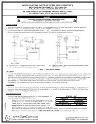
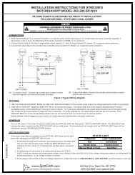
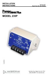
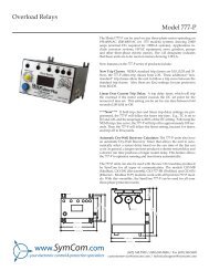
CONNECTIONSINSTALLATION INSTRUCTIONS FOR SYMCOM'SMODEL <strong>777</strong>-HVR-SP ELECTRONIC OVERLOAD RELAYBE SURE POWER IS DISCONNECTED PRIOR TO INSTALLATION!!FOLLOW NATIONAL, STATE AND LOCAL CODES!READ THESE INSTRUCTIONS ENTIRELY BEFORE INSTALLATION.1. Using the four corner tabs OR the DIN rail mounting bracket, mount the Model <strong>777</strong>-HVR-SP directly aboveor below the magnetic contactor. To use the DIN rail bracket, hook the top clip first, then apply downwardpressure until the lower clip "clicks" onto the rail, then stop applying downward pressure.2. Insert the motor conductors through the round holes marked "A" and "B." Terminate the conductors at theline or load side of the magnetic contactor. Note: For motors with full load amps less than 25 Amps,loop the conductors through the holes marked "A" and "B" according to Table No. 1 below. The rectangularholes behind the holes marked "A" and "B" are provided <strong>for</strong> wire looping. (see Figure No. 1).3.For motors with full load current above 90 A, an external Current Trans<strong>for</strong>mer must be used (see FigureNo. 2). SymCom recommends that the external CT have terminals <strong>for</strong> <strong>installation</strong> convenience. When usingan external CT, five passes must be made through the holes in the Model <strong>777</strong>-HVR-SP.Full Load AmpsTable No.1: Wiring Configuration Based on Motor Amps# of Loops( (Required on B Phaseonly)# of Conductors through B MULT to Program (CT ratio)2 - 2.59 10102.5- 38 9 93 - 3.57 8 83.5- 46 7 74 - 55 6 65 - 64 5 56 - 83 4 48 - 122 3 312- 251 2 225- 900 1 1↓ EXTERNAL CTs REQUIRED. SEE WIRING DIAGRAM FOR EXTERNAL CTs. ↓80- 1104 5 100 (100:5)110- 1604 5 150 (150:5)160- 2204 5 200 (200:5)220- 3204 5 300 (300:5)320- 4204 5 400 (400:5)400- 5204 5 500 (500:5)480- 6204 5 600 (600:5)600- 8004 5 800 (800:5)4. Connect the single-phase power from the line side of the contactor to "L1" and "L2." First insert a #12 - #18AWG wire into the top of the terminal marked "L1" and tighten the screw on the front of the overload relay.Then, connect the other end of the wire to the line side of the contactor. Repeat these two steps <strong>for</strong> "L2."(see Figure No. 1).2880 North Plaza Drive, Rapid City, SD 57702
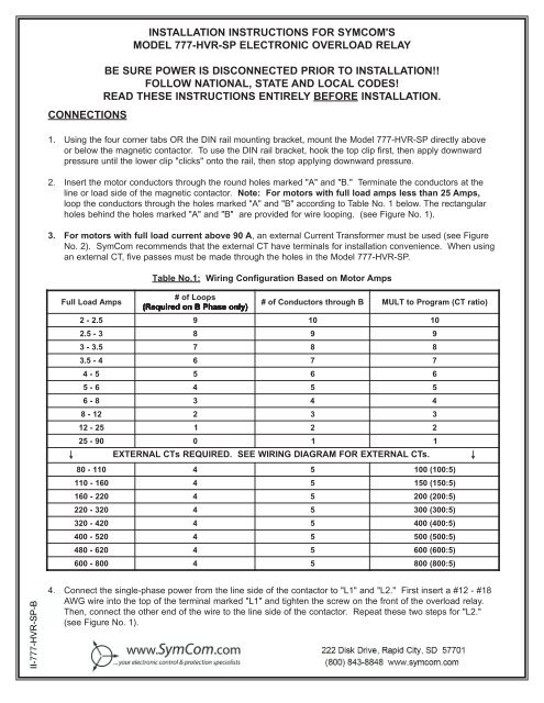
L1L2CONTACTORCOILCONTROLPOWER600 VACOR LESSA B C380-480 VAC 1Ø50/60HZPILOT DUTY RATING470 VA AT 600 VACMODEL <strong>777</strong>-HVR-SPSTARTSTOPHANDMOFFPILOTAUTOTO MOTORFigure No. 1: Typical Wiring DiagramA B C380-480 VAC 1Ø50/60HZPILOT DUTY RATING470 VA AT 600 VACCNONCMODEL <strong>777</strong>-HVR-SPFigure No. 2: Typical wiring diagram when CT is used.- 2 -
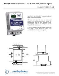
5. Connect the output relay to the circuitry to be controlled (see Figure No. 1). To control a motor, connect thenormally open contact in series with the magnetic coil of the motor starter as shown. To sound an alarm,connect the normally closed contact in series with the alarm (not shown).PROGRAMMING1. Select the feature to program by rotating the "MODESELECT" switch to the desired position. The "MULT"setting must be programmed be<strong>for</strong>e any of the currentsettings to ensure proper di<strong>sp</strong>lay of actual currentsetpoints. There<strong>for</strong>e, SymCom recommend<strong>sp</strong>rogramming the "LV" setting first, then move clockwisethrough the postions to complete the process.MODEL <strong>777</strong>-HVR-SPCNONC2. Push and hold the “RESET / PROGRAM” button.3. Rotate the “DISPLAY / PROGRAM” adjustment tothe desired setting of the feature as shown in theLED di<strong>sp</strong>lay.4. Release the “RESET/PROGRAM” button. The Model <strong>777</strong>-HVR-SP is programmed when the button isreleased.5. Continue steps 1-4 until all features are programmed.SUGGESTED SETTINGS (Consult the Motor Manufacturer <strong>for</strong> their recommendations.)[Don't <strong>for</strong>get to read the programming examples on page 5.]LV/HV- The recommended settings <strong>for</strong> "LV" (low voltage) and "HV" (high voltage) depend on many factorssuch as motor usage, motor size, environmental factors and tolerance of the motor. The motor manufacturershould be consulted <strong>for</strong> "HV" and "LV" settings. However, the NEMA MG1 standard recommendsthat "LV" and "HV" be set to no more than ±10% of the motor's nameplate voltage. The settingcan be determined by multiplying the motor's nameplate voltage by the recommended percentover and under voltage. (eg., The motor nameplate voltage is 460 V, set "LV" to 0.9x460=414, set"HV" to 1.10x460=506) "LV" can not be set higher than "HV", so "HV" may have to be adjustedhigher be<strong>for</strong>e the proper "LV" setting can be programmed.MULT- "MULT" is the multiplication factor <strong>for</strong> determining true current settings and represents the number ofconductors passing through the main current windows marked "A" and "B," or current trans<strong>for</strong>merratio of external CTs. The appropriate number can be determined from Table No. 1 on page 1."MULT" must be correctly programmed in order to accurately program the current settings.OC-UC-TC-Represents the motor's maximum service factor amperage. The "OC" (overcurrent) settingdepends on many factors such as motor usage, motor size, environmental factors and tolerance ofthe motor. The motor manufacturer should be consulted <strong>for</strong> "OC" settings. However, "OC" is typicallybetween 110% and 125% of full load amperage (FLA).The "UC" (under current) setting is typically set to 80% of full load amperage (FLA). The overloadrelay with a "UC" setting of 80% of FLA will typically detect a loss of load <strong>for</strong> many pumps andmotors such as a dry well condition <strong>for</strong> submersible pumps. The "UC" setting may be set to 0.00 todisable under current (loss of load) protection."TC" designates the trip class <strong>for</strong> overload protection. The trip class defines the trip delay when anoverload is detected (see Table No. 2). Trip class is determined by the type of motor and application.Your motor manufacturer should be consulted <strong>for</strong> the proper setting. The following table showsthe trip class and a general description of the applications.- 3 -
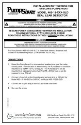
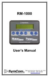
RD1-Trip Class510"RD1" is the rapid cycle timer. It will engage when the motor is first powered-up or after the motorcontrols shut down the motor. An "RD1" setting of 20-30 seconds will generally protect the motorfrom rapid, successive power outages or short cycling caused by the motor controls. A setting of 0seconds will allow the motor to start immediately after power-up or after a normal shutdown.Application DescriptionSmall fractional horsepower motors where acceleration times are almost instantaneous orwhere extremely quick trip times are required.(Fast Trip) Hermetic refrigerant motors, compressors, submersible pumps and generalpurpose motors that reach rated <strong>sp</strong>eed in less than 4 seconds.15Certain <strong>sp</strong>ecialized applications.20(Standard Trip) Most NEMA-rated general purpose motors will be protected by this setting.30(Slow Trip) Motors with long acceleration times (>10 seconds) or high inertia loads.J PrefixLInProgramming any of the trip classes with the J Prefix will enable jam protection. Thisadditional protection is enabled 1 minute after the motor starts and will enable a 2-second triptime <strong>for</strong> motors exceeding 400% of OC setting, regardless of trip class.Programming the trip class to LIn disables the normal trip classes shown above and enablesa linear trip delay on overcurrent. The linear trip delay is set in program position OPT1.Table No. 2: Trip Class Descriptions10000Overload Trip ClassesTrip Time (Seconds)100010010Class 30Class 20Class 15Class 10Class 510 100 200 300 400 500 600 700 800 900 1000% of OC SettingFIGURE #3: Overload Trip Classes- 4 -
RD2-RD3-#RU-"RD2" is the restart delay after the overload relay trips on overload. This delay allows the motor tocool down after experiencing an overcurrent. It is also known as a motor cool down timer. Yourmotor manufacturer should be contacted to determine this setting. Under normal circumstances, asetting of 5-10 minutes will give the motor enough time to cool down between faults."RD3" is the restart delay after an undercurrent. It is also known as a dry well recovery timer and isusually used in submersible pumping applications. The setting of "RD3" depends on the recoverytime of the water well and varies widely from application to application."#RU" is the number of successive restart attempts allowed after an undercurrent fault be<strong>for</strong>e theoverload relay requires manual reset. A setting of "0" is manual reset and a setting of "A" is continuouslyautomatic reset.ADDR- "ADDR" is the address setting <strong>for</strong> RS485 communications. Available settings are from A01 -A99.You may ignore this setting if RS485 communications are not used.#RO-"#RO" is the number of successive restart attempts allowed after an overcurrent fault. The followingsettings are available: 0, 1, 2, 3, 4 and A. A setting of "0" is manual reset and a setting of "A" iscontinuously automatic.UCTD- "UCTD" is the undercurrent trip delay timer. This setting represents the maximum time that theModel <strong>777</strong>-HVR-SP will tolerate an under current condition. Typically, UCTD is set to 2 - 4 seconds.OPT1- Linear overcurrent trip delay (2-60 seconds). This programming position is used only if the TC positionis set to LIn. This setting will determine the period of time that will expire be<strong>for</strong>e tripping onovercurrent, after the amperage exceeds the OC setting. (See Programming Example #2).OPT2- RD2 & RD3 time units programming. This position sets the time units used by the RD2 and RD3timers. (e.g., RD2 = 10, RD3 = 20, OPT2 = 2 from the table below; RD2 = 10 seconds and RD3 =20 minutes.SETTINGRD2RD30 Minutes1 Minutes2 Seconds3 SecondsMinutesSecondsMinutesSecondsPROGRAMMING EXAMPLES#1 Motor To Be Protected: 1Ø, 460 Volt, 20 Hp raw material transfer auger. This auger moves material from alarge bulk delivery pit to the production area main storage hopper. The motor has afull load amperage rating of 50 Amps and a maximum service factor of 57 Amps.Use the following calculations and reasoning to determine the appropriate settings<strong>for</strong> this application.LV- 460 x 0.90 = 414HV- 460 x 1.10 = 506MULT - From Table No. 1; MULT = 1OC- 57- 5 -
UC-TC-Since the motor current will unload at least 20% if a shaft shear pin breaks or the auger runs out ofmaterial, UC = 50A x 0.80 = 40Because the motor is a general purpose motor and the motor should be protected from beingjammed by a <strong>for</strong>eign object, TC = J20UCTD- 5-10 secondsRD1- To protect the motor from rapid successive power outages, RD1 = 20RD2-RD3-#RU-#RO-ADDR- N/A.OPT1- N/A.OPT2- N/A.N/A, see #RO setting.N/A, see #RU setting.Setting #RU to 0 will require a manual reset after undercurrent. There<strong>for</strong>e, RD3 has no affect in thisapplication. This setting will allow the auger to be started, and left unattended, and will run until thedelivery pit is empty. Pressing a remote reset button will start the auger <strong>for</strong> the next load.Setting #RO to 0 will require a manual reset after an overcurrent. There<strong>for</strong>e, RD2 has no affect.#2 - Application: A 3Ø, 460 Volt, 50 Hp motor with 65 FLA and 75 SFA is used to shred plastic <strong>for</strong>recycling. The shredder is fed by a conveyor. This example shows how the Model <strong>777</strong>-HVR-SP isused to control the conveyor to prevent the 50 Hp shredder motor from being overloaded by excessmaterial being fed by the conveyor.LV- 0.90 x 460 = 414HV- 1.10 x 460 = 506MULT - From Table No. 1, MULT = 1OC-UC-TC-UCTD- 5-1070 Amps, keeps motor from reaching service factor Amps during normal operation.The conveyor should be stopped only on severe undercurrent conditions; i.e., broken shear pin onshredder. UC = 65 x 0.50 = 32Because the shredder can become quickly overloaded by excessive material feed, TC = LIn.RD1- Rapid cycling is not a concern in this application, RD1 = 0.RD2-RD3-The motor will quickly regain its <strong>sp</strong>eed after the conveyor stops feeding material, RD2 = 5. This willallow the conveyor to start feeding material 5 seconds after tripping on overcurrent.N/A, see #RU.#RU- Because an undercurrent would indicate a serious problem, #RU = 0.#RO- This sytem will potentially overload many times, #RO = A.ADDR- N/A.OPT1- Linear overcurrent trip delay = 2 seconds. This will stop the conveyor 2 seconds after it starts tooverload and exceeds 70 amps.OPT2- RD2 must be in seconds. There<strong>for</strong>e, a setting of 2 in OPT2 should be used in this application.- 6 -
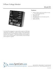
COMMUNICATIONS PORT / REMOTE RESETThe Model <strong>777</strong>-HVR-SP comes standard with a 9-pin Sub D connector <strong>for</strong> remote communications. The Model<strong>777</strong>-HVR-SP supports RS-485 communication standard. This standard allows up to 99 Model <strong>777</strong>-HVR-SPsto be controlled and monitored from a single remote personal computer. NOTE: An RS-485 module andsoftware is required to operate the communications bus. (Refer to RS-485 Installation Instructions <strong>for</strong> morein<strong>for</strong>mation on this subject.)The communications port also provides <strong>connections</strong> <strong>for</strong> remote reset as shown below.5 4 3 2 16 7 8 9Normally Open Push ButtonMULTI-FUNCTION SYSTEM DISPLAYThe output di<strong>sp</strong>lay can show various system operating parameters: L1-L2 Voltage, L2 Current (B).When the "MODE SELECT" switch is in the "RUN" position, the LED will di<strong>sp</strong>lay one of the above operatingparameters. To select or change the di<strong>sp</strong>layed parameter, turn the "DISPLAY / PROGRAM" adjustment tothe desired position as shown on its label.The multifunction di<strong>sp</strong>lay also announces system faults such as low voltage and high voltage. Any time the"MODE SELECT" switch is in the "RUN" position, the "RESET/PROGRAM" button may be pushed to viewthe last fault which occurred. The table below shows the possible messages.Di<strong>sp</strong>layed MessageocucH ILoTripped on OvercurrentTripped on UndercurrentTripped on High VoltageTripped on Low VoltageMeaningo FFA stop command was issued from a remote source.TROUBLESHOOTINGPROBLEMThe unit will not start. Di<strong>sp</strong>layalternates "HI" or "Lo" with the"DISPLAY / PROGRAM" switchparameter value.Di<strong>sp</strong>layalternates "oc" with "RUN."Di<strong>sp</strong>layalternates "uc" with "RUN."Di<strong>sp</strong>layis showing a solid "oc."Di<strong>sp</strong>layis showing a solid "uc."SOLUTIONThe incoming voltage is not within the limits programmed in the "HV" and "LV"settings. Adjust the "DISPLAY / PROGRAM" switch to read the incoming linevoltage value. Correct the incoming power problem and check programmed limitsto verify they are correct.The overloadrestarting.relay has tripped on overcurrent and is timing down "RD2" be<strong>for</strong>eThe overload relay has tripped on undercurrent and is timing down "RD3" be<strong>for</strong>erestarting. If undercurrent is not a normal condition <strong>for</strong> this <strong>installation</strong>, check <strong>for</strong>broken shafts, broken belts, etc.The unit has tripped on overcurrent and manual reset is required because of theprogrammed setting in "#RO." Check the system <strong>for</strong> problems that would producethe overload fault like a jam.The unit has tripped on undercurrent and a manual reset is required because of theprogrammed setting in "#RU." Check the system <strong>for</strong> problems that would producean underload condition like a broken belt or shear pin.If you need further assistance, call us at 1-800-843-8848 . . . we'd be happy to help!!!!- 7 -
OPERATIONOnce the overload relay has been programmed, turn the "MODE SELECT" switch to the "RUN" position.The LED di<strong>sp</strong>lay will flash "RUN" alternatively with a number representing the parameter indicated by the"DISPLAY / PROGRAM" adjustment. After the period of time programmed into RD1, the output contacts willclose and the value of the parameter indicated by the "DISPLAY / PROGRAM" adjustment will appear on theLED di<strong>sp</strong>lay.If a message other than those indicated above is shown on the LED di<strong>sp</strong>lay, see the TROUBLESHOOTINGsection on page 7 to diagnose the problem.SPECIFICATIONSOVERLOAD RELAYElectricalInput Voltage380 - 480 VAC, 1ØFrequency50-60 HzMotor Full Load Amp Range - 77C2-25 Amps, 3Ø(Loops Required)26-90 Amps, 3Ø(Direct)91-800 Amps, 3Ø(External CTs)Motor Full Load Amp Range - 77LR1.0 Amps - 2.5 Amps (Loops Required)2.0 Amps - 9.0 Amps (Direct)Short Circuit10kAPower Consumption10W (Maximum)Output Contact Rating SPDT (Form C)Pilot duty rating: 470 VA @ 600 VACExpected LifeMechanical1 x 10 6 operationsElectrical1 x 10 5 operations at rated loadAccuracy at 25° C (77° F)Voltage ±1%Current±3% (Direct, No External CTs)Timing5% ± 1 secondRepeatabilityVoltage± 0.5% of nominal voltageCurrent± 1% (Direct, No External CTs)Safety MarksULUL508CE IEC 60947-1, IEC 60947-5-1Standards PassedElectrostatic Discharge (ESD)IEC 1000-4-2, Level 3, 6kV contact, 8kV airRadio Frequency Immunity (RFI) IEC 1000-4-6Level 3, 10V/mFast Transient Burst IEC 1000-4-4Level 3, 3.5kV input power, 1kV control busSurgeIEC 1000-4-5Level 2, 2kV line-to-line, 4kV line-to-groundANSI/IEEEC62.41 Surge and Ring Wave Compliance to a level of 6kV line-to-lineHi-potential TestMeets UL508 (2 x rated V +1000V <strong>for</strong> 1 minute)VibrationIEC 68-2-6, 10-55Hz, 1mm peak-to-peak, 2 hours, 3 axisShockIEC 68-2-27, 30g, 3 axis, 11ms duration, half-sine pulseMechanicalDimensions3.0"H x 5.1 " D x 3.6"WTerminal Torque7 inch•lbEnclosure MaterialpolycarbonateWeight1.2 lbsMaximum Conductor Size Through <strong>777</strong>0.65" with insulationEnvironmentalTemperature RangeAmbient Operating: -20° - 70° C (-40° - 158°F)Ambient Storage: -40° - 80° C (-40° - 176°F)Pollution Degree 3Class of Protection IP20, NEMA 1Relative Humidity 10-95%, non-condensing per IEC 68-2-3Programmable Operating PointsRangeLV- Low Voltage Threshold340V - HV SettingHV- High Voltage ThresholdLV Setting - 528VMULT- # of Loops or CT Ratio (XXX:5) 77C, 1-10 Loops or 100-800 Ratio 77C-LR 1 or 2OC- Over Current Threshold(20-100A) ÷ MULT or 80-120% of CT PrimaryUC- Under Current Threshold(0, 10-98A) ÷ MULT or 40-100% of CT PrimaryCUB- Current Unbalance Threshold 2 - 25% or 999%TC- Over Current Trip Class *5, J5, 10, J10, 15, J15, 20, J20, 30, J30, or lin (linear)RD1- Rapid Cycle Timer0, 2 - 500 SecondsRD2- Restart Delay After All Faults Except Under Current 2 - 500 Minutes/Seconds(motor cool down timer)**RD3- Restart Delay After Under Current2 - 500 Minutes/Seconds(dry well recovery timer)#RU- Number of Restarts After Under Current0, 1, 2, 3, 4, A(Automatic)ADDR- RS485 AddressA01- A99#RO-Number of Restarts After Over Current ***0, 1, 2, 3, 4, A(Automatic)UCTD- Under Current Trip Delay2 - 60 SecondsNOTES: SymCom's Overload Relay can be preprogrammed prior to <strong>installation</strong> by applying 120 VAC between the L1and L2 terminals.* If J Prefix is di<strong>sp</strong>layed in trip class setting, jam protection is enabled. If programmed to LIn position,overcurrent trip delays are fixed linear time delays set in OPT1 position.** RD2 & RD3 can be changed from minutes to seconds under program position OPT2.- 8 -