
Create successful ePaper yourself
Turn your PDF publications into a flip-book with our unique Google optimized e-Paper software.
Table of ContentsMotor ProtectionMotor Protection Devices . . . . . . . . . . . . . . . . . . . . . . . . . . . . . . . 2<strong>777</strong>-xxx, <strong>777</strong>-P-xxx, 77C-xxxCommunication Modules . . . . . . . . . . . . . . . . . . . . . . . . . . . . . . . . 7RS485MS-2W, COM-DN-P, COM-4-20mA, CIO-DN-P, CIO-<strong>777</strong>-PRRemote Monitoring Devices. . . . . . . . . . . . . . . . . . . . . . . . . . . . . . 9RM-1000, RM-2000Solutions Software . . . . . . . . . . . . . . . . . . . . . . . . . . . . . . . . . . . . . 11Solutions-M, Solutions-DVoltage Monitors3-Phase Voltage Monitors. . . . . . . . . . . . . . . . . . . . . . . . . . . . . . . . 1280, 102A, 201A, 201A-AU, 202, 250A, 350, 355, 455, Informer-MS, 460, 601Single-Phase Voltage Monitors . . . . . . . . . . . . . . . . . . . . . . . . . . . . 2750R, 201-xxx-SP, 202-200-SP, 460-xxx-SPCurrent Monitors3-Phase Current Monitors . . . . . . . . . . . . . . . . . . . . . . . . . . . . . . . 32520CS, 520CPSingle-Phase Current Monitors . . . . . . . . . . . . . . . . . . . . . . . . . . . 35CP-5Alternating Relays . . . . . . . . . . . . . . . . . . . . . . . . . . . . . . . . . . . . . . . . 37ALT-xxx-S, ALT-xxx-X, 50R-400-ALTIntrinsically-Safe Relays . . . . . . . . . . . . . . . . . . . . . . . . . . . . . . . . . . . . 39ISS-100, ISS-101, ISS-102, ISS-105Pump Controllers . . . . . . . . . . . . . . . . . . . . . . . . . . . . . . . . . . . . . . . . . 43PC-102, PC-105, 201-100-SLD, 460-15-100-SLD, 460-15-100-LLSPumpSavers3-Phase PumpSavers. . . . . . . . . . . . . . . . . . . . . . . . . . . . . . . . . . . . 49<strong>777</strong>-<strong>KW</strong>/<strong>HP</strong>, <strong>777</strong>-TS, <strong>777</strong>-AccuPowerSingle-Phase PumpSavers . . . . . . . . . . . . . . . . . . . . . . . . . . . . . . . . 5477C-<strong>KW</strong>/<strong>HP</strong>, 111/112/232-Insider, 231-Insider-P, 111, 233-P, 235, InformerLoad Sensors. . . . . . . . . . . . . . . . . . . . . . . . . . . . . . . . . . . . . . . . . . . . . 61LSR-0, LSR-24, LSR-115, LSR-230, LS-524, LSRU, LSRX, LSRX-CAuxiliary Products . . . . . . . . . . . . . . . . . . . . . . . . . . . . . . . . . . . . . . . . 66T-10, Current Transformers, Enclosures, Phase 3, Megger, Kits, Octal SocketsProduct Enclosure Dimensions. . . . . . . . . . . . . . . . . . . . . . . . . . . . . . . 70Appendix A:Typical Wiring Diagrams. . . . . . . . . . . . . . . . . . . . . . . . . . 76Terms and Conditions. . . . . . . . . . . . . . . . . . . . . . . . . . . . . . . . . . . . . . IBCwww.symcom.com • tel: 605-348-5580 800-843-8848 • fax: 605-348-56851
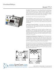
Motor Protection DevicesMotor Protection Relays in the <strong>Model</strong> <strong>777</strong> product family are more than simple overload relays. They are complete motor,pump and system protection devices. These protection relays combine voltage and current monitoring to providerobust motor management.The <strong>Model</strong> <strong>777</strong>overload relay can be used to protect any 3-phase motor drawing 2-800amps (external CTs are required above 90A). It combines overload, underload,and voltage and power monitoring functions in one package and has a3-digit display for viewing voltage, current, and last fault information to simplifydiagnostics. <strong>Model</strong> <strong>777</strong> products are UL listed, CSA recognized and CEapproved.Specialized <strong>Model</strong> <strong>777</strong> units are available to provide linear trip capability,handle medium voltage applications, provide low power trip functions forspecial pumping applications and more. See page 4 for descriptions ofavailable specialized <strong>Model</strong> <strong>777</strong>s.Adding an optional Modbus, DeviceNet or Profibus communications moduleenables communications.See Appendix A, Figures 1 & 2 for typical wiring diagrams.For available models see Product Selection Matrix on page 3.Features• Power factor measurement• Power measurement• Run-hour meter• Programmable automatic, semiautomaticor manual restart control• 3 separate restart timers for rapid-cycle protection,motor cool down and dry-well recovery• Remote pushbutton reset option• Built-in 3-digit display for setup and diagnostics• Last fault indication on display• Last 4 faults available on network or remote displays• Optional remote displays (RM-1000 and RM-2000)• Communication capabilities• Adjustable underload trip delayProtects 3-Phase motors from:• High and low voltage• Voltage unbalance• Loss of any phase (single-phasing)• Phase-reversal• Undercurrent• Overcurrent• Single-phase current• Current unbalance• Ground fault• Contact failure• Rapid cycling2 www.symcom.com • tel: 605-348-5580 800-843-8848 • fax: 605-348-5685
<strong>777</strong> Product LineProduct Selection MatrixMODEL<strong>777</strong>-P<strong>777</strong>-P1<strong>777</strong><strong>777</strong>-LR-P<strong>777</strong>-LR<strong>777</strong>-LR-FT<strong>777</strong>-HVR-LR<strong>777</strong>-LR-<strong>KW</strong>/<strong>HP</strong><strong>777</strong>-LR-TS<strong>777</strong>-HVR<strong>777</strong>-HVR-<strong>KW</strong>/<strong>HP</strong><strong>777</strong>-HVR-NP<strong>777</strong>-MV<strong>777</strong>-MV-FT<strong>777</strong>-575<strong>777</strong>-575-P<strong>777</strong>-575-P1<strong>777</strong>-575-FT<strong>777</strong>-575-HVR<strong>777</strong>-575-<strong>KW</strong>/<strong>HP</strong><strong>777</strong>-575-LR<strong>777</strong>-575-TS<strong>777</strong>-AccuPower<strong>777</strong>-FT<strong>777</strong>-<strong>KW</strong>/<strong>HP</strong><strong>777</strong>-<strong>KW</strong>/<strong>HP</strong>-P<strong>777</strong>-PH<strong>777</strong>-TS<strong>777</strong>VA-02High VoltageLow VoltagePhase LossPhase ReversalVoltage UnbalanceContact FailureLow Current TripLow Power TripThermal OvercurrentSubtrol High Temp. Trip*Linear Overcurrent TripHigh Power Trip**Current UnbalanceClass II Ground Fault12.5-600A with CTs1-9 Amps2-800 Amps190-480 VAC100-240 VAC380-480 VAC480-600 VAC277V Relay600V Relay77C77C-LR77C-LR-<strong>KW</strong>/<strong>HP</strong><strong>777</strong>-HVR-SP77C-<strong>KW</strong>/<strong>HP</strong>* Subtrol is a registered trademark of Franklin Electric Co., Inc.** Network programmable ONLYAccessories• Communications modules (see pgs. 7-8)• RM-1000/RM-2000 (remote displays) (see ps. 9-10)• Solutions software (see pg. 11)• Manual remote reset kit (see pg. 69)www.symcom.com • tel: 605-348-5580 800-843-8848 • fax: 605-348-56853
<strong>777</strong> Product Line-P Has a Hp setpoint network programmable,TC setpoints from 2-30 (j) and linear trip from 2-60 seconds.-P1 Has high power and low power alarm setpoints available via Solutions Software.-LR (Low Range) The <strong>777</strong>-LR is specifically designed for use with 1-9 full load amp motors to ease installation.-HVR The <strong>777</strong>-HVR is required when a CPT (control power transformer) is not used on a 480V system. It has a 380-480V range,a relay rated at 480VA @ 600VAC pilot duty, and are commonly used in pumping applications to save the cost and extra wiringassociated with a CPT.-MV The <strong>777</strong>-MV is specifically designed for medium voltage applications where both PTs (potential transformers) andCTs (current transformers), are used. It has a 115-230V nominal voltage range, and built-in multipliers for 25:5, 50:5, 100:5, …CTs.The voltage unbalance, single-phase and reverse-phase protection can be disabled to accommodate applications where only one PTis used.-575 The <strong>777</strong>-575 has a nominal 480-600VAC range and 240V relay. They are commonly used in Canada and the Northeast USwhere 575V utility power services are common.-<strong>KW</strong>/<strong>HP</strong> The <strong>777</strong>-<strong>KW</strong>/<strong>HP</strong> has the underload trip based on power.The underpower trip feature is desirable anytime the currentvs. load characteristic is non-linear or has little change.-FT The <strong>777</strong>-FT is intended for applications where a fast linear trip is required. It has an overcurrent trip delay that can be set toless than 500 ms, to be used in applications where very short trip delays are needed to prevent chain drives and other drivelinkages from breaking in an overload or jam situation. Often times these are referred to as shock relays. Some applications includesewage clarifiers, mixers, augers and conveyors. The trip delay can be set to as long as 70 seconds, so the <strong>777</strong>-FT can also be usedin certain applications when a slower than normal trip is desired, such as motor test panels in a rewind shop.-PH The <strong>777</strong>-PH is specifically designed for use with static and rotary single to 3-phase converters.Voltage unbalance protectionis disabled and the high and low voltage trip features apply only to the utility supplied power. This allows the <strong>777</strong> to ignore theseverely unbalanced voltages that are inherent to unloaded phase converters.-TS The <strong>777</strong>-TS is specifically designed for use with a Subtrol ® -equipped Franklin submersible motor to detect high motor temperatures.-NP The <strong>777</strong>-HVR-NP uses no parity when communicating on a Modbus network.-VA-02 The <strong>777</strong>VA-02 has RD1 setpoints of 2-500 minutes and UCTD setpoints of 2-60 minutes. (Part no. was <strong>777</strong>-RD1M-UCTDM).-SP The <strong>777</strong>-HVR-SP is specifically designed for single-phase, 480VAC applications . It has a high voltage relay rated at 480VA @600VAC pilot duty to handle systems with no control power transformer.4 www.symcom.com • tel: 605-348-5580 800-843-8848 • fax: 605-348-5685
<strong>777</strong> Product LineSpecificationsElectricalNominal Input Voltage<strong>777</strong>, <strong>777</strong>-P, <strong>777</strong>-P1. <strong>777</strong>-LR, <strong>777</strong>-LR-P • • • • • • • 190-480VAC<strong>777</strong>-TS, <strong>777</strong>-LR-TS • • • • • • • • • • • • • • • • • • 190-480VAC<strong>777</strong>-FT, <strong>777</strong>-LR-FT • • • • • • • • • • • • • • • • • • • 190-480VAC<strong>777</strong>-PH, <strong>777</strong>VA-02 • • • • • • • • • • • • • • • • • • 190-480VAC<strong>777</strong>-MV, <strong>777</strong>-MV-FT • • • • • • • • • • • • • • • • • • 110-240VAC<strong>777</strong>-HVR, <strong>777</strong>-HVR-LR • • • • • • • • • • • • • • • • 380-480VAC<strong>777</strong>-HVR-NP • • • • • • • • • • • • • • • • • • • • • • 380-480VAC<strong>777</strong>-575, <strong>777</strong>-575-P, <strong>777</strong>-575-P1 • • • • • • • • • • 480-600VAC<strong>777</strong>-575-TS, <strong>777</strong>-575-FT • • • • • • • • • • • • • • • 480-600VAC<strong>777</strong>-575-HVR, <strong>777</strong>-575-LR • • • • • • • • • • • • • 480-600VACFrequency • • • • • • • • • • • • • • • • • • • • • • • • • • • 50/60HzMotor Full Load Amp Range<strong>777</strong>-LR, <strong>777</strong>-HVR-LR, <strong>777</strong>-LR-TS• • • • • • • • • • • 1-9A<strong>777</strong>-LR-P, <strong>777</strong>-575-LR • • • • • • • • • • • • • • • • • 1-9A<strong>777</strong>-MV, <strong>777</strong>-MV-FT • • • • • • • • • • • • • • • • • 12.5-600A with CTs<strong>777</strong>, <strong>777</strong>-P, <strong>777</strong>-P1, <strong>777</strong>-575-P, <strong>777</strong>-575-P1• • • • 2-800A (external CTs required above 90A)<strong>777</strong>-HVR, <strong>777</strong>-575, <strong>777</strong>-575-HVR • • • • • • • • • 2-800A (external CTs required above 90A)<strong>777</strong>-TS, <strong>777</strong>-575-TS. <strong>777</strong>VA-02 • • • • • • • • • • • 2-800A (external CTs required above 90A)<strong>777</strong>-FT, <strong>777</strong>-LR-FT, <strong>777</strong>-575-FT • • • • • • • • • • • 2-800A (external CTs required above 90A)<strong>777</strong>-PH, <strong>777</strong>-HVR-NP • • • • • • • • • • • • • • • • • 2-800A (external CTs required above 90A)TC- Overcurrent Trip Class • • • • • • • • • • • • • • • • • 5, 10, 15, 20, 30 (J prefix enables jam protection feature)TC- Overcurrent Trip Class (-P units)• • • • • • • • • • • • 02-30, J02-J30, L00-L60 or OffShort Circuit Rating • • • • • • • • • • • • • • • • • • • • • 100kAPower Consumption • • • • • • • • • • • • • • • • • • • • • 10 Watts (max.)Output Contact Rating SPDT (Form C) • • • • • • • • • • Pilot duty rating: 480VA @ 240VAC, General purpose: 10A @ 240VAC• • • • • • • • • • • • • • • • • • • • • • • • • • • • 480VA @ 600VAC for HVR <strong>Model</strong>sAccuracyVoltage • • • • • • • • • • • • • • • • • • • • • • • • • • ±1%Current• • • • • • • • • • • • • • • • • • • • • • • • • • ±3%(
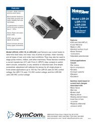
<strong>Model</strong> 77CThe <strong>Model</strong> 77Cis a fully-programmable electronic overload relay designed to monitor single-phasesystems. It can be used as a stand-alone product or the communication portcan be used to form a network to monitor the motors from a PC, or other controlsystem. Applications include conveyor systems, HVAC equipment, pumps, saws,grinders, and other single-phase electric motors.Available <strong>Model</strong>s:77C77C-LR<strong>777</strong>-HVR-SP*The <strong>Model</strong> 77C includes a built-in current transformer (CT) which will handleapplications from 2-90A. An external current transformer can be implemented tohandle applications up to 800A.The following 14 parameters can be viewed fromthe 3-digit alphanumeric display or from a network computer: low voltage trippoint, high voltage trip point, CT size/loops setting, overcurrent trip point,undercurrent trip point, trip class (5, 10, 25, 20, 30, or linear), rapid-cycle timer(RD1), overload restart delay (RD2), underload restart delay (RD3), number ofstarts after an overload (manual or automatic), RS-485 address, number ofrestarts after an underload fault, underload trip delay, and linear overcurrent tripdelay. Both voltage and line current can also be viewed while the motor is running.The <strong>Model</strong> 77C can be used with an optional RS-485 module (pn RS485MS-2W)allowing up to 99 <strong>Model</strong> 77C, <strong>Model</strong> <strong>777</strong>, <strong>Model</strong> 601,or RM-2000 units to belinked together using Modbus. From the computer, an operator can control themotor, view the operating parameters, and log information. Software and RS-485module sold separately.See Appendix A, Figures 30 & 31 for typical wiring diagrams.SpecificationsControl Power77C, 77C-LR • • • • • • • • • • • • • • • • • • • • 100-240VAC, single-phase<strong>777</strong>-HVR-SP• • • • • • • • • • • • • • • • • • • 380-480VAC, single-phaseFrequency • • • • • • • • • • • • • • • • • • • 50*/60HzMotor Full Load Amp Range • • • • • • • • 2-800A (standard)• • • • • • • • • • • • • • • • • • • • • • • • • • • 1-9A (LR option)TC- Overcurrent Trip Class• • • • • • • • • 5, 10, 15, 20, 30 (J prefix• • • • • • • • • • • • • • • • • • • • • • • • • • • enables jam protection feature)Short Circuit Withstand Rating • • • 100kA per UL and CSAPower Consumption • • • • • • • • • • • 10 Watts (max.)Output Contact Rating SPDT (Form C)77C, 77C-LR • • • • • • • • • • • • • • • • • • Pilot duty: 480VA @ 240VAC<strong>777</strong>-HVR-SP• • • • • • • • • • • • • • • • • • • Pilot duty: 470VA @ 600VACGeneral purpose: 10A @ 240VACAccuracy at 25º C (77º F)Voltage • • • • • • • • • • • • • • • • • • • • • • ±1%Current • • • • • • • • • • • • • • • • • • • • • ±3%(direct - no external CTs)Timing • • • • • • • • • • • • • • • • • • • • • • 5% ±1 secondRepeatabilityVoltage • • • • • • • • • • • • • • • • • • • • • • ±0.5% of nominal voltageCurrent • • • • • • • • • • • • • • • • • • • • • ±1% (
Communication ModulesThe RS485MS-2W Communication Moduleis required to enable the Modbus communications function on <strong>Model</strong> 77X-type products.This module is required when the RM-1000, RM-2000 or other Modbus capable device isused with 77X-type products.Specifications• Optical isolation from line potentials• Powered by the 77X product• RS-485 compliant bus drive capability• Remote reset input connection• Power connection for the <strong>Model</strong> RM-1000Available <strong>Model</strong>s:RS485MS-2WCOM-DN-PCOM 4-20The COM-DN-P DeviceNet Communication Moduleallows <strong>Model</strong> <strong>777</strong>-P type products to be used on a DeviceNet ® network.Specifications• Group 2 slave only• Overload device type• Polled messaging, configurable to 50 bytes• Supports Group 4 Automatic Node Recovery messaging• DeviceNet compatibleThe 4-20mA Output Moduleis intended for use with the <strong>Model</strong> <strong>777</strong>-AccuPower output power monitor.The module willsend a 4-20mA signal proportional to the output power. It can also be used to send theinput power by setting the efficiency setting on the <strong>777</strong>-AccuPower monitor to one.This module allows communication to a PLC with an analog input and no Modbus input.Specifications• Self powered• Scalable 4-20mA output proportional to Hp or kW• Signal can be used for displays, controllers, or PLCsCommunication Adapters• RS485-RS232 conv. with cable & plug• RS485-USB conv. with cable & plug/RS232:USB conv.actual unit may vary from picturewww.symcom.com • tel: 605-348-5580 800-843-8848 • fax: 605-348-56857
Communication ModulesAvailable <strong>Model</strong>s:CIO-DN-PCIO-120-DN-PDeviceNet IO Module for <strong>SymCom</strong> <strong>Model</strong> <strong>777</strong>-P productsDeviceNet IO Module w/ 120VAC inputs for <strong>SymCom</strong> <strong>Model</strong> <strong>777</strong>-P productsSpecifications• Four Digital Inputs + 1 Dedicated Reset Input24Vdc/Dry contact type120VAC type• Two relay outputs, 1Form C, 1 Form A240VAC/5A General Purpose, 480VA Pilot Duty @240VAC• Attach to any <strong>777</strong>-P product to add DeviceNet communications to the overload• Can be used as a stand-alone IO module• Programmable polled input messages• Pluggable terminal style connection• Requires 24Vdc power from the DeviceNet network• Small size 3.006 sq. in. footprint• EDS file support• Pre-conformance tested/conformance self testedAvailable <strong>Model</strong>s:CIO-<strong>777</strong>-PRCIO-MLPII-PRProfibus IO Module for <strong>Model</strong> <strong>777</strong>-P productsProfibus IO Module for Square D Motor Logic ® Plus II productsSpecifications• Four Digital Inputs + 1 Dedicated Reset Input24Vdc/Dry contact type• Two relay outputs, 1Form C, 1 Form A240VAC/5A General Purpose, 480VA Pilot Duty @240VAC• Attach to any <strong>777</strong>-P , MLP, or MLPII product to add Profibus ® communications to theoverload• Can be used as a stand-alone IO module• Programmable cyclic input messages• Standard D-SUB bus connection and bus connection via pluggable style terminal block• Requires separate 24Vdc power• Profibus DP V-0 support• Conformance self tested8 www.symcom.com • tel: 605-348-5580 800-843-8848 • fax: 605-348-5685
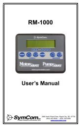
Remote Monitoring DevicesAvailable <strong>Model</strong>s:RM-1000RM-1000 NEMA 4FeaturesDisplays:• Individual line currents and average current• Current unbalance• Individual phase voltages and average voltage• Voltage unbalance• Present fault trip reason and restart timer status• Last four faults• MotorSaver ® and/or PumpSaver ® setpoints• Run-hours on each motor• Warning of pending (imminent) faultsThe RM-1000is a motor-monitoring device to be used in conjunction with <strong>SymCom</strong>’s <strong>Model</strong> <strong>777</strong>MotorSaver ® , <strong>Model</strong> <strong>777</strong>-<strong>KW</strong>/<strong>HP</strong> PumpSaver ® , <strong>Model</strong> 77C MotorSaver ® and <strong>Model</strong> 601MotorSaver ® . The RM-1000/<strong>777</strong> motor management system combines unsurpassedelectronic motor protection and critical, user-friendly motor monitoring.The RM-1000 improvessafety for service and operations personnel by allowing them to control and monitor the device withoutopening the control panel. Using the RM-1000 is a simple, cost-effective method of satisfying thenew requirements for arc-flash safety.The RM-1000 can monitor up to 16 MotorSaver ® and/or PumpSaver ® units through an RS-485network using Modbus RTU protocol. A second communication port allows monitoring and controlfrom a computer, PLC, DCS or SCADA system. Up to 99 MotorSaver ® and/or PumpSaver ® unitscan be accessed from the host computer or PLC with the RM-1000 acting as a repeater for anyof its motor protectors. In addition to the monitoring functions, the RM-1000 can reset a trippedMotorSaver ® or PumpSaver ® .The RM-1000 is environmentally protected and is easily mounted on the front of a panel or motorcontrol center. The enclosure and keypad assembly is water and ultraviolet light resistant. Theenclosure is NEMA 3R or NEMA 4X (optional) rated. The RM-1000 also has a wideoperating temperature range of -40° to 70°C (-40° to 158°F).See Appendix A, Figure 3 for a typical wiring diagram.Controls:• Reset run-hour meter• Reset MotorSaver ® or PumpSaver ®• Clear last fault in MotorSaver ® or PumpSaver ®• Change setpoints from the RM-1000Convenience:• Power from RS485MS-2W communications module• Monitor up to 16 <strong>777</strong>s with one display• NEMA 3R outdoor ratedSpecificationsControl Power • • • • • 12-24VDC (Supplied by RS485MS-2W)Power Consumption• 100mA (max.)Communication Port #1 for <strong>777</strong>(s) • • • • • Port #2 for PC, PLC, etc.Baud Rate • • • • • • • • • 9600 • • • • • • • • • • • • • • • • • 300-28800Setup • • • • • • • • • • • • None, Odd, or Even Parity • • • None, Odd, or Even Parity• • • • • • • • • • • • • • 1 or 2 Stop Bits • • • • • • • • • • 1 or 2 Stop BitsProtocol • • • • • • • • • • Modbus RTU • • • • • • • • • • • • Modbus RTUSerial Interface • • • • • • RS-485 • • • • • • • • • • • • • • • • RS-485Available Addresses • • • 1-99 (max 16 per RM-1000) • • Responds to all port #1 addressesEnvironmentClass of Protection • • • NEMA 3R and UL type 12, NEMA 4X (optional)Ambient OperatingTemperature• • • • • • • • -40˚ to 70˚C (-40˚ to 158˚F)Ambient StorageTemperature• • • • • • • • -40˚ to 70˚C (-40˚ to 158˚F)Humidity • • • • • • • • • • Up to 85%, non-condensingSafety MarksUL• • • • • • • • • • • • • UL508CE• • • • • • • • • • • • • IEC 60947-6-2EnclosureDimensions • • • • • • • • 3.619" H x 4.544" W X 0.9" DWeight • • • • • • • • • • • 6 oz.Material• • • • • • • • • • • Black polycarbonateDisplay • • • • • • • • • • Liquid Crystal with extended temp. rangeSize • • • • • • • • • • • • • 2 rows x 16 charactersKeypad • • • • • • • • • • Six 0.5" stainless steel dome buttons for tactile feedbackMechanical Life • • • • • • 100,000 actuationsOverlay Material • • • • • PolyesterUV Exposurew/o degradation • • • • • 2000 hrsTerminal • • • • • • • • • Depluggable terminal blockPanel Thickness • • • • 0.030" min, 0.120" maxwww.symcom.com • tel: 605-348-5580 800-843-8848 • fax: 605-348-56859
RM-2000The RM-2000is a motor-monitoring device to be used in conjunction with <strong>SymCom</strong>’s <strong>Model</strong> <strong>777</strong> productline.The RM-2000/<strong>777</strong> motor management system combines unsurpassed electronicmotor protection and critical, user-friendly motor monitoring.The RM-2000 has membrane keypad controls which allow both monitoring andcontrol of a <strong>777</strong> MotorSaver ® through an RS-485 network using Modbus RTU protocol.A second communication port is available to allow monitoring and control of up to 99RM-2000 devices from a PLC, DCS, or SCADA system or a PC with Solutions softwareinstalled.The RM-2000 is environmentally protected and is easily mounted on the frontof a panel or motor control center.See Appendix A, Figure 4 for a typical wiring diagram.Available <strong>Model</strong>s:RM-2000RM-2000 CBM+RM-2000-RTDWFeaturesDisplays:• Average current, individual line currents, and current unbalance• Current to ground• Average voltage, line-line voltages, and voltage unbalance• Instantaneous power• Power factor• Last four faults• All parameters programmed into <strong>777</strong> MotorSaver ®• Remaining restart delay timesControls:• Start and stop buttons• Key lock input to prevent setpoint changes• Change <strong>777</strong> setpoints from keypadThe RM-2000 is also equipped with a real-time clock, which allows access tothe following motor management information (most readings can be reset):• Total motor run-time• Time and date of last four faults, along with voltage and current at time of trip• Time and date of last 10 motor starts• Total number of motor restarts• Minimum time between any two starts with time and date• Run-time since last start• kWh consumed• kVARs consumedSpecificationsControl Voltage • • • • • • • • • • • 115VAC ±10%; 50/60HzTransient Protection (Internal) • 2500V for 10msPower Consumption • • • • • • • • 3 Watts (max.)Communication • • • • • • • • • • • 1 Port for <strong>777</strong> 1 Port for PC, PLC, etc.Baud Rate• • • • • • • • • • • • • • • • • 9600 300-28800Setup • • • • • • • • • • • • • • • • • • • Even ParityNone, Odd, or Even• • • • • • • • • • • • • • • • • • • • • • 1 Stop BitParity 1 or 2 Stop BitsProtocol • • • • • • • • • • • • • • • • • Modbus RTU Modbus RTUSerial Interface • • • • • • • • • • • • • RS-485RS-485Available Addresses • • • • • • • • • • 01A01-A99Real-time ClockBattery Back-up Life • • • • • • • • • • 10 years @ 25˚C without external powerLast fault memory • • • • • • • • • • • Stores up to 4 faults with time and date stamp,• • • • • • • • • • • • • • • • • • • • • • includes voltages and currents at time of tripConfiguration • • • • • • • • • • • • • • Two independent electro-mechanical form C (SPDT)Contact Material. • • • • • • • • • • • • Silver/Tin OxidePilot Duty Rating.• • • • • • • • • • • • 240VA @ 120VACGeneral Purpose Rating• • • • • • • • 5A @ 120VACEnvironmentClass of Protection• • • • • • • • • • • NEMA 3RAmbient Operating Temp. • • • • • • -40˚ to 70˚C (-40˚ to 158˚F)Ambient Storage Temp. • • • • • • • • -40˚ to 70˚C (-40˚ to 158˚F)Humidity • • • • • • • • • • • • • • • • • Up to 85%, non-condensingSafety MarksUL • • • • • • • • • • • • • • • • • • • UL508CE • • • • • • • • • • • • • • • • • • • IEC 60947-6-2EnclosureDimensions• • • • • • • • • • • • • • • • 6" W x 6 3 /8" H x 1 1 /16" DWeight • • • • • • • • • • • • • • • • • • 1.2 lbs.Material • • • • • • • • • • • • • • • • • • Black polycarbonateDisplay • • • • • • • • • • • • • • • • • • Liquid crystal with extended temp. rangeSize • • • • • • • • • • • • • • • • • • • • 2 rows x 20 charactersLighting • • • • • • • • • • • • • • • • • • LED BacklightKeypad• • • • • • • • • • • • • • • • • • Eight 0.5" stainless steel dome buttons for tactile feedbackMechanical Life • • • • • • • • • • • • • 100,000 actuationsOverlay Material • • • • • • • • • • • • PolyesterUV Exposure w/o degradation • • • • 2000 hrs.Terminal • • • • • • • • • • • • • • • • Depluggable terminal block10 www.symcom.com • tel: 605-348-5580 800-843-8848 • fax: 605-348-5685
Solutions SoftwareSolutions is a software application that provides the ability toconfigure and monitor Modbus (Solutions-M) or DeviceNet ®(Solutions-D) networks. Solutions features include the ability tolog data, real time data, continuous fault and event monitoring,and intuitive device configuration and setup. Solutions-Msupports both RS-485 and TCP/IP networks (requires aModbus TCP to Modbus RTU converter). Solutions-D providessupport for all DeviceNet capable <strong>SymCom</strong> devices andmost other DeviceNet devices, including DeviceNet scanners.Requirements• Microsoft Windows XP or higher• Microsoft .net Framework 2.0 (provided with Solutions)• 300 MB of hard drive space• RS-485 to RS-232 converter (with 1 available serial port) for Solutions-M orRS-485 to USB converter (with 1 available USB port) for Solutions-M• USB to CAN converter (with 1 available USB port) for Solutions-DAvailable <strong>Model</strong>s:Solutions-MSolutions-Dwww.symcom.com • tel: 605-348-5580 800-843-8848 • fax: 605-348-568511
Three-Phase Voltage MonitorsAll <strong>SymCom</strong> voltage monitors are microcontroller based and are factory calibrated for highly accurate and precise voltagemeasurements to provide high sensitivity while minimizing nuisance tripping.The high accuracy and precision of these devicesallows them to detect a single-phase condition or voltage unbalance even with regenerated voltages present.Uncalibrated devices require low sensitivity to voltage faults to prevent nuisance trips, thus may not trip in the presence ofregenerated voltages.<strong>SymCom</strong> voltage monitors are built with transformer power supplies which makes them highly resistant to damage causedby voltage transients on the power system that may be caused by switching transients or lightning. Other types of powersupplies such as switching, resistor limited and capacitor limited are typically more easily damaged by transients.Features• Monitor 3-phase voltage• Mounted in panel• Monitor for phase reversalProtects 3-Phase motors from:• High and low voltage• Voltage unbalance• Loss of any phase (single-phasing)• Phase-reversal• Contact failure• Rapid cycling12 www.symcom.com • tel: 605-348-5580 800-843-8848 • fax: 605-348-5685
3-Phase Voltage MonitorsProduct Selection MatrixMODEL80102A102A-2102A-3102A-9102-600201A201A-9201A-AU201-575-AU202202-RP202-575-RP250A250-100250-600350-200350-200-2350-200-2-6350-200-2-8*350-200-2-9350-400350-400-2350-400-2-5350-400-2-6350-400-2-8*350-400-2-9350-400-5350-600350-600-2350-600-2-6350-600-2-8*350-600-2-9355-200355-400355-400-5355-600455455-575455-480R460460-OEM460-L460L-OEM460-14460-575-14460-15460-MR460-575460-VBM460-400Hz601**601-HVR**601-575**Low VoltagePhase ReversalVoltage UnbalanceSingle PhaseFrequency ShiftHigh VoltageContact FailureRapid CyclingDiagnostic LEDsVariable Trip PointVariable Restart DelayVariable Trip DelayVariable Voltage UnbalanceManual ResetDPDT Relay10 Amp General Purpose15 Amp General Purpose470VA @ 600VAC Pilot Duty480VA @ 240VAC Pilot Duty8 Amp General Purpose NO8 Amp General Purpose NCDual Range 190-480VAC100V Range 95-120VAC200V Range 190-240VAC400V Range 380-480VAC600V Range 475-600VACVoltage Band Monitor* These units are not equipped with manual reset as indicated on the label.** Indicates units have RS-485 Modbus communication capability and digital displayIndicates two relayswww.symcom.com • tel: 605-348-5580 800-843-8848 • fax: 605-348-568513
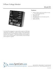
<strong>Model</strong> 80The <strong>Model</strong> 80is designed to continuously monitor phase rotation of 3-phase systems.Critical applications include fan motors, scroll compressors, grinders, conveyorsystems, elevators and escalators. A solid-state phase sensing circuit drives aninternal electro-mechanical relay which is energized when proper phase rotationis applied. An LED indicator illuminates when phase rotation is correct.Reset is automatic.See Appendix A, Figures 5 & 6 for typical wiring diagrams.Part No. 80Features• Run light to indicate ABC sequence• Universal input voltage• CSA & CSA-NRTL/C approvedProtects 3-Phase motors from:• Reverse phaseSpecificationsInput Power• 3-phase line voltage• • • • • • • • • • • • • 171-264VAC (200V Input)• • • • • • • • • • • • • • • • • • • • • • • • • • 342-528VAC (400V Input)• Frequency• • • • • • • • • • • • • • • • • • • 50/60 Hz• Power Consumption • • • • • • • • • • • • 5 Watts (max.)Ouput Ratings• Relay contact rating• • • • • • • • • • • • • 10 Amps Gen. Purpose at 240VACResponse Time• • • • • • • • • • • • • • • • • 0.5 secondEnvironmental• Temperature Range • • • • • • • • • • • • • -20 to 60°C14 www.symcom.com • tel: 605-348-5580 800-843-8848 • fax: 605-348-5685
<strong>Model</strong> 102AThe <strong>Model</strong> 102Ais an auto-ranging voltage monitor designed to protect 3-phase motorsregardless of size. It is used on 190-480VAC, 50*/60Hz motors toprevent damage caused by incoming power problems.Available <strong>Model</strong>s:102A102A-2102A-3102A-9102-600A unique microcontroller-based voltage and phase-sensing circuitconstantly monitors the 3-phase voltages to detect harmful power lineconditions.When a harmful condition is detected, the MotorSaver's outputrelay is deactivated after a specified trip delay. The output relay reactivatesafter power line conditions return to acceptable levels. The <strong>Model</strong> 102Aincludes advanced single LED diagnostics. Five different light patternsdistinguish between faults and normal conditions.See Appendix A, Figures 7 & 8 for typical wiring diagrams.Features2 - Variable Restart Delay (Manual, 2-300 seconds)3 - Variable Trip Delay (2-30 seconds)9 - High Voltage Detection• Low voltage trip• Optional high voltage trip• Single-phase trip• Reverse-phase trip• Fixed 6% voltage unbalance trip• Single LED diagnostics• Separate indicators for:Power-up restart delayReverse-phase tripGood voltage/relay energizedUnbalance/single-phase tripHigh/low voltage tripSpecifications3-Phase Line Voltage102A• • • • • • • • • • • • • • • • • • • • • • • • 190-480VAC102-600 • • • • • • • • • • • • • • • • • • • • • • 475-600VACFrequency • • • • • • • • • • • • • • • • • • • 50*/60HzLow Voltage (% of setpoint)Trip • • • • • • • • • • • • • • • • • • • • • • • • 90%Reset • • • • • • • • • • • • • • • • • • • • • • • 93%Voltage Unbalance (NEMA)Trip • • • • • • • • • • • • • • • • • • • • • • • • 6%Reset • • • • • • • • • • • • • • • • • • • • • • • 4.5%Trip Delay TimeLow/High Voltage • • • • • • • • • • • • • • • • 4 seconds (standard)Unbalance & Phasing Faults• • • • • • • • • • 2 secondsRestart Delay TimeAfter a Fault • • • • • • • • • • • • • • • • • • • 2 seconds (standard)After a Complete Power Loss• • • • • • • • 2 seconds (standard)Output Contact RatingSPDT • • • • • • • • • • • • • • • • • • • • • • • 480VA @ 240VAC Pilot Duty• • • • • • • • • • • • • • • • • • • • • • • • • 10A @ 240VAC General PurposeTransient Protection (Internal) • • • • IEC 1000-4-5; 1995 ±6kVPower Consumption • • • • • • • • • • • 5 Watts (max.)Weight • • • • • • • • • • • • • • • • • • • • • 14 oz.Available Options(2) Adjustable Restart Delay • • • • • • • • • Manual, 2-300 seconds(3) Adjustable Trip Delay • • • • • • • • • • • 2-30 seconds(Phasing and unbalance trip delay remains at 2 seconds)(9) High Voltage Operating PointsTrip (% of Setpoint) • • • • • • • • • • • • • • 110%Reset (% of Setpoint) • • • • • • • • • • • • • 107%*Note: 50Hz will increase all delay timers by 20%.www.symcom.com • tel: 605-348-5580 800-843-8848 • fax: 605-348-568515
<strong>Model</strong> 201AThe <strong>Model</strong> 201Ais an auto-ranging, 8-pin, plug-in style voltage monitor designed to protect 3-phasemotors regardless of size. It is used on 190-480VAC, 50*/60Hz motors to preventdamage caused by incoming power problems.The <strong>Model</strong> 201A includes advancedsingle LED diagnostics, where five different light patterns distinguish between faultsand normal conditions.This unique microcontroller-based voltage and phase-sensing device constantlymonitors the 3-phase voltages to detect harmful power line conditions. When aharmful condition is detected, the MotorSaver's output relay is deactivated after aspecified trip delay. The output relay reactivates after power line conditions returnto acceptable levels.See Appendix A, Figures 9 & 10 for typical wiring diagrams.Available <strong>Model</strong>s201A201A-9Features• Low voltage trip• Single-phase trip• Reverse-phase trip• Fixed 6% voltage unbalance trip• Single LED diagnostics• High voltage trip (-9 option)• Separate indicators for:Power-up restart delayReverse-phase tripGood voltage/relay energizedUnbalance/single-phase tripHigh/low voltage tripMust use <strong>Model</strong> OT08 socket for UL Rating!Specifications3-Phase Line Voltage • • • • • • • • • • • • • • • • • • 190-480VACFrequency • • • • • • • • • • • • • • • • • • • • • • • • • 50*/60HzLow Voltage (% of setpoint)Trip • • • • • • • • • • • • • • • • • • • • • • • • • • • • • • 90%Reset • • • • • • • • • • • • • • • • • • • • • • • • • • • • • 93%Voltage Unbalance (NEMA)Trip • • • • • • • • • • • • • • • • • • • • • • • • • • • • • • 6%Reset • • • • • • • • • • • • • • • • • • • • • • • • • • • • • 4.5%Optional High Voltage (% of setpoint)Trip • • • • • • • • • • • • • • • • • • • • • • • • • • • • • • 110%Reset • • • • • • • • • • • • • • • • • • • • • • • • • • • • • 107%Trip Delay TimeHigh/Low Voltage Fault • • • • • • • • • • • • • • • • • • 4 secondsUnbalance & Phasing Faults • • • • • • • • • • • • • • • 2 secondsRestart Delay TimeAfter a Fault • • • • • • • • • • • • • • • • • • • • • • • • • 2 secondsAfter a Complete Power Loss • • • • • • • • • • • • • 2 secondsOutput Contact RatingSPDT• • • • • • • • • • • • • • • • • • • • • • • • • • • • • • 480VA @ 240VAC Pilot Duty• • • • • • • • • • • • • • • • • • • • • • • • • • • • • • • • • 10A @ 240VAC General PurposeTransient Protection (Internal) • • • • • • • • • • 2500V for 10 msPower Consumption • • • • • • • • • • • • • • • • • • 5 Watts (max.)Weight • • • • • • • • • • • • • • • • • • • • • • • • • • • 9 oz.Socket Available • • • • • • • • • • • • • • • • • • • • • <strong>Model</strong> OT08 (UL Rating 600V)The 600V socket can be surface mounted or installed on DIN Rail.*Note: 50Hz will increase all delay timers by 20%.16 www.symcom.com • tel: 605-348-5580 800-843-8848 • fax: 605-348-5685
<strong>Model</strong> 201A-AUThe <strong>Model</strong> 201A-AUis an auto-ranging, 8-pin, plug-in style voltage monitor designed to protect3-phase motors regardless of size. It is used on 190-480VAC, 50*/60Hzmotors to prevent damage caused by incoming power problems. The <strong>Model</strong>201A-AU includes advanced single LED diagnostics, where five different lightpatterns distinguish between faults and normal conditions. Adjustment knobsallow the user to set a 1-30 second trip delay, a manual restart or1-500 secondrestart delay and a 2-8% voltage unbalance trip point.This unique microcontroller-based voltage and phase-sensing device constantlymonitors the 3-phase voltages to detect harmful power line conditions.When a harmful condition is detected, the MotorSaver's output relay isdeactivated after a specified trip delay.The output relay reactivates after powerline conditions return to acceptable levels.See Appendix A, Figures 11 & 12 for typical wiring diagrams.Available <strong>Model</strong>s:201A-AU201-575-AU201A-AU-OT (sold with OT08 socket)201-575-AU-OT (sold with OT08 socket)Features• DIN rail or surface mountable• Manual reset option provideslast fault detection• Auto-ranging voltage• Advanced LED diagnostics• Adjustable voltage unbalancetrip setting• Adjustable trip & restartdelay settingsProtects 3-Phase motors from:• Loss of any phase (single-phasing)• Low voltage• High voltage• Voltage unbalance• Phase reversal• Rapid cyclingMust use <strong>Model</strong> OT08 socket for UL Rating!Specifications3-Phase Line Voltage201A-AU • • • • • • • • • • • • • • • • • • • • • 190-480VAC201-575-AU • • • • • • • • • • • • • • • • • • • • 475-600VACFrequency • • • • • • • • • • • • • • • • • • • • 50*/60HzLow Voltage (% of setpoint)Trip • • • • • • • • • • • • • • • • • • • • • • • • • 90% ±1%Reset • • • • • • • • • • • • • • • • • • • • • • • • 93% ±1%High Voltage (% of setpoint)Trip • • • • • • • • • • • • • • • • • • • • • • • • • 110% ±1%Reset • • • • • • • • • • • • • • • • • • • • • • • • 107% ±1%Voltage Unbalance (NEMA)Trip • • • • • • • • • • • • • • • • • • • • • • • • • 2-8% adjustableReset • • • • • • • • • • • • • • • • • • • • • • • • Trip Setting Minus 1% (5-8%)• • • • • • • • • • • • • • • • • • • • • • • • • • • • Trip Setting Minus .5% (2-4%)Trip Delay TimeHigh, Low and Unbalanced Voltage • • • • • • 1-30 seconds adjustableSingle-Phasing Faults • • • • • • • • • • • • • • 1 second fixedRestart Delay TimeAfter a Fault • • • • • • • • • • • • • • • • • • • Manual, 1-500 seconds adjustableAfter a Complete Power Loss • • • • • • • • Manual, 1-500 seconds adjustableOutput Contact Rating1-Form C • • • • • • • • • • • • • • • • • • • • • 10A @ 240VAC General Purpose• • • • • • • • • • • • • • • • • • • • • • • • • • • • 480VA @ 240VAC Pilot Duty, B300Power Consumption • • • • • • • • • • • • 5 Watts (max.)Weight • • • • • • • • • • • • • • • • • • • • • • 9 oz.Enclosure • • • • • • • • • • • • • • • • • • • • PolycarbonateSafety Marks•UL • • • • • • • • • • • • • • • • • • • • • • • • • UL508•CE • • • • • • • • • • • • • • • • • • • • • • • • • IEC 60947-6-2Standards Passed•Electrostatic Discharge (ESD) • • • • • • • • IEC 1000-4-2, Level 3, 6kV contact, 8kV air•Radio Frequency Immunity, Radiated• • • • 150 MHz, 10V/m•Fast Transient Burst • • • • • • • • • • • • • • IEC 1000-4-4, Level 3, 3.5kV input power & controlsSurge•IEC• • • • • • • • • • • • • • • • • • • • • • • • • IEC 1000-4-5, Level 3, 4kV line-to-line;• • • • • • • • • • • • • • • • • • • • • • • • • • • Level 4, 4kV line-to-ground•ANSI/IEEE • • • • • • • • • • • • • • • • • • • • C62.41 Surge and Ring Wave Compliance• • • • • • • • • • • • • • • • • • • • • • • • • • • to a level of 6kV line-to-line•Hi-potential Test • • • • • • • • • • • • • • • • Meets UL508 (2 x rated V +1000V for 1 minute)EnvironmentalTemperature Range • • • • • • • • • • • • • • • Ambient Operating: -40° to 70°C (-40° to 158°F)• • • • • • • • • • • • • • • • • • • • • • • • • • • Ambient Storage: -40° to 80°C (-40° to 176°F)Relative Humidity • • • • • • • • • • • • • • • • 10-95%, non-condensing per IEC 68-2-3Socket Available• • • • • • • • • • • • • • • • <strong>Model</strong> OT08 (UL Rating 600V)The 600V socket can be surface mounted or installed on DIN Rail.*Note: 50Hz will increase all delay timers by 20%.www.symcom.com • tel: 605-348-5580 800-843-8848 • fax: 605-348-568517
<strong>Model</strong> 355The <strong>Model</strong> 355is a 3-phase voltage monitor with adjustable trip and restart delay, adjustablevoltage unbalance and multiple diagnostic lights. It is perfect for heavy-dutyapplications that need both protection and simple user-friendly diagnostics.Applications include pump panels, commercial HVAC, oil rigs and others.The <strong>Model</strong> 355 uses microcontroller technology to monitor incomingvoltage, and de-energize its output relay if power problems exist.The <strong>Model</strong> 355 can protect motors from damage caused by single-phasing, highand low voltage, phase reversal and voltage unbalance. It has four diagnostic LEDsthat clearly show overvoltage, undervoltage, voltage unbalance, reverse-phase andnormal conditions.Available <strong>Model</strong>s:355-200355-400355-400-5355-600The <strong>Model</strong> 355-200 is equipped with a heavy-duty 10A general purpose SPDTrelay. The <strong>Model</strong> 355-400 and 355-600 are equipped with a 470VA @ 600VACpilot duty SPDT relay. A high voltage (600V) DPDT relay output option isavailable with the 400V model.See Appendix A, Figures 17 & 18 for typical wiring diagrams.Features• Standard high voltage relay for 400V and 600V ranges• Multiple LEDs provide diagnostics• Adjustable trip and restart delaysProtects 3-Phase motors from:• Loss of any phase (single-phasing)• Low voltage• High voltage• Voltage unbalance (adjustable setpoint)• Phase reversalSpecifications3-Phase Line Voltage355-200 • • • • • • • • • • • • • • • • • • • • 190-240VAC355-400 • • • • • • • • • • • • • • • • • • • • 380-480VAC355-600 • • • • • • • • • • • • • • • • • • • • 475-600VAC(Specify voltage range)Frequency • • • • • • • • • • • • • • • • • • 50*/60HzLow Voltage (% of setpoint)Trip• • • • • • • • • • • • • • • • • • • • • • • 90% ±1%Reset • • • • • • • • • • • • • • • • • • • • • 93% ±1%High Voltage (% of setpoint)Trip• • • • • • • • • • • • • • • • • • • • • • • 110% ±1Reset • • • • • • • • • • • • • • • • • • • • • 107% ±1%Voltage Unbalance (NEMA)Trip• • • • • • • • • • • • • • • • • • • • • • • 2-8% adjustableReset • • • • • • • • • • • • • • • • • • • • • Trip setting minus 1%Trip Delay TimeLow & High Voltage and Unbalance• • • 2-30 seconds adjustableSingle-phasing Faults (>25% UB) • • • • 2 secondsRestart Delay TimeAfter a Fault or Power Loss • • • • • • • Manual, 2-300 seconds adjustableOutput Contact RatingSPDT (355-200) • • • • • • • • • • • • • • • 480VA at 240VAC Pilot Duty• • • • • • • • • • • • • • • • • • • • • • • • • • 10A General PurposeSPDT (355-400, 355-600) • • • • • • • • • 470VA @ 600VAC Pilot Duty10A General Purpose or• • • • • • • • • • • • • • • • • • • • • • • • • 1hp @ 240VACDPDT (-5 Option)• • • • • • • • • • • • • • 2-10A General Purpose• • • • • • • • • • • • • • • • • • • • • • • • • 470VA @ 600VAC Pilot DutyTransient Protection (Internal) • • 2500V for 10 msRepeat AccuracyFixed Conditions • • • • • • • • • • • • • • ±0.1%Power Consumption • • • • • • • • • 6 Watts (max.)Weight • • • • • • • • • • • • • • • • • • • 1 lb.*Note: 50Hz will increase all delay times by 20%.www.symcom.com • tel: 605-348-5580 800-843-8848 • fax: 605-348-568521
<strong>Model</strong> 455The <strong>Model</strong> 4553-phase voltage monitor combines load and line side monitoring to alert the userof contactor failure or impending contactor failure.The line side monitoring willprotect the motor from damaging line side conditions prior to the motor starting.With other line-load side voltage monitors, the motor must be started before avoltage problem is detected.With the <strong>Model</strong> 455, the motor is fully protected atall times.The motor will not start when a power problem is present.The <strong>Model</strong> 455 now has an infrared LEDto communicate with the new Informer-MS.Just aim the handheld diagnostic tool at the 455to get valuable information such as real-time voltage andvoltage unbalance on both line and load sides; motor runhours; last 20 faults; last 32 motor starts; high and lowvoltage trip points; voltage unbalance trip point; restartand trip delay settings; MotorSaver ® status and more!Available <strong>Model</strong>s:455455-480R455-575SpecificationsThe <strong>Model</strong> 455 automatically senses whether it is connected to a 200V, 300Vor 400V system.An adjustment is provided to set the nominal line voltage from190-240 or 380-480VAC. Other adjustments include a 2-30 second trip delay,a 2-300 second restart delay (and manual restart), and a voltage unbalance trippoint adjustment from 2-8%.Four LEDs indicate the status of the <strong>Model</strong> 455: run light, undervoltage,overvoltage, and phasing fault. The <strong>Model</strong> 455 is the only load and line sidemonitor on the market that does not require a separate power source for itselectronics, making it much easier to install.See Appendix A, Figures 19 & 20 for typical wiring diagrams.Features• Load side monitoring of contactor• Multiple LEDs for diagnostics, special indicators for overvoltage,undervoltage and phasing faults• Prevents rapid cycling by monitoring contactor or starter• Infrared LED to communicate with Informer-MSProtects 3-Phase motors from:• Contact failure• Loss of any phase (single-phasing) on the load or line side• Low voltage• High voltage• Voltage unbalance (adjustable setpoint)• Phase reversal• Rapid cycling3-Phase Line Voltage455 • • • • • • • • • • • • • • • • • • • • • • • 190-480VAC455-575 • • • • • • • • • • • • • • • • • • • • 475-600VAC455-480-R • • • • • • • • • • • • • • • • • • • 380-480VACFrequency • • • • • • • • • • • • • • • • • • 50*/60HzLow Voltage (% of setpoint)Trip • • • • • • • • • • • • • • • • • • • • • • • 90% ±1%Reset • • • • • • • • • • • • • • • • • • • • • • 93% ±1%High Voltage (% of setpoint)Trip • • • • • • • • • • • • • • • • • • • • • • • 110% ±1%Reset • • • • • • • • • • • • • • • • • • • • • • 107% ±1%Voltage Unbalance (NEMA)Trip • • • • • • • • • • • • • • • • • • • • • • • 2-8% adjustableReset • • • • • • • • • • • • • • • • • • • • • • Trip setting minus 1%Trip Delay TimeLow & High Voltage and Unbalance • • • 2-30 seconds adjustableSingle-phasing Faults (>25% UB) • • • • • 2 seconds fixedRestart Delay TimeAfter a Fault• • • • • • • • • • • • • • • • • • Manual, 2-300 seconds adj.After a Complete Power Loss • • • • • • Manual, 2-300 seconds adj.After a Motor Shut-down • • • • • • • • • Manual, 2-300 seconds adj.Output Contact RatingSPDT • • • • • • • • • • • • • • • • • • • • • • 480VA @ 240VAC Pilot Duty• • • • • • • • • • • • • • • • • • • • • • • • • • 10A General PurposeSPDT High Voltage Relay (-480R) • • • • 470VA @ 600VAC Pilot DutyTransient Protection (Internal)• • • IEC 1000-4-5;1995 ±6kVRepeat Accuracy•Fixed Conditions • • • • • • • • • • • • • • ±0.1%Power Consumption • • • • • • • • • • 6 Watts (max.)Weight • • • • • • • • • • • • • • • • • • • • 14 oz.*Note: 50Hz will increase all delay times by 20%.22 www.symcom.com • tel: 605-348-5580 800-843-8848 • fax: 605-348-5685
Informer MSThe Informer-MSis a handheld diagnostic tool designed for use with MotorSaver ® <strong>Model</strong> 455*equipped with an infrared LED transmitter.The Informer-MS uses an infrared receiver to read valuable informationtransmitted from the <strong>Model</strong> 455*, which can be helpful for troubleshooting thesystem. A green communication status light indicates the Informer-MS is receivingdata from the MotorSaver ® . If communication is lost,the Informer-MS will display the last values it received.The Informer-MS displays:• Real-time, line and load side voltage• Real-time, line and load side voltage unbalance• Motor run hours• Last 20 faults• Last 32 motor starts• High and low voltage trip points• Voltage unbalance trip point• Restart and trip delay settings• Voltage at last fault* <strong>Model</strong> 455s manufactured after 03/01/06 are equipped with the infrared LED transmitter.<strong>Model</strong>s manufactured prior to this date are not compatible with the new Informer-MS.An infrared adapter can be purchased to allow communicationwith the <strong>Model</strong> 455 without opening the panel door.SpecificationsPowerInput • • • • • • • • • • • • 9 Volts DC (requires one 9-volt alkaline battery)Consumption • • • • • • 0.25 Watt (max.)Auto Shut-off • • • • • • 2 minutesOperating Temp. • • • • 0 to 60°CCommunicationSignal • • • • • • • • • • • • InfraredRange • • • • • • • • • • • 1-8 ft.Data Update • • • • • • •4 secondsAccuracyVoltage • • • • • • • • • • ±2%ResolutionVoltage • • • • • • • • • • 1.0VACDisplay • • • • • • • • • • • Liquid crystalSize • • • • • • • • • • • • • 2 rows x 16 charactersKeypad • • • • • • • • • • • Three 0.5” buttonsMechanical Life • • • • • 500,000 actuationsOverlay Material • • • • LexanEnclosureDimensions • • • • • • • • 5.50” H x 3.6” W x 1.125” DWeight • • • • • • • • • • • 6 oz. (w/out battery)Material • • • • • • • • • • Black ABSwww.symcom.com • tel: 605-348-5580 800-843-8848 • fax: 605-348-568523
<strong>Model</strong> 601The <strong>Model</strong> 601is a fully-programmable voltage monitor designed to protect 3-phase motors.It can be used as a stand-alone product or networked with an RM-1000,RM-2000, PLC, computer or SCADA system.When a harmful condition is detected, the MotorSaver's output relay isdeactivated after the specified trip delay. The output relay reactivates afterpower line conditions return to an acceptable level for the programmedrestart delay (RD2).Available <strong>Model</strong>s:601601-HVR601-575The following 11 setpoints can be viewed from the 3-digit LED display orfrom a networked device: low voltage, high voltage, voltage unbalance, lowfrequency, high frequency, trip delay for voltage/frequency faults, trip delay forsingle-phase faults, rapid-cycle timer (RD1), restart delay after all faults (RD2),type of restart after all faults (manual or automatic), and RS-485 address. Sixparameters can be viewed as the motor is running: L1-L2 voltage,L2-L3 voltage, L1-L3 voltage, average voltage, percent voltage unbalance,and frequency.When used with the RS485MS or RS485MS-2W communications module,the <strong>Model</strong> 601 can communicate with most modbus RTU master devices.Voltage conditions can be monitored and setpoints can be changed remotelyusing <strong>SymCom</strong>’s Solutions software, an RM-1000, RM-2000, or other device.See Appendix A, Figure 23 for a typical wiring diagram.SpecificationsNominal Input Voltage601 • • • • • • • • • • • • • • • • • • • • • • 190-480VAC601-HVR • • • • • • • • • • • • • • • • • • 380-480VAC601-575 • • • • • • • • • • • • • • • • • • • 500-600VACFrequency • • • • • • • • • • • • • • • • • 50*/60HzProgrammable Operating PointsLV - Low Voltage Threshold • • • • • • • 170V (450V**) - HV SettingHV- High Voltage Threshold • • • • • • • LV Setting - 528V (660V**)VUB - Voltage Unbalance Threshold• • 2-15% or offLF - Low Frequency Threshold • • • • • 35Hz - HF SettingHF - High Frequency Threshold • • • • LF Setting - 75HzTD1 - Trip Delay for Voltage/Unbalance/Frequency Faults• • • • • • 1-50 secondsTD2 - Trip Delay forSingle-Phase Faults• • • • • • • • • • • • 1-50 secondsRD1 - Rapid-Cycle Timer • • • • • • • • 0, 2-500 secondsRD2 - Restart Delay After All Faults • 2-500 seconds#RF - Type of Restart• • • • • • • • • • • Manual or AutomaticADDR - RS-485 Address • • • • • • • • A01-A99Fixed Reset PointsOvervoltage Reset • • • • • • • • • • • • 97% of HV SettingLow Voltage Reset • • • • • • • • • • • • • 103% of LV SettingVoltage Unbalance Reset• • • • • • • • • UB Setting -1%Low Frequency Reset• • • • • • • • • • • LF Setting +0.6HzHigh Frequency Reset • • • • • • • • • • HF Setting -0.6HzPhysical SpecificationsOutput Contact Rating601, 601-575 • • • • • • • • • • • • • • • • 480VA @ 240VAC (Pilot Duty)601-HVR • • • • • • • • • • • • • • • • • • 470VA @ 600VAC (Pilot Duty)Transient Protection (Internal) • • • • • 2500 V for 10 msAccuracyVoltage • • • • • • • • • • • • • • • • • • • • ±1%Timing • • • • • • • • • • • • • • • • • • • • 5% ±1 secondRepeatabilityVoltage • • • • • • • • • • • • • • • • • • • • ±0.5%Temperature Range • • • • • • • • • • 0° to 70°CDimensions • • • • • • • • • • • • • • • • 3.0" H x 5.1" D x 3.6" WPower Consumption • • • • • • • • • 5 Watts (max.)Weight • • • • • • • • • • • • • • • • • • • 1.2 lbs.<strong>SymCom</strong>'s <strong>Model</strong> 601 can be preprogrammed prior to installation byapplying at least 120V to the L1 and L2 terminals.*Note: 50Hz will increase all delay timers by 20%**575V <strong>Model</strong>26 www.symcom.com • tel: 605-348-5580 800-843-8848 • fax: 605-348-5685
Single-Phase Voltage MonitorsAll of <strong>SymCom</strong>’s single-phase voltage monitors are micro-controller based and are factory calibrated for highly accurate and precise voltagemeasurements to provide high sensitivity while minimizing nuisance tripping.They are built with transformer power supplies, whichmakes them highly resistant to damage caused by voltage transients on the power system that may be caused by switching transientsor lightning. Other types of power supplies such as switching, resistor limited and capacitor limited are typically more easily damaged bytransients.Features• Monitor single-phase voltage• Panel mountedProduct Selection Matrix<strong>Model</strong>50R-11550R-115-250R-20050R-200-250R-200-350R-200-950R-200-2-950R-40050R-400-250R-400-350R-400-2-9201-100-SP201-200-SP201A-277-SP201-200-SP-T202-200-SP202-200-SP-NHV460-100-SP460-200-SPLow VoltageHigh VoltageVariable Restart DelayVariable Trip DelayManual Reset10 Amp General PurposeOT08 Socket Style470VA @ 600VAC Pilot Dutywww.symcom.com • tel: 605-348-5580 800-843-8848 • fax: 605-348-568527
<strong>Model</strong> 50RThe <strong>Model</strong> 50Rsingle-phase voltage monitor has a voltage-sensing circuit which constantlymonitors the single-phase power for a low voltage condition. Single-phasemotors on fans, compressors, air conditioners, heat pumps, well pumps,sump pumps, and small conveyor motors are all applicable to the <strong>Model</strong> 50R.Available <strong>Model</strong>s:50R-11550R-115-250R-20050R-200-250R-200-350R-200-2-950R-200-950R-40050R-400-250R-400-350R-400-2-9When a harmful condition is detected, the MotorSaver's output relay isdeactivated after a specified trip delay.The output relay reactivates afterpower line conditions return to an acceptable level for a specified amountof time (restart delay). The trip delay prevents nuisance tripping due torapidly fluctuating power line conditions.See Appendix A, Figure 24 for a typical wiring diagram.Optional Features• High voltage protection• Variable restart delay• Variable trip delay2 - Variable Restart Delay (Manual, 2-300 seconds)3 - Variable Trip Delay (2-30 seconds)9 - High Voltage DetectionSpecificationsLine Voltage50R-115 • • • • • • • • • • • • • • • 95-120VAC50R-200 • • • • • • • • • • • • • • • 190-240VAC50R-400** • • • • • • • • • • • • • • 380-480VAC**Comes standard with 470VA @ 600VAC relay.Frequency • • • • • • • • • • • • 50*/60HzLow VoltageTrip (% of setpoint) • • • • • • • • 90%Reset (% of setpoint) • • • • • • • 93%Delay Time (Nominal)Trip • • • • • • • • • • • • • • • • • • 4 secondsRestart (low voltage) • • • • • • • 2 secondsRestart (complete power loss) • 2 secondsOutputSPDT • • • • • • • • • • • • • • • • • 10A General Purpose or 480VA @ 240VAC Pilot DutyTransient Protection (Internal) • IEC 1000-4-5; 1995 ±6kVWeight • • • • • • • • • • • • • • • 1 lb.Safety Marks•UL • • • • • • • • • • • • • • • • • • • UL508•CE • • • • • • • • • • • • • • • • • • • IEC 60947-6-2Special OptionsVariable Time Delay Restart• • • Manual, 2-300 secondsVariable Trip Delay• • • • • • • • • 2-30 secondsHigh Voltage Operating Points (Option 9)Trip (% of Setpoint) • • • • • • • • 110%Reset (% of Setpoint) • • • • • • • 107%*Note: 50Hz will increase all delay timers by 20%28 www.symcom.com • tel: 605-348-5580 800-843-8848 • fax: 605-348-5685
<strong>Model</strong> 201-100-SPThe <strong>Model</strong> 201-100-SPis an octal-base, plug-in voltage monitor designed to protect single-phasemotors regardless of size. It is used on 95-480VAC, 50/60Hz motors toprevent damage caused by low voltage. High voltage protection is optional.Available <strong>Model</strong>s:201-100-SP201-200-SP201A-277-SP201-200-SP-TThe unique microcontroller-based voltage and voltage-sensing circuit constantlymonitors the voltage to detect harmful power line conditions.When a harmfulcondition is detected, the MotorSaver's output relay is deactivated after aspecified trip delay. The output relay reactivates after power line conditionsreturn to an acceptable level for 1 a specified amount of time (restart delay).The trip delay prevents nuisance tripping due to rapidly fluctuating powerline conditions.See Appendix A, Figure 25 for a typical wiring diagram.Pin-out 1Pin-out 2(View from back of unit.)Must use <strong>Model</strong> OT08 socket for UL Rating!SpecificationsSingle-Phase Line Voltage201-100-SP • • • • • • • • • • • • • • • • • • 95-120VAC201-200-SP, 201-200-SP-T• • • • • • • • • 190-240VAC201A-277-SP• • • • • • • • • • • • • • • • • 190-277VACFrequency • • • • • • • • • • • • • • • • • 50/60HzLow Voltage (% of setpoint)Trip • • • • • • • • • • • • • • • • • • • • • • 90%Reset • • • • • • • • • • • • • • • • • • • • • 93%Optional High Voltage (% of setpoint)Trip • • • • • • • • • • • • • • • • • • • • • • 110%Reset • • • • • • • • • • • • • • • • • • • • • 107%Trip Delay TimeHigh/Low Voltage Fault • • • • • • • • • • 4 seconds1Restart Delay TimeAfter a Fault • • • • • • • • • • • • • • • • 2 secondsAfter a Complete Power Loss • • • • • 2 secondsOutput Contact Rating (SPDT)Pilot Duty • • • • • • • • • • • • • • • • • • 480VA @ 240VACGeneral Purpose • • • • • • • • • • • • • • 10A @ 240VACTransient Protection (Internal) • • 2500V for 10 msPower Consumption • • • • • • • • • 5 Watts (max.)Weight • • • • • • • • • • • • • • • • • • • 9 oz.Socket Available • • • • • • • • • • • • <strong>Model</strong> # OT08 (UL Rating 600V)The 600V socket can be surface mounted or installed on DIN Rail.www.symcom.com • tel: 605-348-5580 800-843-8848 • fax: 605-348-568529
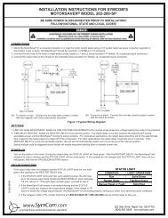
<strong>Model</strong> 202-200-SPThe <strong>Model</strong> 202-200-SPvoltage monitor is designed to protect single-phase motors regardless of size.It can be used with 190V-240VAC, 50/60Hz motors to preventdamage caused by incoming power problems.A unique microcontroller-based voltage-sensing circuit constantly monitorsthe voltage to detect harmful power line conditions. When a harmfulcondition is detected, the MotorSaver's output relay is deactivated after aspecified trip delay.The output relay reactivates after power line conditionsreturn to an acceptable level for a specified amount of time (restart delay).The trip delay prevents nuisance tripping due to rapidly fluctuating powerline conditions.Available <strong>Model</strong>s:202-200-SP202-200-SP-NHVFeatures• Protects single-phase motors from:High and low voltageRapid cycling• Quick mounting with single screw• Small package, ideal for assembly into panels• Standard 1/4” quick connectsSpecificationsSingle-Phase Line Voltage202-200-SP, 202-200-SP-NHV • • • 190-240VACFrequency • • • • • • • • • • • • • • 50*/60HzLow Voltage (% of setpoint)Trip • • • • • • • • • • • • • • • • • • • 90%Reset • • • • • • • • • • • • • • • • • • 93%High Voltage (% of setpoint) (Not available on -NHV model)Trip • • • • • • • • • • • • • • • • • • • 110%Reset • • • • • • • • • • • • • • • • • • 107%Trip Delay TimeHigh and Low Voltage • • • • • • • • 4 secondsRestart Delay TimeAfter a fault orcomplete power loss • • • • • • • • Manual, 2-300 seconds adjustableOutput Contact RatingSPDT • • • • • • • • • • • • • • • • • • 480VA @ 240VAC Pilot Duty• • • • • • • • • • • • • • • • • • • • • • or 10A @ 240VAC Gen. PurposeTransient Protection • • • • • • IEC 1000-4-5, ±4kVPower Consumption • • • • • • 5 Watts (max.)Weight • • • • • • • • • • • • • • • • 8 oz.Trip & Reset Accuracy • • • • • ±1%Repeatability • • • • • • • • • • • • ±0.5%Input to Output Dielectric • • 1960 Vrms (min.)Termination • • • • • • • • • • • • • 0.25" Male Quick ConnectHumidity • • • • • • • • • • • • • • • 95% Relative Non CondensingOperating Temperature • • • • -40˚ to 70˚CCE PendingUL Recognized • • • • • • • • • • • File # E68520*Note: 50Hz will increase all delay timers by 20%.30 www.symcom.com • tel: 605-348-5580 800-843-8848 • fax: 605-348-5685
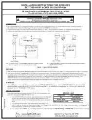
<strong>Model</strong> 460-100-SPThe <strong>Model</strong> 460-100-SPis designed to protect single-phase motors from damaging high and lowvoltage conditions. Adjustment knobs allow the user to set the nominal linevoltage from 190-240VAC and a 1-500 second restart delay. The variablerestart delay is also a power-up delay and can be utilized tostagger-start motors on the same system.A unique microcontroller-based, voltage-sensing circuit constantly monitorsthe voltage to detect harmful power line conditions.When a harmful conditionis detected, the MotorSaver's output relay is deactivated after a specified tripdelay. The output relay reactivates after power line conditions return toan acceptable level for a specified amount of time (restart delay). The tripand restart delays prevent nuisance tripping due to rapidly fluctuating powerline conditions.FeaturesAvailable <strong>Model</strong>s:460-100-SP460-200-SP• Protects from low and high voltage• DIN rail or surface mountable• LED Diagnostics• Adjustable voltage and restart delay settingSpecificationsSingle-Phase Line Voltage460-100-SP• • • • • • • • • • • • • • • 95-120VAC460-200-SP• • • • • • • • • • • • • • • 190-240VACFrequency • • • • • • • • • • • • • • 50*/60HzLow Voltage (% of setpoint)Trip • • • • • • • • • • • • • • • • • • • 90% ±1%Reset • • • • • • • • • • • • • • • • • • 93% ±1%High Voltage (% of setpoint)Trip • • • • • • • • • • • • • • • • • • • 110% ±1%Reset • • • • • • • • • • • • • • • • • • 107% ±1%Trip Delay TimeLow or High Voltage • • • • • • • • • 2 seconds fixedRestart Delay TimeAfter a Fault • • • • • • • • • • • • • • 1-500 seconds adjustableAfter a Complete Power Loss • • • 1-500 seconds adjustableOutput Contact Rating1-Form C • • • • • • • • • • • • • • • • • 10A General Purpose @ 240VAC• • • • • • • • • • • • • • • • • • • • • • • Pilot Duty 480VA @ 240VAC, B300Power Consumption • • • • • • • 6 Watts (max.)Weight • • • • • • • • • • • • • • • • 14 oz.Enclosure• • • • • • • • • • • • • • • PolycarbonateTerminal Torque • • • • • • • • • • 6 in.-lbs.Wire Type • • • • • • • • • • • • • • Stranded or solid• • • • • • • • • • • • • • • • • • • • • • • • • 12-20 AWG, one per terminalSafety MarksUL • • • • • • • • • • • • • • • • • • • • UL508CE • • • • • • • • • • • • • • • • • • • • IEC 60947-6-2Standards PassedElectrostatic Discharge (ESD)• IEC 1000-4-2, Level 3,• • • • • • • • • • • • • • • • • • 6kV contact, 8kV airRadio Frequency Immunity,Radiated • • • • • • • • • • • • 150 MHz, 10V/mFast Transient Burst • • • • • IEC 1000-4-4, Level 3,• • • • • • • • • • • • • • • • • • 3.5 kV input power & controlsSurgeIEC • • • • • • • • • • • • • • • IEC 1000-4-5, Level 3, 4kV line-to-line;• • • • • • • • • • • • • • • • • • Level 4, 4kV line-to-groundANSI/IEEE • • • • • • • • • • • C62.41 Surge and Ring Wave• • • • • • • • • • • • • • • • • • Compliance to a level of 6kV line-to-lineHi-potential Test • • • • • • • Meets UL508• • • • • • • • • • • • • • • • • • (2 x rated V +1000V for 1 minute)EnvironmentalTemperature Range • • • • • Ambient Operating: -40° to 70°C (-40° to 158°F)• • • • • • • • • • • • • • • • • • Ambient Storage: -40° to 80°C (-40° to 176°F)Class of Protection • • • • • IP20, NEMA 1 (finger safe)Relative Humidity • • • • • • 10-95%, non-condensing per IEC 68-2-3*Note: 50 Hz will increase all delay timers by 20%www.symcom.com • tel: 605-348-5580 800-843-8848 • fax: 605-348-568531
Three-Phase Current MonitorsCurrent Monitors have many advantages over voltage monitors because they provide protection against both supply line and load sidefaults when the motor is running.They protect against single-phasing and current unbalance problems that can be caused by voltagesupply problems, bad contactors, loose wiring, bad wires or damaged motors.They also provide very reliable overload and underload protection.Current monitors are used to detect heater element failure, loss of load, peak power loads, runway and radio tower light failure, feedrate, dull bits and blades, conveyor load jams, current demand level and to keep tooling loads at their most efficient point.<strong>SymCom</strong> current monitors allow installation flexibility by providing models that accommodate built-in or external current transformers.<strong>Model</strong>s 520 and CP-5 require external CTs.Features• Diagnostic Display• Trip Delay• Rapid-cycle Timer, Power-up Timer• Dry-well Timer• Overcurrent Timer• Motor Acceleration• Remote Manual ResetProtects 3-Phase motors from:• Overcurrent• Undercurrent• Current unbalance• Rapid cycling• Single-phasing• Phase reversalProduct Selection MatrixMODEL520CS-115520CS-115-5520CS-230520CS-460520CP-115520CP-115-5520CP-230520CP-230-5520CP-460Phase LossPhase ReversalContact Failure DetectionUndercurrentOvercurrentCurrent UnbalanceRapid CyclingDiagnostic DisplayTrip DelayRD1 Rapid-Cycle Timer, Power-Up TimerRD2 Underload, Dry-Well TimerRD3 Overcurrent Timer#RF Number of Restarts After All Faults#RU Number of Restarts After an UC FaultMotor AccelerationRemote Manual ResetDPDT Relay32 www.symcom.com • tel: 605-348-5580 800-843-8848 • fax: 605-348-5685
<strong>Model</strong> 520CSThe <strong>Model</strong> 520CSis a fully-programmable, microcontroller-based, current-sensing device designed tomonitor 3-phase pumps. Unlike the <strong>Model</strong> 520CP which is designed to work withmotors that have ramp-up times of 4 seconds or less, the <strong>Model</strong> 520CS has aprogrammable motor acceleration time that can be set from 0-50 seconds.Three external current transformers must be utilized in conjunction with the<strong>Model</strong> 520CS.The following nine parameters can be set and viewed from the 3-digit alphanumeric display: overcurrent trip point, undercurrent trip point, currentunbalance trip point, trip delay, rapid-cycle timer (RD1), overload restart delay(RD2), underload restart delay (RD3), number of starts after a fault, and motoracceleration time. Last fault diagnostic is also viewable. When a harmfulcondition is detected, the MotorSaver's output relay is deactivated after thespecified trip delay. The output relay reactivates after the appropriate RD2 orRD3 timer has expired. Overcurrent, undercurrent, and current unbalance areignored during the motor acceleration period, however, if the motor is started ona single-phase or a reverse-phase condition, the <strong>Model</strong> 520CS deactivates itsoutput relay in 0.5 second.See Appendix A, Figure 26 for a typical wiring diagram.Available <strong>Model</strong>s:520CS-115520CS-115-5520CS-230520CS-460Features• Motor acceleration trip delayProtects 3-Phase motors from:• Overcurrent• Undercurrent• Current unbalance• Rapid cycling• Single-phasingSpecificationsControl Voltage520CS-115• • • • • • • • • • • • • • • • • • • • 100-130VAC520CS-230• • • • • • • • • • • • • • • • • • • • 200-250VAC520CS-460• • • • • • • • • • • • • • • • • • • • 400-500VACFrequency • • • • • • • • • • • • • • • • • • • 50*/60HzMaximum Full Scale Current • • • • • 5 Amps (max.)Fixed Operating PointsReverse-Phase Trip Delay• • • • • • • • • • • 0.5 secondSingle-Phase Trip Delay • • • • • • • • • • • • 0.5 secondTemperature Range • • • • • • • • • • • • 0˚ to 70ºCOutput Contact RatingSPDT (<strong>Model</strong> -115, -230)• • • • • • • • • • • 480VA at 240VAC Pilot DutyDPDT (-5 Option)• • • • • • • • • • • • • • • 10A General PurposeSPDT (<strong>Model</strong> -460) • • • • • • • • • • • • • • 470VA at 600VAC• • • • • • • • • • • • • • • • • • • • • • • • • • • 10A General PurposeTransient Protection (Internal) • • • • 2500V for 10 msPower Consumption• • • • • • • • • • • • 5 Watts (max.)Repeat Accuracy Trip Point• • • • • • • ±2%Repeat Accuracy Timing• • • • • • • • • ±25%, ±1 secondWeight • • • • • • • • • • • • • • • • • • • • • 2 lbs.Options (additional cost) • • • • • • • • DPDT Relay Contacts• • • • • • • • • • • • • • • • • • • • • • • • • • •*Note: 50Hz will increase all delay timers by 20%www.symcom.com • tel: 605-348-5580 800-843-8848 • fax: 605-348-568533
<strong>Model</strong> 520CPThe <strong>Model</strong> 520CPis a fully-programmable, microcontroller-based, current-sensing devicedesigned to monitor 3-phase pumps or systems with ramp-up times of4 seconds or less. Applications include submersible pumps, booster pumps,reverse osmosis systems, centrifugal pumps, vertical turbine pumps, oil wellpumps, chemical pumps or other similar systems.Three external current transformers must be utilized in conjunction with the<strong>Model</strong> 520CP.The following nine setpoints can be set and viewed from the3-digit alphanumeric display: overcurrent trip point, undercurrent trip point,current unbalance trip point, trip delay, rapid-cycle timer (RD1), overloadrestart delay (RD2), underload restart delay (RD3), number of starts afteran overload, and number of restarts after an underload fault. Last faultdiagnostic is also viewable. When a harmful condition is detected, theMotorSaver's output relay is deactivated after the specified trip delay.The output relay reactivates after the appropriate RD2 or RD3 timer hasexpired. If the pump is started on a single-phase or a reverse-phasecondition, the <strong>Model</strong> 520CP deactivates its output relay in 0.5 second.See Appendix A, Figure 26 for a typical wiring diagram.Available <strong>Model</strong>s:520CP-115520CP-115-5520CP-230520CP-230-5520CP-460520CP-115-XX06520CP-115-RX-30520CP-115-RX-56FeaturesProtects 3-Phase motors from:• Overcurrent• Undercurrent• Current unbalance• Rapid cycling• Single-phasing• Phase reversal520CP-115-XX06 - This 520CP unit had RD1 in minutes (0-500 for deep wells that have aneed for an extended back flow time.520-115-RX-30 - The 520CP unit has two output relays that work independently of eachother.The right relay energizes on start up and the left relay energizes on a fault.520CP-115-RX-56 - This 520CP unit displays NC when the current of the motor equals ‘0’for more than 4 seconds.SpecificationsControl Voltage520CP-115 • • • • • • • • • • • • • • • • • • • • • 100-130VAC520CP-230 • • • • • • • • • • • • • • • • • • • • • 200-250VAC520CP-460 • • • • • • • • • • • • • • • • • • • • • 400-500VACFrequency • • • • • • • • • • • • • • • • • • • • 50*/60HzMaximum full scale current • • • • • • • 5 Amps (max.)Fixed Operating PointReverse & Single-Phase Trip Delay • • • • • • 0.5 secondTrip Point Accuracy • • • • • • • • • • • • • ±2%Timing Accuracy • • • • • • • • • • • • • • • ±25%, ±1 secondTemperature Range • • • • • • • • • • • • • 0˚ to 70ºCOutput Contact RatingSPDT (<strong>Model</strong> -115, -230)• • • • • • • • • • • 480VA at 240VAC Pilot DutyDPDT (-5 Option)• • • • • • • • • • • • • • • 10A General PurposeSPDT (<strong>Model</strong> -460) • • • • • • • • • • • • • • 470VA at 600VAC• • • • • • • • • • • • • • • • • • • • • • • • • • • 10A General PurposeTransient Protection (Internal) • • • • • 2500V for 10 msPower Consumption• • • • • • • • • • • • • 5 Watts (max.)Weight• • • • • • • • • • • • • • • • • • • • • • • 2 lbs.Options (additional cost) • • • • • • • • • DPDT Relay Contacts• • • • • • • • • • • • • • • • • • • • • • • • • • • •*Note: 50Hz will increase all delay timers by 20%34 www.symcom.com • tel: 605-348-5580 800-843-8848 • fax: 605-348-5685
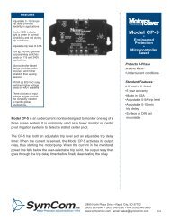
<strong>Model</strong> CP-5The <strong>Model</strong> CP-5is an undercurrent monitor designed to monitor one leg of a 3-phase system.It is commonly used as a tower monitor on center pivot irrigation systems todetect stalled or jammed towers to prevent overwatering.The CP-5 has both an adjustable trip level and an adjustable trip delay timer.When the current is sensed, the <strong>Model</strong> CP-5 activates its output relay, thusstarting the motor/pump.When the current in the monitored power line fallsbelow the user-selectable trip point, the unit goes through a trip delay timerthen deactivates the output relay.See Appendix A, Figure 27 for a typical wiring diagram.Available <strong>Model</strong>s:CP-5-115CP-5-460Features• Adjustable trip level• Adjustable trip delaySpecificationsNominal Input VoltageCP-5-115 • • • • • • • • • • • • • 115VACCP-5-460 • • • • • • • • • • • • • 460VACFrequency • • • • • • • • • • • 50*/60HzOperating PointsTrip Level • • • • • • • • • • • • • 0-5 AmpsTrip Delay • • • • • • • • • • • • 0-10 minutesRestart • • • • • • • • • • • • • • 1 secondOutput Relay (SPDT)Pilot Duty Contact Rating • • 480VA @ 240VAC (115V units)470VA @ 600VAC (460V unit)Weight• • • • • • • • • • • • • • 14 oz.*Note: 50Hz will increase all delay timers by 20%36 www.symcom.com • tel: 605-348-5580 800-843-8848 • fax: 605-348-5685
Alternating RelaysProduct Selection MatrixMODELALT-(xxx)-SALT-(xxx)-S-SWALT-(xxx)-XALT-(xxx)-X-SW50R-400-ALTDuplexManual SwitchAvailable <strong>Model</strong>s:ALT-24-SALT-24-S-SWALT-115-SALT-115-S-SWALT-115-XALT-115-X-SWALT-230-SALT-230-S-SWALT-230-XALT-230-X-SWThe <strong>Model</strong> ALTalternating relays are used to alternate between two loads. The ALT is commonly usedin duplex pumping applications to balance the runtime of both pumps.The <strong>Model</strong> ALT-Sis used in single high-level float applications.When the float switch opens,the alternating relay changes state, forcing the other pump to run the nexttime the float closes.See Appendix A, Figure 40 for a typical wiring diagram.The <strong>Model</strong> ALT-Xhas an internal cross-connected relay and is used in dual high-level floatapplications. These floats are commonly referred to as lead and lag floats.The pumps alternate as in the ALT-S version, but the cross-connected relayconfiguration allows both pumps to run simultaneously when both the lead and lagfloats are closed.These relays are also available with a built-in switch (SW option) that is used tomanually force one of the pumps to run every time the float switch is closed. This ishelpful when a pump has been removed for repair or for test purposes.In the case of the <strong>Model</strong> ALT-X-SW, the switch essentially forces one pump to be thelead pump, while still allowing the second to run when both floats are closed.All <strong>Model</strong> ALT relays have a built-in debounce feature that prevents the relay fromchanging state if the switch or float contact bounces momentarily.See Appendix A, Figure 41 for a typical wiring diagram.SpecificationsSupply Voltage24VAC or 24VDC• • • • • • • • • • • • 20-26VAC or VDC115VAC • • • • • • • • • • • • • • • • • • 95-125VAC230VAC • • • • • • • • • • • • • • • • • • 195-250VACSupply Current • • • • • • • • • • • • 40mAPower Consumption • • • • • • • • 5 Watts (max.)Control Input Impedance (min).)24 • • • • • • • • • • • • • • • • • • • • • • 10kΩ115 • • • • • • • • • • • • • • • • • • • • • 56kΩ230 • • • • • • • • • • • • • • • • • • • • • 100kΩContact Rating • • • • • • • • • • • • 480VA @ 240VACDebounce Time Delay • • • • • • • 0.5 secondMust use <strong>Model</strong> OT08 socket for UL Rating!www.symcom.com • tel: 605-348-5580 800-843-8848 • fax: 605-348-568537
<strong>Model</strong> 50R-400-ALTThe <strong>Model</strong> 50R-400-ALTalternating relays are used to alternate between two loads, most commonly in duplexpumping and compressor applications to balance the runtime of both loads.When used in single float applications, the alternating relay changes state after thefloat switch opens*, forcing the other pump to run the next time the float closes.When used in dual float applications, the alternating relay will allow both pumps torun simultaneously when the lead and lag floats are both closed.Part No. 50R-400-ALTAn adjustment knob provides the option to force one pump to run every time thefloat switch is closed.This is helpful when one pump has been removed for repair orfor test purposes.A built-in debounce feature prevents the alternating relay from changing state if thefloat contact bounces momentarily.See Appendix A, Figure 42 for a typical wiring diagram.* The alternating relay will not switch states while current is flowing. Switching will only occur after current hasbeen sensed, followed by loss of current for the duration of the debounce time delay.Features• Alternates between two loads• Solid-state reliability• Debounce time delay• Compatible with single or dual float applicationsSpecificationsSupply Voltage • • • • • • • • • • • • • • • • 380-480VACSupply Current • • • • • • • • • • • • • • • 40mAControl Input Impedance (min) • • • 1MΩContact Rating • • • • • • • • • • • • • • • 470VA @ 600VACGeneral Purpose Relay Rating • • • • 10ADebounce Time Delay • • • • • • • • • • 1 secondPower Consumption • • • • • • • • • • • 5 Watts (max.)38 www.symcom.com • tel: 605-348-5580 800-843-8848 • fax: 605-348-5685
Intrinsically-Safe RelaysAn Intrinsically-Safe Switch is an isolated UL913 listed device used to interface between hazardous and non-hazardous areas.The inputcircuitry is designed to never supply excessive energy thus greatly reducing the likelihood of a spark. Provides intrinsically-safe circuits inthe following locations: Division I and II, Class I, Groups A, B, C, D; Class II, Groups E, F, G and Class III hazardous locations.Features• Compact design• Finger-safe terminals• DIN rail or surface mountable• LED contact state indicator(s)• Isolated output relayProduct Selection MatrixMODELISS-100ISS-101ISS-102AA-DCSISS-105-ISOISS-105-ISO-FMODELISS-102C-M-LCISS-102CCI-M-MCUL 9131 Channel2 Channel5 ChannelReverse Logic5 Amp General Purpose7 Amp General Purpose8 Amp General PurposeDin Rail MountableSurface MountableOctal BaseOutput Status Lights2 Inputs2 OutputsLatching LogicInverted Logic5 Amp General PurposeDIN Rail MountableSurface Mountable100K Ohm Fixed4.7-100K Ohm AdjustableIsolated RelayMSHA EvaluatedProbe Resistance 10k OhmsProbe Resistance 100k Ohmswww.symcom.com • tel: 605-348-5580 800-843-8848 • fax: 605-348-568539
<strong>Model</strong>s ISS-100/ISS-101The <strong>Model</strong> ISS-100 & ISS-101switches are UL 913 listed as an associated apparatus forinterfacing between hazardous and non-hazardous areas.The ISS-100 must be installed in a non-hazardous area.FeaturesISS-100• Compact design• Finger-safe terminals• DIN rail or surface mountable• LED state indicator• Isolated output relay for PLC or control voltageISS-101• Compact design• LED state indicator• DIN rail or surface mountable via common octal-base package• Pop-in replacement for other manufacturers’ parts• Isolated output relay for PLC or control voltageSpecificationsSupply Voltage • • • • • • • • • • • • 90-120VACRelay Output RatingGeneral Purpose• • • • • • • • • • • • • 8A @120VACPilot Duty • • • • • • • • • • • • • • • • • 180VA @120VAC, C300Relay Contact Life (Electrical) • • • • 100,000 cycles min. @ rated loadRelay Contact Life (Mechanical) • • • 10,000,000 cyclesOperating Temperature • • • • • • -20° to 55°CWeight • • • • • • • • • • • • • • • • • • 8 oz.Power Consumption • • • • • • • • 1.5 Watts (max.)Wire range • • • • • • • • • • • • • • • 12 to 20 AWGRecommended Terminal Torque • 3.5 to 4.5 in.-lbs. (max. 6 in.-lbs.)Provides intrinsically safe circuitsin the following locations:• • • • • Division I and II• • • • • • • • • • • • • • • • • • • • • • • • Class I, Groups A,B,C,D;• • • • • • • • • • • • • • • • • • • • • • • • Class II, Groups E,F,G;• • • • • • • • • • • • • • • • • • • • • • • • and Class IIIEntity Parameters• • • • • • • •V oc = 16.8V Po=Voc*Isc• • • • • • • • • • • • • • • • • • • • • I sc = 1.2mA 4• • • • • • • • • • • • • • • • • • • • • L a = 100mH• • • • • • • • • • • • • • • • • • • • • C a = 0.39uFStandards PassedElectrostatic Discharge (ESD) • • IEC 1000-4-2,Level 3,6kV contact,8kV air.Radio Frequency Immunity (RFI) • IEC 61000-4-2, Level 3, 10V/mFast Transients • • • • • • • • • • • • IEC 61000-4-4, Level 3, 4kV input powerSafety Mark • • • • • • • • • • • • UL 913 Sixth Edition,August 8, 200240 www.symcom.com • tel: 605-348-5580 800-843-8848 • fax: 605-348-5685
<strong>Model</strong> ISS-102The ISS-102<strong>SymCom</strong>’s <strong>Model</strong> ISS-102 two-channel, intrinsically-safe switch is designed formultiple uses including a pump-up/pump-down (latching) controller, alternatingrelay, or two-channel switch. Two LEDs indicate the state of the intrinsically-safeinputs and output relays, and user-selectable options are available including avariable resistance threshold for float inputs.The ISS-102 enclosure is surfacemountable, but is also compatible with DIN rail (35mm).-LC Each input channel is active when the corresponding switch is closed.Whenthe lag input (CH2) is activated, the output closes.Applying latching logic, the outputcontact remains closed until the lead (CH1) and the lag (CH2) inputs aredeactivated. Sensitivity is fixed at 100kOhms with a debounce time delay of 2 seconds.Available <strong>Model</strong>s:ISS-102A-LC (Latching Controller)ISS-102AA-DCS (Dual Channel Switch)ISS-102ACI-MC (Multi-function Controller)ISS-102C-M-LC (MSHA* evaluated)ISS-102CCI-M-MC (MSHA* evaluated)* Mine Safety and Health Administration-DCS This dual-channel switch has a debounce delay feature of 0.5 seconds.Resistance probes or switches can be used on its inputs.Two LEDs illuminate theoutput state of either form A relay. Sensitivity is fixed at 100kOhms with adebounce time delay of 0.5 seconds.-MC By selecting the proper functionality through the dip switches, you candefine a pump-up or pump-down, single or dual channel non-latching switch.Thesensitivity adjustment (4, 4.7k-100kOhms) allows you to define the input impedanceat which the output relays (one form A & one form C) will change state, witha debounce time delay of 0.5 or 2 seconds.Features• Compact design• Finger-safe terminals• DIN rail or surface mountable• LED state indicator• 2 input channelsSpecificationsSupply Voltage • • • • • • • • • • • • 120VACRelay Output RatingGeneral Purpose• • • • • • • • • • • • • 5A @120VACPilot Duty • • • • • • • • • • • • • • • • • 180VA @120VAC, C150Relay Contact Life (Electrical) • • • • 100,000 cycles min. @ rated loadRelay Contact Life (Mechanical) • • • 10,000,000 cyclesDebounce Time • • • • • • • • • • • • 0.5 or 2 secondsOperating Temperature • • • • • • -20° to 55°CWeight • • • • • • • • • • • • • • • • • • 9 oz.Power Consumption • • • • • • • • 2 Watts (max.)Wire range • • • • • • • • • • • • • • • 12 to 20 AWGRecommended Terminal Torque • 3.5 to 4.5 in.-lbs. (max. 6 in.-lbs.)Provides intrinsically safe circuitsin the following locations:• • • • • Division I and II• • • • • • • • • • • • • • • • • • • • • • • • Class I, Groups A,B,C,D;• • • • • • • • • • • • • • • • • • • • • • • • Class II, Groups E,F,G;• • • • • • • • • • • • • • • • • • • • • • • • and Class IIIEntity Parameters • • • • • • • V oc = 16.8V Po=Voc*Isc• • • • • • • • • • • • • • • • • • • • • I sc = 1.2mA 4• • • • • • • • • • • • • • • • • • • • • L a = 100mH• • • • • • • • • • • • • • • • • • • • • C a = 0.39uFStandards PassedElectrostatic Discharge (ESD) • • IEC 1000-4-2,Level 3,6kV contact,8kV air.Radio Frequency Immunity (RFI) • IEC 61000-4-2, Level 3, 10V/mFast Transients • • • • • • • • • • • • IEC 61000-4-4, Level 3, 4kV input powerSafety Mark • • • • • • • • • • • • UL 913(except <strong>Model</strong>s ISS-102C-M-LC & ISS-102CCI-M-MC which have beenevaluated by MSHA)Output Replay Type:ISS-102A-LC• • • • • • • • • • • • One Form AISS-102AA-DCS • • • • • • • • • Two Form AISS-102ACI-MC • • • • • • • • • • One Form A & One isolated Form CISS-102C-M-LC • • • • • • • • • • One Form CISS-102CCI-M-MC • • • • • • • • Two Form C (one isolated)www.symcom.com • tel: 605-348-5580 800-843-8848 • fax: 605-348-568541
<strong>Model</strong> ISS-105The ISS-105 IS Super Cellis a “smart” five-channel intrinsically safe relay and pump controller.The IS Super Cell can be configured for a wide variety ofapplications including alternating or non-alternating duplex, duplexseparate pump stop (SPS), triplex, and quadplex applications. It canbe set up for pump up or pump down applications or can be usedas a five-channel relay.Available <strong>Model</strong>s:ISS-105 (Intrinsically-Safe & Pump Controller)ISS-105-ISO (Intrinsically-Safe Only)ISS-105-ISO-F (Intrinsically-Safe Only with Fast Trip Relays)The IS Super Cell has a long list of features that are needed formultiple pump applications. The IS Super Cell can indicate low, highand out-of-sequence alarms. If an out-of-sequence alarm occurs, theskipped pump(s) will be started as intended. The <strong>Model</strong> ISS-105can be set up to do non-alternating control, alternating control andalternating control with one non-alternating pump.The non-alternating pump is intended for use with an emergency orjockey pump. The IS Super Cell can start an emergency pump onceevery 50 cycles to keep it working freely. Using the built-in DIPswitches, individual pumps can be disabled when taken out ofservice for repair or maintenance.Features• 5 intrinsically safe input channels meetingUL 913 Sixth Edition,August 8, 2002• 4 normally open output relays & 1 SPDT output relay• Field selectable pump control options• Duplex pump control• Duplex SPS (separate pump stop) pump control• Triplex pump control• Quadplex pump control• Out-of-sequence alarm• High and/or low alarm options depending on the numberof pumps and settings• Audible alarm output• Meets IEC EMC standards for Electrical Fast Transients (EFT),Electrostatic Discharge (ESD) and Radio Frequency Immunity (RFI)• DIN rail or surface mountable• User-selectable alternator/non-alternator option• Non-alternating pump option for emergency or jockey applications• Pump disable switches• Adjustable lag pump delay for all pumping modes• Adjustable delay-on-make/break timer in five-channel relay modeSpecificationsSupply Voltage • • • • • • • • • • • • 120VACEntity Parameters• • • • • • • •V oc = 16.8V Po=Voc*IscRelay Output Rating• • • • • • • • • • • • • • • • • • • • • I sc = 1.2mA 4General Purpose• • • • • • • • • • • • • 7A @ 240VACPilot Duty • • • • • • • • • • • • • • • • • 480VA @ 240VAC, B300• • • • • • • • • • • • • • • • • • • • • L a = 100mH• • • • • • • • • • • • • • • • • • • • • C a = 0.39uFRelay Contact Life (Electrical) • • • • 100,000 cycles min. @ rated load Standards PassedRelay Contact Life (Mechanical) • • • 10,000,000 cyclesOperating Temperature • • • • • • -40° to 55°CWeight • • • • • • • • • • • • • • • • • • 1.2 lbs.Power Consumption • • • • • • • • 5 Watts (max.)Wire range • • • • • • • • • • • • • • • 12 to 20 AWGElectrostatic Discharge (ESD) • • IEC 61000-4-2,Level 3,6kV contact,8kV air.Radio Frequency Immunity (RFI) • IEC 61000-4-2, Level 3, 10V/mFast Transients • • • • • • • • • • • • IEC 61000-4-4, Level 3, 4kV input power• • • • • • • • • • • • • • • • • • • • • • • 2kV Inputs/OutputsSafety Mark • • • • • • • • • • • • UL 913 Sixth Edition,August 8, 2002Recommended Terminal Torque • 3.5 to 4.5 in.-lbs. (max. 6 in.-lbs.)Provides intrinsically safe circuitsin the following locations:• • • • • Division I and II• • • • • • • • • • • • • • • • • • • • • • • • Class I, Groups A,B,C,D;• • • • • • • • • • • • • • • • • • • • • • • • Class II, Groups E,F,G;• • • • • • • • • • • • • • • • • • • • • • • • and Class III42 www.symcom.com • tel: 605-348-5580 800-843-8848 • fax: 605-348-5685
Pump ControllersPump Controllers are innovative products for controlling a single pump or multiple pumps. Some models can be used to detect pump sealleaks and motor overheating on submersible pumps. Other models can be used as a five-channel pump controller or five-channel switchto support all popular industry standard multi-pump configurations.Features• UL 508 listed (plug-in types must use and OT08-PC or RB08-PC octalbase socket manufactured by Custom Connector to qualify as UL listed)• DIN rail or surface mountable• Finger-safe terminals• LED status indicatorsProduct Selection Matrixwww.symcom.com • tel: 605-348-5580 800-843-8848 • fax: 605-348-568543
<strong>Model</strong> PC-102The PC-102-DL is a Dual seal-Leak detector.The inputs are used to sense sealfailures on pumps. When water is detected, the associated outputrelay is energized. The input logic may be selected to be direct orinverted using DIP switches on the side of the device.-LT is a seal-Leak and over-Temperature detector.The seal-leak inputis used to sense seal failures on submersible pumps while the temperatureinput is used to detect motor overheating. Both can be configuredto suit the probes of your choice.Both units have two form-C isolated output relays and two LEDs,which illuminate when each associated output relay is energized.Available <strong>Model</strong>s:PC-102CICI-DLPC-102CICI-LTFeatures• Compact design• Finger-safe terminals• DIN rail or surface mountable• Two Form C isolated contacts with LED status indicators• Invertible relay logicSpecificationsSupply Voltage • • • • • • • • • • • • • • • 120VAC nominalFrequency • • • • • • • • • • • • • • • • • • 50/60HzSensitivity • • • • • • • • • • • • • • • • • • 4.7k-100kΩInput Logic• • • • • • • • • • • • • • • • • • Direct or invertedDebounce Time Delay • • • • • • • • • 0.5 or 2 secondsRelay Output Rating (2 Form C isolated)Pilot Duty • • • • • • • • • • • • • • • • • • • 180VA @120VAC, C150General Purpose • • • • • • • • • • • • • • • 5A @240VACDepluggable Connector • • • • • • • • Phoenix Contact-Series MSTB plugsOutput Relay Status Indicators • • • LEDsWeight • • • • • • • • • • • • • • • • • • • • 9 oz.Standards PassedElectrostatic Discharge (ESD) • • IEC 61000-4-2,Level 3,6kV contact,8kV air.Radio Frequency Immunity (RFI) • IEC 61000-4-2, Level 3, 10V/mFast Transients • • • • • • • • • • • • IEC 61000-4-4, Level 3, 4kV input power• • • • • • • • • • • • • • • • • • • • • • • 2kV Inputs/OutputsSafety MarksUL • • • • • • • • • • • • • • • • • • • • • • • • UL 508 (File #E68520)cUL • • • • • • • • • • • • • • • • • • • • • • • C22.2 No. 14Operating Temperature • • • • • • • • -20 to 55 o CWire range • • • • • • • • • • • • • • • • • 12-20 AWG44 www.symcom.com • tel: 605-348-5580 800-843-8848 • fax: 605-348-5685
<strong>Model</strong> PC-105The PC-105is a five-channel pump controller designed to handle multiple pumpapplications.Alternatively, it can operate as a five-channel switch.The PC-105s control functions support all of the popular industry-standardmulti-pump configurations.It can indicate low, high and out-of-sequence alarms and use alternatingand non-alternating pump control.The non-alternating pump canbe used as a jockey pump or emergency pump.Using the built-in DIP switches, individual pumps can be disables whentaken out of service for repair or maintenance.Part No. PC-105Features• Low, high and out-of-sequence alarms• Variable time delay / lag pump delay from 2-255 seconds• Separate pump stops• Duplex, triplex or quadplex pump modes• Pump-up or pump-down functions• External silence, reset and alternation configuration• Five-channel relay configuration• DIN rail or surface mountableSpecificationsSupply Voltage • • • • • • • • • • • • 120VACFrequency • • • • • • • • • • • • • • • • 50*/60HzRelay Output RatingGeneral Purpose• • • • • • • • • • • • • 7A @ 240VACPilot Duty • • • • • • • • • • • • • • • • • 480VA @ 240VAC, B300Operating Temperature • • • • • • -20° to 55°CWeight • • • • • • • • • • • • • • • • • • 1.2 lbs.Power Consumption • • • • • • • • 4 Watts (max.)Wire range • • • • • • • • • • • • • • • 12 to 20 AWGRecommended Terminal Torque • 6 in.-lbs. (max.)Pump In-rush delay • • • • • • • • • 2 secondsStandards PassedElectrostatic Discharge (ESD) • • IEC 61000-4-2,Level 3,6kV contact,8kV air.Radio Frequency Immunity (RFI) • IEC 61000-4-2, Level 3, 10V/mFast Transients • • • • • • • • • • • • IEC 61000-4-4, Level 3, 4kV input power• • • • • • • • • • • • • • • • • • • • • • • 2kV Inputs/OutputsSafety Mark • • • • • • • • • • • • UL 508 (File #E68520)*Note: 50Hz will increase all delay timers by 20%www.symcom.com • tel: 605-348-5580 800-843-8848 • fax: 605-348-568545
<strong>Model</strong> 201-100-SLDThe <strong>Model</strong> 201-100-SLDis a plug-in style seal leak detector to sense seal failures on submersible pumps.Theuse of an OT08-PC or RB08-PC octal socket, manufactured by Custom ConnectorCorp is required to qualify as a UL listed device.Part No. 201-100-SLDFeatures• LED status indicator• Compact plug-in design• DIN rail or surface mountable via octal baseSpecificationsControl Voltage201-100-SLD • • • • • • • • • • • • • • • • • 110/120VAC nominalFrequency • • • • • • • • • • • • • • • • • • 50/60HzSensitivity • • • • • • • • • • • • • • • • • • 4.7k-100kΩOutput contact Rating – SPDTPilot Duty • • • • • • • • • • • • • • • • • • • 480VA @240VACGeneral Purpose • • • • • • • • • • • • • • • 10A @240VACPower Consumption• • • • • • • • • • • 5 Watts (max.)Weight • • • • • • • • • • • • • • • • • • • • 9 oz.Enclosure• • • • • • • • • • • • • • • • • • • PolycarbonateSafety MarksUL • • • • • • • • • • • • • • • • • • • • • • • • UL 508 (File #E68520)CE • • • • • • • • • • • • • • • • • • • • • • • • IEC 60947-6-2Standards PassedElectrostatic Discharge (ESD) • • • • • • • IEC 100-4-2, Level 3, 6kV contact, 8kV airRadio Frequency Immunity, Radiated • • 159 MHz, 10V/mFast Transient Burst • • • • • • • • • • • • • 1000-4-4, Level 3, 3.5kV input power and controlsSurgeIEC• • • • • • • • • • • • • • • • • • • • • • • • IEC 1000-4-5, Level 3, 4kV line-to-line;Level 4, 4kV line-to-groundANSI/IEEE • • • • • • • • • • • • • • • • • • • C62.41 Surge and Ring WaveCompliance to a level of 6kV line-to-lineHi-Potential Test • • • • • • • • • • • • • • • Meets UL 508(2 x rated V + 1000 V for 1 minute)Temperature RangeAmbient Operating • • • • • • • • • • • • • -40° to 70°C (-40° to 158°F)Ambient Storage • • • • • • • • • • • • • • • -40° to 80°C (-40° to 176°F)Relative Humidity • • • • • • • • • • • • 10-95%, non-condensing per IEC 68-2-3Must use <strong>Model</strong> OT08 socket for UL Rating46 www.symcom.com • tel: 605-348-5580 800-843-8848 • fax: 605-348-5685
<strong>Model</strong> 460-15-100-SLDThe <strong>Model</strong> 460-15-100-SLDis a seal leak detector to sense seal failures on submersible pumps.A microcontrollerbasedrelay that monitors the shaft seal of a submersible pump motor. A resistiveprobe is installed in the seal cavity. If water leaks into the pump, the resistancemeasured by the probe decreases.When the resistance drops below the sensitivitysetpoint, the unit will trip and the relay contacts will change state. Output relay logiccan be reversed by removing an external jumper.The unit will automatically resetwhen a fault is cleared.See Appendix A, Figure 39 for typical wiring diagram.Part No. 460-15-100-SLDFeatures• DIN rail or surface mountable• Unique probe protection algorithm• Invertible relay logic• 4.7k to 100kΩ adjustable sensitivity• Microcontroller based• 2 relay contacts• LED status indicatorSpecificationsControl VoltageHi-Potential Test • • • • • • • • • • • • • • • Meets UL508460-15-100-SLD • • • • • • • • • • • • • • • 110/120VAC nominal• • • • • • • • • • • • • • • • • • • • • • • • (2 x rated V + 1000 V for 1 minute)Frequency • • • • • • • • • • • • • • • • • • 50*/60HzEnvironmentalSensitivity • • • • • • • • • • • • • • • • • • 4.7k-100kΩTemperature RangeOutput contact Rating – SPDTAmbient Operating • • • • • • • • • • • • • -40° to 70°C (-40° to 158°F)Pilot Duty • • • • • • • • • • • • • • • • • • • 360VA @ 240VACAmbient Storage • • • • • • • • • • • • • • • -40° to 80°C (-40° to 176°F)General Purpose • • • • • • • • • • • • • • • 8A @ 240VACClass of Protection • • • • • • • • • • • • IP20, NEMA 1 (finger safe)Power Consumption• • • • • • • • • • • 2 Watts (max.)Relative Humidity • • • • • • • • • • • • 10-95%, non-condensing per IEC 68-2-3Weight • • • • • • • • • • • • • • • • • • • • 1 lb. (max.)Enclosure• • • • • • • • • • • • • • • • • • • Polycarbonate*Note: 50Hz will increase all delay timers by 20%TerminalTorque • • • • • • • • • • • • • • • • • • • • • 6 in.-lbs.Wire• • • • • • • • • • • • • • • • • • • • • • • AWG 12-20 AWGSafety MarksUL • • • • • • • • • • • • • • • • • • • • • • • • UL 508 (File # E68520)Standards PassedElectrostatic Discharge (ESD) • • • • • • • IEC 100-4-2, Level 3, 6kV contact, 8kV airRadio Frequency Immunity, Radiated • • 159 MHz, 10 V/mFast Transient Burst IEC • • • • • • • • • • 1000-4-4, Level 3, 3.5kV input power and controlsSurgeIEC• • • • • • • • • • • • • • • • • • • • • • • • IEC 1000-4-5, Level 3, 4kV line-to-line;• • • • • • • • • • • • • • • • • • • • • • • • Level 4, 4kV line-to-groundANSI/IEEE • • • • • • • • • • • • • • • • • • • C62.41 Surge and Ring Wave Compliance• • • • • • • • • • • • • • • • • • • • • • • • to a level of 6kV line-to-linewww.symcom.com • tel: 605-348-5580 800-843-8848 • fax: 605-348-568547
<strong>Model</strong> 460-15-100-LLSThe <strong>Model</strong> 460-15-100-LLSis a liquid level sensor to detect the presence of conductive liquids. A probe ismounted at the desired tank level and connected to the PumpSaver ® .Whenthe probe is submersed, the PumpSaver’s output contacts will change state assoon as the debounce time expires.The adjustable debounce timer is intendedto prevent nuisance actuating due to waves or splashing in the tank.Relay logic can be inverted so the PumpSaver’s output contacts change statewhen the probe is no longer submersed.Part No. 460-15-100-LLSFeatures• DIN rail or surface mountable• Unique probe protection algorithm• Invertible relay logic• Adjustable debounce timer• Microcontroller based• 2 relay contacts• LED status indicatorsSpecificationsControl VoltageHi-Potential Test • • • • • • • • • • • • • • • Meets UL508460-15-100-LLS • • • • • • • • • • • • • • • • 110/120VAC nominal• • • • • • • • • • • • • • • • • • • • • • • • (2 x rated V + 1000 V for 1 minute)Frequency • • • • • • • • • • • • • • • • • • 50*/60HzEnvironmentalSensitivity • • • • • • • • • • • • • • • • • • 100kΩTemperature RangeOutput contact Rating – SPDTAmbient Operating • • • • • • • • • • • • • -40° to 70°C (-40° to 158°F)Pilot Duty • • • • • • • • • • • • • • • • • • • 360VA @ 240VACAmbient Storage • • • • • • • • • • • • • • • -40° to 80°C (-40° to 176°F)General Purpose • • • • • • • • • • • • • • • 8A @ 240VACClass of Protection • • • • • • • • • • • • IP20, NEMA 1 (finger safe)Power Consumption• • • • • • • • • • • 2 Watts (max.)Relative Humidity • • • • • • • • • • • • 10-95%, non-condensing per IEC 68-2-3Weight • • • • • • • • • • • • • • • • • • • • 1 lb. (max.)Enclosure• • • • • • • • • • • • • • • • • • • Polycarbonate*Note: 50Hz will increase all delay timers by 20%TerminalTorque • • • • • • • • • • • • • • • • • • • • • 6 in.-lbs.Wire• • • • • • • • • • • • • • • • • • • • • • • AWG 12-20 AWGSafety MarksUL • • • • • • • • • • • • • • • • • • • • • • • • UL 508 (File # E68520)Standards PassedElectrostatic Discharge (ESD) • • • • • • • IEC 100-4-2, Level 3, 6kV contact, 8kV airRadio Frequency Immunity, Radiated • • 159 MHz, 10 V/mFast Transient Burst IEC • • • • • • • • • • 1000-4-4, Level 3, 3.5kV input power and controlsSurgeIEC• • • • • • • • • • • • • • • • • • • • • • • • IEC 1000-4-5, Level 3, 4kV line-to-line;• • • • • • • • • • • • • • • • • • • • • • • • Level 4, 4kV line-to-groundANSI/IEEE • • • • • • • • • • • • • • • • • • • C62.41 Surge and Ring Wave Compliance• • • • • • • • • • • • • • • • • • • • • • • • to a level of 6kV line-to-line48 www.symcom.com • tel: 605-348-5580 800-843-8848 • fax: 605-348-5685
Three-Phase PumpSaversMore than just an overload relay, three-phase PumpSavers provide protection from underload, current unbalance, rapid cycleand many other programmable parameters.They provide a digital display for setting parameters, monitoring operation anddisplaying fault codes to aid in troubleshooting pump malfunctions.Features• UL, cUL, and CE listed• RS485 Modbus communication• RM-1000 & RM-2000 compatible• Diagnostic display• Manual resetProduct Selection MatrixMODEL<strong>777</strong>-<strong>KW</strong>/<strong>HP</strong><strong>777</strong>-<strong>KW</strong>/<strong>HP</strong>-P<strong>777</strong>-LR-<strong>KW</strong>/<strong>HP</strong><strong>777</strong>-HVR-<strong>KW</strong>/<strong>HP</strong><strong>777</strong>-575-<strong>KW</strong>/<strong>HP</strong><strong>777</strong>-TS<strong>777</strong>-LR-TS<strong>777</strong>-575-TS<strong>777</strong>-AccuPowerLow VoltagePhase LossPhase ReversalVoltage UnbalanceHigh VoltageContact FailureLow Kilowatt Trip PointLow Horse Power Trip PointUnderload/UndercurrentUL Listed Overload/OvercurrentCurrent UnbalanceRapid CyclingDiagnostic Display* Subtrol is a registered trademark of Franklin Electric Co., Inc.Manual ResetRM-1000 ReadyRM-2000 ReadyRM-2000 CBM Plus ReadySubtrol® High Temp Trip*Displays Shaft Output Power4-20 mA Output OptionClass II GFwww.symcom.com • tel: 605-348-5580 800-843-8848 • fax: 605-348-568549
<strong>Model</strong> <strong>777</strong>-<strong>KW</strong>/<strong>HP</strong>The <strong>Model</strong> <strong>777</strong>-<strong>KW</strong>/<strong>HP</strong>has the underload trip based on power. All other products in the <strong>777</strong>family provide an undercurrent trip.The underpower trip feature is desirable anytime the current vs. loadcharacteristic is non-linear or has little change. In general terms, smallermotors and slow speed motors have little change in current over thenormal load range. Larger motors that are running light loads will alsoshow small current changes over the operating load range.Available <strong>Model</strong>s:<strong>777</strong>-<strong>KW</strong>/<strong>HP</strong><strong>777</strong>-<strong>KW</strong>/<strong>HP</strong>-P<strong>777</strong>-LR-<strong>KW</strong>/<strong>HP</strong><strong>777</strong>-HVR-<strong>KW</strong>/<strong>HP</strong><strong>777</strong>-575-<strong>KW</strong>/<strong>HP</strong><strong>KW</strong>/<strong>HP</strong> products should be used with all fractional horsepower motorswhen underload protection is needed, and with most motors under3hp. Also use <strong>KW</strong>/<strong>HP</strong> products when the motor is derated (Ex: Coalbed methane well with a 7.5hp submersible pump on a 10hp motor.)Other typical applications are mixer motors up to 50hp and beyondthat run at less than 1800 rpm, magdrive pumps and can pumps. If indoubt, underpower can be used anytime in place of undercurrent protection.<strong>KW</strong>/<strong>HP</strong> products replaced the <strong>777</strong>-<strong>KW</strong> products, which used kilowattsonly.The <strong>777</strong>-<strong>KW</strong>/<strong>HP</strong> can display kilowatts and horsepower.The <strong>777</strong>-<strong>KW</strong>/<strong>HP</strong> also has a high power trip feature that can be enabled overthe network. The high power trip is needed to protect positive displacementpumps in a restricted flow (dead-head) condition.See Appendix A, Figures 1 & 2 for typical wiring diagrams.Features• Low power protection• High power protection• Overcurrent (overload)• High voltage• Low voltage• Current unbalance• Voltage unbalance• Ground fault• Modbus communication• Built-in 3-digit display for setup &diagnosticsPowerPower is Linear, equalsensitivity at bothlow and highloads.CurrentCurrent is not linear, lowsensitivity for low loadsand high sensitivityfor high loads.No LoadFull Load No Load Full Load50 www.symcom.com • tel: 605-348-5580 800-843-8848 • fax: 605-348-5685
<strong>Model</strong> <strong>777</strong>-<strong>KW</strong>/<strong>HP</strong>SpecificationsElectricalNominal Input Voltage<strong>777</strong>-<strong>KW</strong>/<strong>HP</strong>, <strong>777</strong>-<strong>KW</strong>/<strong>HP</strong>-P• • • • • • • • • • • • • • 190-480VAC (3-phase)<strong>777</strong>-LR-<strong>KW</strong>/<strong>HP</strong>• • • • • • • • • • • • • • • • • • • • • 190-480VAC (3-phase)<strong>777</strong>-HVR-<strong>KW</strong>/<strong>HP</strong> • • • • • • • • • • • • • • • • • • • 380-480VAC (3-phase)<strong>777</strong>-575-<strong>KW</strong>/<strong>HP</strong> • • • • • • • • • • • • • • • • • • • • 500-600VAC (3-phase)Current<strong>777</strong>-<strong>KW</strong>/<strong>HP</strong>, <strong>777</strong>-<strong>KW</strong>/<strong>HP</strong>-P• • • • • • • • • • • • • • 2-800A (external CTs required above 90A)<strong>777</strong>-HVR-<strong>KW</strong>/<strong>HP</strong>, <strong>777</strong>-575-<strong>KW</strong>/<strong>HP</strong>• • • • • • • • • 2-800A (external CTs required above 90A)<strong>777</strong>-LR-<strong>KW</strong>/<strong>HP</strong>• • • • • • • • • • • • • • • • • • • • • 1-9AFrequency • • • • • • • • • • • • • • • • • • • • • • • • • • • 50*/60HzTC- Overcurrent Trip Class • • • • • • • • • • • • • • • • • 5, 10, 15, 20, 30 (J prefix enables jam protection feature)Short Circuit Rating • • • • • • • • • • • • • • • • • • • • • 100kAPower Consumption • • • • • • • • • • • • • • • • • • • • • 10 Watts (max.)Output Contact Rating SPDT (Form C) • • • • • • • • • • Pilot duty rating: 480VA @ 240VAC• • • • • • • • • • • • • • • • • • • • • • • • • • • • General purpose: 10A @ 240VACAccuracyVoltage • • • • • • • • • • • • • • • • • • • • • • • • • • ±1%Current• • • • • • • • • • • • • • • • • • • • • • • • • • ±3% (
<strong>Model</strong> <strong>777</strong>-TSThe <strong>Model</strong> <strong>777</strong>-TSis specifically designed for use with Subtrol ®* equipped Franklin submersiblemotor to detect high motor temperatures. It can be used on any 3-phase motordrawing 2-800 Amps. Applications include conveyor systems, HVACequipment, pumps, saws, grinders and other 3-phase electric motors.See Appendix A, Figures 1 & 2 for typical wiring diagrams.*Subtrol is a registered trademark of Franklin Electric Co., Inc.Features• Power factor measurement• Power measurement• Run-hour meter• Programmable automatic, semiautomaticor manual restart control• 3 separate restart timers for rapid-cycle protection,motor cool down and dry-well recovery• Remote pushbutton reset option• Built-in 3-digit display for setup and diagnostics• Last fault indication on display• Last 4 faults available on network or remote displays• Optional remote displays (RM-1000 and RM-2000)• Modbus communication capabilities• DeviceNet capabilities• Adjustable underload trip delaySpecificationsElectricalNominal Input Voltage<strong>777</strong>-TS, <strong>777</strong>-LR-TS• • • • • • • • • • • 190-480VAC<strong>777</strong>-575-TS • • • • • • • • • • • • • • • 500-600VACFrequency • • • • • • • • • • • • • • • • 50*/60HzMotor Full Load Amp Range<strong>777</strong>-TS, <strong>777</strong>-575-TS • • • • • • • • • • 2-800A (external CTs requiredover 90A)<strong>777</strong>-LR-TS • • • • • • • • • • • • • • • • 1-9ATC- Overcurrent Trip Class • • • • • 5, 10, 15, 20, 30• • • • • • • • • • • • • • • • • • • • (J prefix enables jam protection feature)Short Circuit Rating• • • • • • • • • • 100kAPower Consumption • • • • • • • • • 10 Watts (max.)Output Contact Rating SPDT (Form C)Pilot duty: 480VA @ 240VACGeneral purpose: 10A @ 240VACAccuracyVoltage• • • • • • • • • • • • • • • • • ±1%Current • • • • • • • • • • • • • • • • ±3%(
<strong>Model</strong> <strong>777</strong>-AccuPowerThe <strong>Model</strong> <strong>777</strong>-AccuPoweris a fully-programmable 3-phase motor and pump protection relay. It allowsmotor hp rating, full load amps, efficiency, and power factor to be entered andwill accurately calculate motor output power. Voltage, current and powermeasurements can be displayed as well as fault information and setpoints.The built-in display simplifies troubleshooting and allows the user to easily andprecisely configure setpoints. The <strong>777</strong>-AccuPower can be used with <strong>SymCom</strong>’s4-20mA Output Module to give an analog signal proportional to output power.See Appendix A, Figures 1 & 2 for typical wiring diagrams.Features• Motor output power measurement• 3 separate restart timers for rapid-cycle protection, motor cooldown and dry-well recovery• Built-in 3-digit display for setup and diagnostics• Last fault indication on display• Last 4 faults available on network or remote displays• Optional remote displays (RM-1000 and RM-2000)• Modbus communication capabilities• DeviceNet capabilities• Adjustable underload trip delay (network only)• Power factor measurement (network readable)• Run-hour meter (network readable)Protects 3-Phase motors from:• Loss of any phase (single-phasing)• Phase-reversal• Underload• Overcurrent• Single-phase current• Current unbalance• Contact failure• Rapid cyclingSpecificationsElectricalNominal Input Voltage • • • • • 190-480VAC, (standard)Frequency• • • • • • • • • • • • • 50*/60HzMotor Full Load Amp Range • 2-800A (external CTs requiredover 90A)TC- Overcurrent Trip Class • 5, 10, 15, 20, 30• • • • • • • • • • • • • • • • (J prefix enables jam protection feature)Short Circuit Rating • • • • • • 100kAPower Consumption • • • • • • 10 Watts (max.)Output Contact Rating SPDT (Form C)Pilot duty: 480VA @ 240VACGeneral purpose: 10A @ 240VACAccuracyMeasured Horsepower/KilowattTypical • • • • • • • • • • • • ±3%**Voltage • • • • • • • • • • • • • ±1%Current• • • • • • • • • • • • • ±3%(
Single-Phase PumpSaversOur line of single-phase PumpSavers provide ideal protection from dry-well and dead-head situations, as well as overload, over and undervoltagesand rapid cycling.The 77C family of overload relays provide this same protection and much more with programmable parameters,diagnostic display of fault codes to aid in troubleshooting and remote communication capability.Features• Snap-in installation (Insiders)• Panel mounted (Remaining units)• Use power factor calculation for dry-well trip• DiagnosticsProduct Selection MatrixMODEL77C-<strong>KW</strong>/<strong>HP</strong>77C-LR-<strong>KW</strong>/<strong>HP</strong>111-Insider112-Insider231-Insider-P232-Insider111111-3R-L233-P233-P-3R-L233-1.5-P233-1.5-P-3R-L235235-3R-L233-P-UCTD8233-P-UCTD8-3R-LLow VoltageHigh VoltageContact FailureLinear Trip DelayLow Kilowatt Trip PointLow Horse Power Trip PointUnderload/UndercurrentUL Listed Overload/OvercurrentRapid CyclingDiagnostic DisplayDiagnostic LEDsManual ResetInformer CompatibleRM-1000 ReadyRM-2000 ReadyRM-2000 CBM Plus ReadyNEMA 3R-L EnclosureAdj. Underload Sensitivity8 sec. undercurrent trip delay54 www.symcom.com • tel: 605-348-5580 800-843-8848 • fax: 605-348-5685
77C-<strong>KW</strong>/<strong>HP</strong>The <strong>Model</strong> 77C-<strong>KW</strong>/<strong>HP</strong>has important advantages over current monitors in many protection applications.Anymotor load that has a small or very non-linear change in currentvs.load requires the use of a power monitor for underload,dry run anddead-head protection.The change in power vs. load is more linear for mostmotor loads and is greater in magnitude than the change in current in allmotor loads.This is because power measurements take into account bothpower factor (pf) and current.PowerPower is Linear, equalsensitivity at bothlow and highloads.Available <strong>Model</strong>s:77C-<strong>KW</strong>/<strong>HP</strong>77C-LR-<strong>KW</strong>/<strong>HP</strong>CurrentCurrent is not linear, lowsensitivity for low loadsand high sensitivityfor high loads.Small motors,those under 3 hp and especially fractional horsepower,exhibitsmall changes in current vs. load, but the change in power is large.Whenlarger motors are derated (run below their rated horsepower) the changein current is small vs. load, but again, the change in power is large and linear.Othertypical applications include slower speed mixer or agitator motorsup to 50 hp and beyond.These motors and others that run slower thanaround 3400 rpm usually have small current changes vs. load.Magdrive and can pumps tend to be small horsepower, positive displacement-typepumps.These pumps need the high sensitivity of a power monitorto protect them from dry run using the underpower feature and deadheadconditions using the underpower feature if the motor decouples fromthe pump, and the overpower feature if the motor does not decouple.The built-in UL Listed/CSA approved overload, current unbalance, reversephase, single-phase and other protection features are significant benefitsover similar products.The Modbus communications capability allows thisdevice to be directly integrated with the <strong>SymCom</strong> RM-1000 and RM-2000remote displays or other remote monitoring and control equipment.See Appendix A, Figures 28 & 29 for wiring diagram.No LoadFull Load No Load Full LoadSpecificationsElectricalNominal Input Voltage • • • • • 100-240VAC, (standard)Frequency• • • • • • • • • • • • • 50*/60HzMotor Full Load Amp Range77C-<strong>KW</strong>/<strong>HP</strong> • • • • • • • • • • • 2-800A (external CTs requiredover 90A)77C-LR-<strong>KW</strong>/<strong>HP</strong>• • • • • • • • • 1-9ATC- Overcurrent Trip Class • 5, 10, 15, 20, 30, Lin (linear)• • • • • • • • • • • • • • • • (J prefix enables jam protection feature)Short Circuit Rating • • • • • • 100kAPower Consumption • • • • • • 10 Watts (max.)Output Contact Rating SPDT (Form C)Pilot duty: 480VA @ 240VACGeneral purpose: 10A @ 240VACAccuracyVoltage • • • • • • • • • • • • • ±1%Current• • • • • • • • • • • • • ±3%(Direct, no external CTs)Timing• • • • • • • • • • • • • • 5% ±1 secondRepeatabilityVoltage • • • • • • • • • • • • • ±0.5% of nominal voltageCurrent• • • • • • • • • • • • • ±1% (Direct, no external CTs)Safety MarksUL • • • • • • • • • • • • • • • • UL508, UL1053CE • • • • • • • • • • • • • • • • IEC 60947-1, IEC 60947-5-1*Note: 50Hz will increase all delay timers by 20%.Standards PassedElectrostatic Discharge (ESD)IEC 1000-4-2, Level 3, 6kV contact, 8kV airRadio Frequency Immunity (RFI), ConductedIEC 1000-4-6, Level 3 10V/mRadio Frequency Immunity (RFI), RadiatedIEC 1000-4-3, Level 3 10V/mFast Transient BurstIEC 1000-4-4, Level 3, 3.5 kV input powerSurgeIEC 1000-4-5 Level 3, 2kV line-to-line;Level 4, 4kV line-to-groundANSI/IEEE C62.41 Surge and Ring Wave Complianceto a level of 6kV line-to-lineMechanicalDimensions • • • • • • • • • • • 3.1"H x 5.1"D x 3.9"WWeight• • • • • • • • • • • • • • • 1.2 lbs.Max. conductor size thru <strong>777</strong>..0.65” with insulationEnvironmentalTemperature RangeAmbient Operating: -40° to 70°C (-40° to 158°F)Ambient Storage: -40° to 80°C (-40° to 176°F)Pollution Degree: 3Class of Protection: IP20, NEMA 1Relative Humidity: 10-95%, non-condensing per IEC 68-2-3www.symcom.com • tel: 605-348-5580 800-843-8848 • fax: 605-348-568555
InformerALREADY HAVE AN INFORMER??Informers with the 3-button keypad can be returned for a freeupgrade to include the latest features. Please call 800-843-8848for return authorization.An infrared adapter will be included with all new and updatedInformers.This adapter allows communication with the PumpSaverwithout opening the panel door.The Informeris a handheld diagnostic tool designed for use with single-phase PumpSaver ®models equipped with an infrared LED transmitter.The Informer uses an infrared receiver to access information sent from thePumpSaver ® , which can be helpful for troubleshooting the system. Each<strong>SymCom</strong> single-phase PumpSaver ® model equipped with an infrared LEDtransmits valuable information from the device. To retrieve thisinformation, the Informer's receiver must be directed toward the PumpSaver'sLED transmitter. A green communication status light indicates when theInformer is receiving data from the PumpSaver ® . If communication is lost, theInformer will display the last values it received. The Informer automaticallyturns off after 2 minutes of non-use to conserve battery power.The Informer displays:• Real-time voltage, current, and power• Dry-well and overload trip points• Calibration voltage• Last fault• Voltage, current, and power at last fault• Highest/lowest voltage and current since last calibration• <strong>Model</strong> number• Run timeSpecificationsPowerInput • • • • • • • • • • • • 9 Volts DC (requires one 9-volt alkaline battery)Consumption • • • • • • 0.25 Watt max.Auto Shut-off • • • • • • 2 minutesOperating Temp. • • • • 0 to 60°CCommunicationSignal • • • • • • • • • • • • InfraredRange • • • • • • • • • • • 1-10 ft.Data Update • • • • • • • 2 secondsAccuracyVoltage • • • • • • • • • • ±2%Current • • • • • • • • • • ±2%Power • • • • • • • • • • • ±4%ResolutionVoltage • • • • • • • • • • 1.0VACCurrent • • • • • • • • • • 0.1 Amp ACPower • • • • • • • • • • • 0.01kWDisplay • • • • • • • • • • • Liquid crystalSize • • • • • • • • • • • • • 2 rows x 16 charactersKeypad • • • • • • • • • • • Three 0.5” buttonsMechanical Life • • • • • 500,000 actuationsOverlay Material • • • • LexanEnclosureDimensions • • • • • • • • 5.5” H x 3.6” W x 1.125” DWeight • • • • • • • • • • • 6 oz. (w/out battery)Material • • • • • • • • • • Black ABS56 www.symcom.com • tel: 605-348-5580 800-843-8848 • fax: 605-348-5685
111 & 231-INSIDER-P<strong>Model</strong>s 111-Insider and 231-Insider-Pare made by <strong>SymCom</strong> for Franklin,CentriPro & Pentek control boxes.SpecificationsPart No. 111-InsiderPart No. 231-Insider-P<strong>Model</strong>s 111-Insider and 231-Insider-P are nowcompatible with the Informer handheld diagnostic tool withthe use of the Informer IR kit.The kit attaches to the frontof the PumpSaver ® and allows the infrared signal to be readoutside the control box via a flexible 12-inch light pipe.Thekit is available at a nominal charge. Read more about thecapabilities of the informer on page 56.<strong>Model</strong> 111-InsiderSingle-Phase Line Voltage (±10%) • • 115VACLoad Range• • • • • • • • • • • • • • • • • • 1/3-1/2hpFrequency• • • • • • • • • • • • • • • • • • • 50*/60HzOperating PointsOverload • • • • • • • • • • • • • • • • • • • • 125% of Cal. PointUnderload • • • • • • • • • • • • • • • • • • • Approx. 80% of Cal. PointWith high sensitivity jumper removed • • Approx. 87% of Cal. PointOvervoltage Reset Point • • • • • • • • • • 132.5Undervoltage Reset Point • • • • • • • • • • 95Trip Delay Time (Overload)• • • • • • • • • 5 secondsTrip Delay Time (Dry Well) • • • • • • • • • 4 secondsOperating Temperature • • • • • • • • • • • -40° to 70°C(-40° to 158°F)Restart Delay TimeOvervoltage/Undervoltage Delay • • • • • 2 secondsAll other faults (Dry-Well Rec.Timer) • • 2-225 min., ManualOutput Contact Rating (SPST) • • • • 1/2 hp @ 115VAC• • • • • • • • • • • • • • • • • • • • • • • • • • (17A max.)Weight • • • • • • • • • • • • • • • • • • • • • 10 oz.Power Consumption • • • • • • • • • • • 5 Watts (max.)Safety MarksUL • • • • • • • • • • • • • • • • • • • • • • • • • • • • • •UL 508CSA • • • • • • • • • • • • • • • • • • • • • • • • • • • • •C22.2 No. 14The <strong>Model</strong> 111-Insider & <strong>Model</strong> 231-Insider-Pare designed to protect single-phase pumps from dry-well, dead-head, jammedimpeller, overvoltage, and undervoltage conditions.Typical applications includeresidential water wells, commercial water wells, irrigation wells, and golf coursesystems.The <strong>Model</strong> 231-Insider-P single-phase PumpSaver ® fits inside 1/3, 1/2,3/4, and 1hp 230V control boxes. The <strong>Model</strong> 111-Insider single-phasePumpSaver ® fits inside 1/3 and 1/2hp 115V control boxes.A calibration adjustment allows the Insider to be calibrated to specificpumping applications, thereby reducing the possibility of false or nuisancetripping. A unique microcontroller-based voltage and current-sensing algorithmconstantly monitors the incoming power for fluctuations.When an abnormality,such as loss of load is detected, the PumpSaver ® deactivates its output relaydirectly disconnecting the pump motor. The PumpSaver ® then begins itsuser-selectable restart delay (dry-well recovery) timer.When the timer countsdown to zero or power is removed and reapplied, the PumpSaver ® reactivatesits output relay turning the pump back on.The Insider communicates with ahand-held diagnostics tool called the Informer (sold separately).The Informer displays 15 parameters including calibration points, trip points,running points, and last fault.Note:The use of flow restrictors or unusually high head pressures or low waterconditions at the time of calibration may interfere with the detection of deadheadand dry-run conditions. Contact <strong>SymCom</strong> for information on activatingthe special underload high sensitivity mode built into <strong>Model</strong> 111-Insider, <strong>Model</strong>231-Insider-P, <strong>Model</strong> 111, <strong>Model</strong> 233-P and <strong>Model</strong> 235 PumpSaver ® controllers.See Appendix A, Figures 34 & 35 for typical wiring diagrams.<strong>Model</strong> 231-Insider-PSingle-Phase Line Voltage (±10%) • • • • •230VACLoad Range • • • • • • • • • • • • • • • • • • • •1/3-1hpFrequency • • • • • • • • • • • • • • • • • • • • •50*/60HzOperating PointsOverload • • • • • • • • • • • • • • • • • • • • • •125% of Cal. PointUnderload • • • • • • • • • • • • • • • • • • • • • •AdjustableOvervoltage Reset Point • • • • • • • • • • • • •265Undervoltage Reset Point • • • • • • • • • • • •190Trip Delay Time (Overload) • • • • • • • • • • •5 secondsTrip Delay Time (Dry Well) • • • • • • • • • • •4 secondsOperating Temperature • • • • • • • • • • • -40° to 70°C(-40° to 158°F)Restart Delay TimeOvervoltage/Undervoltage Delay • • • • • • •2 secondsAll other faults (Dry-Well Rec.Timer) • • • •2-225 min., ManualOutput Contact Rating (SPST) • • • • • • •1hp @ 240VAC• • • • • • • • • • • • • • • • • • • • • • • • • • • • •(17A max.)Weight • • • • • • • • • • • • • • • • • • • • • • •10 oz.Power Consumption • • • • • • • • • • • • •5 Watts (max.)Safety MarksUL • • • • • • • • • • • • • • • • • • • • • • • • • • • • • •UL 508CSA • • • • • • • • • • • • • • • • • • • • • • • • • • • • •C22.2 No. 14*Note: 50Hz will increase all delay timers by 20%www.symcom.com • tel: 605-348-5580 800-843-8848 • fax: 605-348-568557
112 & 232-INSIDERThe <strong>Model</strong> 112-Insider & <strong>Model</strong> 232-Insiderare designed to protect single-phase pumps from dry-well, dead-head, jammedimpeller, overvoltage and undervoltage conditions.Typical applications includeresidential water wells, commercial water wells, irrigation wells, and golf coursesystems.The <strong>Model</strong> 232-Insider single-phase PumpSaver ® fits inside 1/3, 1/2,3/4, and 1hp 230V Grundfos control boxes. The <strong>Model</strong> 112-Insider singlephasePumpSaver ® fits inside 1/3 and 1/2hp 115V Grundfos control boxes.<strong>Model</strong>s 112 and 232-Insider are made by<strong>SymCom</strong> for Grundfos control boxes.Part No. 112-InsiderPart No. 232-InsiderA calibration adjustment allows the Insider to be calibrated to specificpumping applications, thereby reducing the possibility of false or nuisancetripping. A unique microcontroller-based voltage and current-sensing circuitconstantly monitors the incoming power for fluctuations, overcurrent, andundercurrent. When an abnormality, such as loss of suction is detected, thePumpSaver ® deactivates its output relay and directly disconnects the pumpmotor. The PumpSaver ® then begins its user-selectable restart delay(dry-well recovery) timer. When the timer counts down to zero or power isremoved and reapplied, the PumpSaver ® reactivates its output relay and turnsthe pump back on. An infrared LED communicates directly with a hand-helddiagnostics tool called the Informer (sold separately).The Informer displays 15parameters including calibration point, trip point, running points, and last fault.See Appendix A, Figure 36 for a typical wiring diagram.Note:The use of flow restrictors, unusually high head pressures, or low waterconditions at the time of calibration may interfere with the detection ofdead-head and dry-run conditions. Contact <strong>SymCom</strong> for information on aproduct to fit these applications.Specifications<strong>Model</strong> 112-InsiderSingle-Phase Line Voltage (±10%)• 115VACLoad Range • • • • • • • • • • • • • • • • 1/3-1/2hpFrequency • • • • • • • • • • • • • • • • • 50*/60HzOperating PointsOverload• • • • • • • • • • • • • • • • • • • 125% of Cal. PointUnderload • • • • • • • • • • • • • • • • • • Approx. 80% of Cal. PointWith high sensitivity jumper removed • Approx. 87% of Cal. PointOvervoltage Reset Point • • • • • • • • • 132.5Undervoltage Reset Point • • • • • • • • 95Trip Delay Time (Overload) • • • • • • • 5 secondsTrip Delay Time (Dry Well) • • • • • • • 4 secondsRestart Delay TimeOvervoltage/Undervoltage Delay • • • 2 secondsAll other faults (Dry-Well Rec.Timer) 2-225 minutes, ManualOutput Contact Rating (SPST)• • • 1/2hp @ 115VAC• • • • • • • • • • • • • • • • • • • • • • • • • (17A max.)Operating Temperature • • • • • • -40° to 70°C(-40° to 158°F)Weight • • • • • • • • • • • • • • • • • • • 10 oz.Power Consumption • • • • • • • • • 5 Watts (max.)Safety MarksUL• • • • • • • • • • • • • • • • • • • • • • • • • UL 508CSA• • • • • • • • • • • • • • • • • • • • • • • • C22.2 No. 14*Note: 50Hz will increase all delay timers by 20%<strong>Model</strong> 232-InsiderSingle-Phase Line Voltage (±10%)• 230VACLoad Range • • • • • • • • • • • • • • • • 1/3-1hpFrequency • • • • • • • • • • • • • • • • • 50*/60HzOperating PointsOverload • • • • • • • • • • • • • • • • • • 125% of Cal. PointUnderload • • • • • • • • • • • • • • • • • • Approx. 80% of Cal. PointWith high sensitivity jumper removed • Approx. 87% of Cal. PointOvervoltage Reset Point• • • • • • • • • 265Undervoltage Reset Point • • • • • • • • 190Trip Delay Time (Overload) • • • • • • • 5 secondsTrip Delay Time (Dry Well) • • • • • • • 4 secondsRestart Delay TimeOvervoltage/Undervoltage Delay • • • 2 secondsAll other faults (Dry-Well Rec.Timer) 2-225 minutes, ManualOutput Contact Rating (SPST) • • • • • 1 hp @ 240VAC• • • • • • • • • • • • • • • • • • • • • • • • • (17A max.)Operating Temperature • • • • • • -40° to 70°C(-40° to 158°F)Weight • • • • • • • • • • • • • • • • • • • 10 oz.Power Consumption • • • • • • • • • 5 Watts (max.)Safety MarksUL• • • • • • • • • • • • • • • • • • • • • • • • • UL 508CSA• • • • • • • • • • • • • • • • • • • • • • • • C22.2 No. 1458 www.symcom.com • tel: 605-348-5580 800-843-8848 • fax: 605-348-5685
<strong>Model</strong>s 233-P & 111The <strong>Model</strong> 233-P and 111 PumpSaversare designed to protect single-phase pumps from dry-well, dead-head, jammedimpeller, overvoltage and undervoltage conditions. The PumpSaver ® <strong>Model</strong>233-P protects 230V, 2 or 3 wire pumps from 1/3-3hp. The PumpSaver ®<strong>Model</strong> 111 protects 115V pumps rated 1/3-1hp.Typical applications includesubmersible pumps, centrifugal pumps, circulating pumps, cooling pumps, environmentalpumps, residential water wells, commercial water wells, irrigationwells, and golf course systems.Available <strong>Model</strong>s:111111-3R-L233-P (Replaces 233)233-P-3R-L (Replaces 233-3R-L)233-1.5-P (Replaces 233-1.5)233-1.5-P-3R-L (Replaces 233-1.5-3R-L)233-P-UCTD8233-P-UCTD8-3R-LA calibration adjustment allows the <strong>Model</strong> 233-P and 111 to be calibrated tospecific pumping applications, thereby reducing the possibility of false ornuisance tripping. A unique microcontroller-based voltage and current-sensingcircuit constantly monitors the incoming power for power fluctuations,overcurrent, and undercurrent.When an abnormality, such as loss of suction,is detected, the PumpSaver ® deactivates its output relay and directlydisconnects the pump motor.The PumpSaver ® then begins its user-selectablerestart delay (dry-well recovery) timer.When the timer counts to zero or poweris removed and reapplied, the PumpSaver reactivates its output relay andturns the pump back on. An infrared LED communicates directly with ahand-held diagnostics tool called the Informer (sold separately).The Informerdisplays 15 parameters including calibration point, trip point, running points,and last fault.See Appendix A, Figure 37 for a typical wiring diagram.Note:The use of flow restrictors, unusually high head pressures or low waterconditions at the time of calibration may interfere with the detection ofdead-head and dry-run conditions. Contact <strong>SymCom</strong> for information onactivating the special underload high sensitivity mode built into<strong>Model</strong> 111-Insider, <strong>Model</strong> 231-Insider-P, <strong>Model</strong> 111, <strong>Model</strong> 233-P and <strong>Model</strong>235 PumpSaver ® controllers.Specifications<strong>Model</strong> 233-PSingle-Phase Line Voltage (±10%) • 230VACLoad Range• • • • • • • • • • • • • • • • • 1/3-3hpFrequency• • • • • • • • • • • • • • • • • • 50*/60HzOperating PointsOverload • • • • • • • • • • • • • • • • • • • 125% of Cal. PointUnderload• • • • • • • • • • • • • • • • • • • AdjustableOvervoltage Reset Point• • • • • • • • • • 265Undervoltage Reset Point • • • • • • • • • 190Trip Delay Time (Overload)• • • • • • • • 5 secondsTrip Delay Time (Dry Well) • • • • • • • • 4 seconds• • • • • • • • • • • • • • • • • • • • • • • • • (8 seconds optional)Restart Delay TimeOvervoltage/Undervoltage Delay • • • • 2 secondsAll other faults (Dry-Well Rec.Timer) • 2-225 minutes, ManualOutput Contact Rating (SPST) • • • 3hp @ 240VAC• • • • • • • • • • • • • • • • • • • • • • • • • (17A max.)Operating Temperature • • • • • • -40° to 70°C(-40° to 158°F)Weight • • • • • • • • • • • • • • • • • • • • 14 oz.Power Consumption • • • • • • • • • • 5 Watts (max.)Safety Marks • • • • • • • • • • • • • • • • UL 508CSA C 22.2 No. 14*Note: 50Hz will increase all delay timers by 20%<strong>Model</strong> 111Single-Phase Line Voltage (±10%) • 115VACLoad Range• • • • • • • • • • • • • • • • • 1/3-1hpFrequency• • • • • • • • • • • • • • • • • • 50*/60HzOperating PointsOverload • • • • • • • • • • • • • • • • • • • 125% of Cal. PointUnderload • • • • • • • • • • • • • • • • • • Approx. 80% of Cal. PointWith high sensitivity jumper removed • Approx. 87% of Cal. PointOvervoltage Reset Point • • • • • • • • • 132.5Undervoltage Reset Point• • • • • • • • • 95Trip Delay Time (Overload) • • • • • • • 5 secondsTrip Delay Time (Dry Well) • • • • • • • • 4 secondsRestart Delay TimeOvervoltage/Undervoltage Delay • • • • 2 secondsAll other faults (Dry-Well Rec.Timer) • 2-225 minutes, ManualOutput Contact Rating (SPST) • • • 1hp @ 115VAC• • • • • • • • • • • • • • • • • • • • • • • • • (17A max.)Operating Temperature • • • • • • -40° to 70°C(-40° to 158°F)Weight • • • • • • • • • • • • • • • • • • • • 14 oz.W/ NEMA 3R enclosure w/ lenses • • • 1.6 lbs.Power Consumption • • • • • • • • • • 5 Watts (max.)Safety Marks • • • • • • • • • • • • • • • • UL 508CSA C 22.2 No. 14www.symcom.com • tel: 605-348-5580 800-843-8848 • fax: 605-348-568559
<strong>Model</strong> 235The <strong>Model</strong> 235PumpSaver ® is designed to protect single-phase pumps from dry-well, dead-head,jammed impeller, overvoltage and undervoltage conditions.The PumpSaver <strong>Model</strong>235 protects 5-15hp 230V pumps. Typical applications include submersiblepumps, centrifugal pumps, circulating pumps, cooling pumps, environmentalpumps, residential water wells, commercial water wells, irrigation wells, and golfcourse systems.A calibration adjustment allows the <strong>Model</strong> 235 to be calibrated to specific pumpingapplications, thereby reducing the possibility of false or nuisance tripping.Available <strong>Model</strong>s:235235-3R-LA unique microcontroller-based voltage and current-sensing circuit constantlymonitors the incoming power for fluctuations causing overcurrent, andundercurrent. When an abnormality, such as loss of suction, is detected, thePumpSaver ® deactivates its output relay and directly disconnects the pump motor.The PumpSaver ® then begins its user-selectable restart delay (dry-well recovery)timer.When the timer counts down to zero or power is removed and reapplied, thePumpSaver ® reactivates its output relay and turns the pump back on.An infrared LED communicates directly with a hand-held diagnostic tool called theInformer (sold separately). The Informer displays 15 parameters includingcalibration point, trip point, running points, and last fault.One current transformer (not included) must be used in conjunctionwith a <strong>Model</strong> 235. (Refer to specifications for proper CT sizing.)See Appendix A, Figure 38 for a typical wiring diagram.Note:The use of flow restrictors or unusually high head pressures or low waterconditions at the time of calibration may interfere with the detection of dead-headand dry-run conditions. Contact <strong>SymCom</strong> for information on activating the specialunderload high sensitivity mode built into the <strong>Model</strong> 111-Insider, <strong>Model</strong> 231-Insider-P, <strong>Model</strong> 111, <strong>Model</strong> 233-P and <strong>Model</strong> 235 PumpSaver ® controllers.SpecificationsSingle-Phase Line Voltage (±10%)• 230VACLoad Range • • • • • • • • • • • • • • • 5-15hpFrequency • • • • • • • • • • • • • • • • 50*/60HzCurrent Transformer Ratio • • • 50:5 (5-7.5hp)• • • • • • • • • • • • • • • • • • • • • • • 75:5 (10hp)• • • • • • • • • • • • • • • • • • • • • • • 100:5 (15hp)Operating PointsOverload• • • • • • • • • • • • • • • • • Approx. 125% of Cal. AmpsUnderload (Dry Well) • • • • • • • • Approx. 80% of Cal. AmpsWith high sensitivity jumper removed • Approx. 87% of Cal. AmpsOvervoltage Trip Point • • • • • • • 265Undervoltage Trip Point • • • • • • 190# of Restarts allowed in a 60 seconds period before lockout(Rapid-Cycle Timer)• • • • • • • • • • • 4Operating Temperature • • • • • • -40° to 70°C(-40° to 158°F)Trip Delay TimeOverload • • • • • • • • • • • • • • • • • 5 secondsDry Well • • • • • • • • • • • • • • • • • • 4 secondsRestart Delay TimeOvervoltage/Undervoltage Delay • • 2 secondsAll other faults(Dry-Well Recovery Timer) • • • • • • 2-225 minutes, ManualOutput Contact Rating (SPST)• 480VA @240VAC1 hp, 240VACWeightw/o NEMA 3R Enclosure • • • • • • • 14 oz.w/ NEMA 3R Enclosure w/ lenses • • 1.6 lbs.Power Consumption • • • • • • • • 5 Watts (max.)*Note: 50Hz will increase all delay timers by 20%60 www.symcom.com • tel: 605-348-5580 800-843-8848 • fax: 605-348-5685
Load Sensors<strong>SymCom</strong>’s load sensors are designed to be adaptable to many different applications.They utilize a CT (current transformer) inside the unitto read the currents of the equipment being monitored.The <strong>Model</strong> LSR-0 is a self-powered unit used as a proof relay.The LSRX and LSRX-C units are also self-powered proof relays with either 0.25” fast-on connectors (LSRX) or depluggable connectors (LSRX-C) for use inOEM equipment.The LS-524 is self powered also, but has a solid-state output relay. It also has a a20-turn put to fine tune trip points.LSR-24, 115 and 230 load sensors use external power to help determine feed rates, tool wear, loss of prime on pumps, mixer viscosityand all types of overload and underload conditions. LSRU load sensors come in many different configurations, such as overcurrent andundercurrent or either overcurrent or undercurrent with variable trip, restart or extended restart delay settings.These units also requirean external source.All LSRU models are 115VAC input power, except the LSRU-24-AL-3, which is 24VAC input power.Features• Surface mountable• 10A relay• Variable trip points (except LSR-0, LSRX, LSRX-C)Product Selection MatrixMODELLSR-0LSR-24LSR-115LSR-230LS-524LSRU-24-AL-2LSRU-24-AL-3LSRU-115-AL-1.5LSRU-115-AL-2LSRU-115-AL-3LSRU-115-FC-1.5LSRU-115-OT-1.5LSRU-115-OT-2LSRU-115-OT-3LSRU-115-OR-1.5LSRU-115-OR-2LSRU-115-UE-2LSRU-115-UT-2LSRU-115-UT-3LSRU-115-UR-2LSRU-115-UR-3LSRU-115-OU-1.5LSRU-115-OU-2LSRU-115-OU-3LSRXLSRX-COvercurrentFixed Undercurent (Proof Relay)Adjustable UndercurrentManual Reset SelectionExtended Restart Delay (Minutes)Variable Trip DelayVariable Trip PointVariable Restart Delay10 Amp RelaySolid-State OutputSelf PoweredAlarm Logic (Latching)Motor Control Logic (Momentary Trip)www.symcom.com • tel: 605-348-5580 800-843-8848 • fax: 605-348-568561
<strong>Model</strong> LSR-OThe <strong>Model</strong> LSR-0is a load sensor intended for use as a proof relay. It is used to verify thatcurrent is flowing as intended. It has a guaranteed 15A pull-in current and2.5A drop-out current. Proof relays are typically used to interlock fans,compressors, motors, heating elements and other devices. The LSR-0 isself-powered, that is, it draws its power from the wire being monitored so it doesnot require separate control power wiring.See Appendix A, Figure 30 for a typical wiring diagram.SpecificationsMax Current Ratings • • • • • • • • • • • 135A continuousTurn-on Threshold • • • • • • • • • • • • • Fixed, 15A (max.)*Turn-off Threshold• • • • • • • • • • • • • 2.5A (min.)Safety Marks • • • • • • • • • • • • • • • • • CSA, CSA-NRTL/CPower • • • • • • • • • • • • • • • • • • • • • • Induced from conductorIsolation • • • • • • • • • • • • • • • • • • • • 600VAC rmsRelay Output Rating • • • • • • • • • • • 480VA @ 240VAC Pilot Duty, 10A General Purpose*Conductors may be looped for smaller motor applications.Caution:This product should not be relied upon solely in life or safety applications.The <strong>Model</strong> LS-524is a self-powered load sensor with a solid-state output. It uses a 20-turnpotentiometer (pot) to adjust the pull-in current from 2-100A.The 20-turn potallows fine tuning of the setpoint. The <strong>Model</strong> LS-524 can also be used as asimple low-cost proof relay for PLCs or other electronic controllers.See Appendix A, Figure 31 for a typical wiring diagram.SpecificationsMax Current Ratings • • • • • • • • • • • • • • • • • • • • 135A continuousSensor Supply Voltage • • • • • • • • • • • • • • • • • • • Induced from monitored conductorSupply Current • • • • • • • • • • • • • • • • • • • • • • • • Induced from monitored conductor• • • • • • • • • • • • • • • • • • • • • • • • • • • • • • • • • • • (minimum conductor current required = 2A)Current Adjustment Range (Typical) • • • • • • • • 2-100ACurrent Adjustment Range (min-max) • • • • • • • 0.5-135AIsolation • • • • • • • • • • • • • • • • • • • • • • • • • • • • • 600VAC rmsTrip Setpoint• • • • • • • • • • • • • • • • • • • • • • • • • • Adjustable to ±1% of rangeSensor Hole Size • • • • • • • • • • • • • • • • • • • • • • • 0.725" diameterSolid-State Contact Rating• • • • • • • • • • • • • • • • 0.5A at 30VAC/DC• • • • • • • • • • • • • • • • • • • • • • • • • • • • • • • • • • • (polarized if using DC, see diagrams)Safety Marks • • • • • • • • • • • • • • • • • • • • • • • • • • CSA, CSA-NRTL/CCaution:This product should not be relied upon solely in life or safety applications.62 www.symcom.com • tel: 605-348-5580 800-843-8848 • fax: 605-348-5685
<strong>Model</strong> LSR-24The <strong>Model</strong> LSR-XXXload sensors use current levels to determine feed rates, tool wear, loss ofprime on pumps, mixer viscosity, and all types of overload and underloadconditions.They may also be used to stage pump motors, chillers, and othermachinery.These devices combine a current transformer (CT) with Form C(SPDT) relay contacts to switch alarm circuits, contactors, or any resistiveor inductive load. One simple screwdriver adjustment will calibrate thesensor for all single-phase or 3-phase applications up to 100hp.See Appendix A, Figure 32 for a typical wiring diagram.Available <strong>Model</strong>s:LSR-24LSR-115LSR-230Features• Fine adjustment with 20-turn pot• Status LEDsSpecificationsControl PowerLSR-24 • • • • • • • • • • • • • • • • • • • • • • • • • • • • 24VACLSR-115 • • • • • • • • • • • • • • • • • • • • • • • • • • • 115VACLSR-230 • • • • • • • • • • • • • • • • • • • • • • • • • • • 230VACMax Current Ratings • • • • • • • • • • • • • • • • • 135A max. continuousIsolation • • • • • • • • • • • • • • • • • • • • • • • • • • 600VAC rmsCurrent Adjustment Range (Typical) • • • • • 2-100ACurrent Adjustment Range (Min-Max) • • • • 0.5-135ATrip Setpoint• • • • • • • • • • • • • • • • • • • • • • • Adjustable to ±1% rangeHole Size • • • • • • • • • • • • • • • • • • • • • • • • • 0.725" diameterSPDT Relay Output• • • • • • • • • • • • • • • • • • 480VA @ 240VAC Pilot Duty, 10A General PurposeSafety Marks • • • • • • • • • • • • • • • • • • • • • • • CSA, CSA-NRTL/CCaution:This product should not be relied upon solely in life or safety applications.www.symcom.com • tel: 605-348-5580 800-843-8848 • fax: 605-348-568563
<strong>Model</strong> LSRUSpecificationsAvailable <strong>Model</strong>s:LSRU-24-AL-2LSRU-24-AL-3LSRU-115-AL-1.5LSRU-115-AL-2LSRU-115-AL-3LSRU-115-FC-1.5LSRU-115-OT-1.5LSRU-115-OT-2LSRU-115-OT-3LSRU-115-OR-1.5LSRU-115-OR-2LSRU-115-UE-2LSRU-115-UT-2LSRU-115-UT-3LSRU-115-UR-2LSRU-115-UR-3LSRU-115-OU-1.5LSRU-115-OU-2LSRU-115-OU-3Control Power • • • • • • • • • 24VAC or 115VACIsolation• • • • • • • • • • • • • 600VAC rmsHole Size • • • • • • • • • • • • 0.725" diameterSafety Marks • • • • • • • • • • CSA, CSA-NRTL/CPower • • • • • • • • • • • • • • 2 WattsMotor Acceleration Time • • • 2 secondsCaution:This product should not be relied upon solely in life or safety applications.The <strong>Model</strong> LSRUis a microcontroller-based family of load sensors. The LSRU family of productsemploy three basic types of control logic: motor control logic, alarm logic andfeed control logic.See Appendix A, Figure 33 for a typical wiring diagram.Motor Control LogicSeveral combinations of functions are available in the LSRU, includingovercurrent and undercurrent or either overcurrent or undercurrent withvariable trip, restart or extended restart delay settings. These versions of theLSRU trip on the respective fault and then automatically reset after the restartdelay expires in preparation for the next motor start. LSRUs do not trip onundercurrent when the load turns off, this is recognized as a normal condition.Alarm LogicThe LSRU simply indicates whether the current is between the setpoints oroutside of the setpoints. This product is best used with a PLC or othercontroller where status indication is desired.Feed ControlThe LSRU-FC is a load monitor intended to control feeder mechanisms in avariety of applications. It stops the feeder when the grinder, chipper, saw, auger,etc. nears overload.When the load is reduced to a preset level, the feeder isrestarted.O - Overcurrent TripU - Undercurrent TripT - Adj.Trip Delay (.5-60 seconds)R - Adj. Restart Delay (.5-300 seconds)E - Adj. Extended Restart Delay (2-300 minutes)1.5 - 0-10Amps2 - 5-25 Amps3 - 25-100 Amps64 www.symcom.com • tel: 605-348-5580 800-843-8848 • fax: 605-348-5685
<strong>Model</strong> LSRXThe <strong>Model</strong> LSRXis an AC current sensor designed to energize the output contact whenever 4.5Amps or greater is present.The LSRX is used commonly as an AC current proofrelay to indicate if a motor is operating. It can also be used to interlock fans,compressors, and motors; to indicate equipment status such as feed rates, toolwear, loss of prime on pumps, mixer viscosity, and all types of current sensingconditions; or to stage pump motors, chillers, or other machinery.This device combines a current transformer (CT), transducer, and highcurrent output relay together to switch alarm circuits, contactors, and mostresistive or inductive loads. The LSRX can perform the function of anauxiliary contact, yet has the advantages of universal applicationand isolation.Available <strong>Model</strong>s:LSRXLSRX-CSpecificationsOperating Current .................................... 5-200A ContinuousMinimum Pull-in Current........................ 4.5A (typical), 5.0A (max)*Power ................................................................ Induced from AC conductorRelay Output Rating.................................. 480VA @ 240VAC, B300.............................................................................. 5A General PurposeElectrical Life ................................................ 1x10 5Mechanical Life ............................................ 1x10 7Maximum Conductor Diameter.......... 0.7 in.Output TerminalsLSRX .................................................................. 0.25” quick-connect fast-onsLSRX-C .............................................................. depluggable screw terminalsWire Size ........................................................ 12-26 AWGTorque Rating.................................................. 4.5 in.-lbs.Output Relay Status Indicator.............. LEDWeight.............................................................. 0.15 lbs.Operating Temperature .......................... -20° to 70°C (-4° to 158° F)*Conductors may be looped for smaller motor applications.www.symcom.com • tel: 605-348-5580 800-843-8848 • fax: 605-348-568565
Auxiliary ProductsThe <strong>Model</strong> T-10-(XXX)on-delay timer is a solid-state electronic device that provides accurate andreliable timing for control circuits up to 460VAC. The T-10 features auser-selectable time delay from 6 seconds to 10 minutes and SPDT outputcontacts. When power is applied to the T-10, it immediately begins its timingcycle. During this time, the indicator LED alternates between red and green, andthe output contacts remain inactive. When the timing cycle is complete, theindicator LED turns solid green, and the output contacts are activated. Theoutput contacts will remain activated until power is removed from the T-10.Available <strong>Model</strong>s:The SPDT contact ratings are 480V @ 240VAC on the 115V and 230Vmodels, and 470VA @ 600VAC on the 460V.T-10-100T-10-200T-10-400(115V)(230V)(460V)Features• 600V control relay on 460V modelSpecifications3-phase line voltageT-10-110 • • • • • • • • • • • • • • • • • 115VACT-10-200 • • • • • • • • • • • • • • • • • 230VACT-10-400 • • • • • • • • • • • • • • • • • 460VACFrequency• • • • • • • • • • • • • • • 50*/60HzTiming Range • • • • • • • • • • • • 6 seconds to 10 minutes(Optional) • • • • • • • • • • • • • • • 2 seconds to 12 seconds(Optional) • • • • • • • • • • • • • • • 2 seconds to 60 minutesRepeat AccuracyFixed Condition • • • • • • • • • • • • ±1%Output Contact Rating (SPDT)Pilot Duty • • • • • • • • • • • • • • • • 480VA @ 240VAC (115 and 230V units)• • • • • • • • • • • • • • • • • • • • • • 470VA @ 600VAC (460V unit)Power Consumption • • • • • • • 5 Watts (max.)Weight • • • • • • • • • • • • • • • • • 0.85 lb.*Note: 50Hz will increase all delay timers by 20%.66 www.symcom.com • tel: 605-348-5580 800-843-8848 • fax: 605-348-5685
Current TransformersCurrent Transformers<strong>SymCom</strong> offers a wide array of current transformers.Voltage class: 600VBIL rating: 10kVAvailable <strong>Model</strong>s:CT-50-D-10CT-75-D-10CT-100-D-10CT-150-D-10CT-200-D-10CT-300-D-10CT-100-D-20CT-200-D-20CT-300-D-20CT-400-D-20CT-500-D-20CT-600-D-20CT-300-D-30CT-600-D-302RL56RL76RLCT-xxx (xxx:5 current ratio)-D/F (D-Donut Style, F-Footed Style)-10/20/30 (10-1.0” window; 20-2.0” window; 30-3.0” window)BRASS TERMINALS WITH MOUNTING FEETAvailable <strong>Model</strong>s:CT-50-F-10CT-75-F-10CT-100-F-10CT-150-F-10CT-200-F-10CT-300-F-10CT-150-F-20CT-200-F-20CT-300-F-20CT-400-F-20CT-500-F-20CT-600-F-20CT-1200-F-20CT-300-F-30CT-400-F-30CT-500-F-30CT-600-F-30CT-800-F-302SFT56SFT76SFTOther styles available. Please call for assistance.www.symcom.com • tel: 605-348-5580 800-843-8848 • fax: 605-348-568567
Auxiliary ProductsEnclosuresPart Numbers: NEMA3R-L 6” x 6” x 4” with lenses to view the PumpSaver ®NEMA3R Steel 6” x 6” x 4” fits all PumpSaver ® models andMotorSaver ® models 102A, 250A, 350, 355 and 455Phase 3If a motor is wired without first matching the phase sequencing of the power line to the motor, there is a50% chance the motor will run backwards and may cause severe damage to the system.The Phase 3 serves as both a line and motor sequence analyzer in one unit. It features audibleand visual indicators and works on 60Hz and 400Hz systems from 200-600VAC.Part Number: Phase IIIElectronic MegohmmeterThe <strong>Model</strong> M-500 is an automatic, portable, battery-powered insulation tester. This unit is specificallydesigned as an inexpensive alternative to costly swing needle megohmmeters.The M-500 measures insulationresistance values of motors, generators and transformers up to 1000 megohms at 500VAC, indicating thecondition of insulation on the zone scale. Its compact design and ease of use makes the M-500 a greatdiagnostic tool for motor rewind shops, electrical maintenance personnel and pump installers.Part Number: M-50068 www.symcom.com • tel: 605-348-5580 800-843-8848 • fax: 605-348-5685
Auxiliary ProductsInformer IR Kit (12” long)can be used with the MotorSaver ® <strong>Model</strong> 455 and PumpSaver ® <strong>Model</strong>s 111-Insider and231-Insider. It simply attaches to the face of the unit to provide remote diagnostics withoutopening the panel.Part Number: Informer IR Kit<strong>777</strong> Manual Remote Reset Kit (24” long)allows the <strong>777</strong> line of MotorSaver ® and PumpSaver ® products to be manually reset without opening thepanel door. Simply connect the 9-pin adapter to the <strong>777</strong> communication port and mount the reset switchin a convenient location.Part Number: <strong>777</strong>-MRSWRB08-PCOctal Socketsfor 8-pin plug-in units.Part Numbers: OT08-PC (surface & DIN rail mountable)RB08-PC (surface mountable)OT08-PCwww.symcom.com • tel: 605-348-5580 800-843-8848 • fax: 605-348-568569
Enclosure DimensionsRM-10004.544"3.619"1.425"0.9"RM-20005.97"(151.51)1.02"(25.98)0.99"(25.15)6.37"(161.67)#6 MOUNTING SCREWSPROVIDEDPANEL(.062" - .100" THICK)70 www.symcom.com • tel: 605-348-5580 800-843-8848 • fax: 605-348-5685
Enclosure Dimensions<strong>777</strong>, 77C, 6010.002" (5.08)AOPTIONAL LOOP HOLESBMAIN CONDUCTOR PASS HOLESC1.200"(30.48)2.650"(67.31)2.280"(57.91)3.050"(77.47)D. 0.650" (16.51)4.700"(119.38)5.050"(128.27)3.100" (78.74)3.600" (91.44)3.850" (97.79)3.600" (91.44)3.850" (97.79)Communication Modules802.0”NC2.100L1190 - 480 VAC50/60 HZRELAYONNRTL/CMODEL 80COMNOCONTACT RATING10 A @ 240 VACREVERSE PHASE RELAY L2L3 P/N - 80 - A 200V 400V2.0”MADE IN USA2.900MOUNTING HOLE FORNO. 8 TO .25" SCREW.50”.790.375”.75”2.000.25”www.symcom.com • tel: 605-348-5580 800-843-8848 • fax: 605-348-568571
Enclosure Dimensions102, 250, 350, 355, 45550R, CP-5, 233, 235, T-102.900"(73.66)2.913"(73.99)2.163"(54.94)4.030" (102.36)4.500" (114.30).375"(9.53)0.150" (3.81)5.250" (133.35)Informer, Informer-MS202, 202-RP, 202-SPFRONT.25" Mounting HoleClearance for1/4 in. screw2.625"5.50”(139.7)2.625"BACKAnti-Rotation HoleUse #6 Pan Head Screw3.6”(91.44)1.000"SIDE1.125”(28.57)1.0"72 www.symcom.com • tel: 605-348-5580 800-843-8848 • fax: 605-348-5685
Enclosure DimensionsALT, 201, ISS-101SIDE460, ISS-100, ISS-102, PC-102FRONT"SIDE3.15"(80.01)"".5"(12.7)BOTTOM""BOTTOM1.75"(44.55)2.350"2.375"(60.331)"www.symcom.com • tel: 605-348-5580 800-843-8848 • fax: 605-348-568573
Enclosure Dimensions520-CP, 520-CSFRONT8.25"(209.55)7.5"(190.50)6.75"(717.45)BOTTOM2.5"(63.50)3.25"(82.55)3.75"(95.25)5.25"(133.35)LSR, LSR-0, LS-524, LSRU3.56"(90.43)1.67"(42.42)1.07"(27.18)2.30"(58.42)3.12"(79.25)74 www.symcom.com • tel: 605-348-5580 800-843-8848 • fax: 605-348-5685
Enclosure DimensionsLSRX.7218.22.5063.41.7845.1.205.1FRONT VIEW2.7068.52.2557.2C L1.1328.6C'BOREFOR #8SCREWTOP VIEWLED STATUSINDICATORISS-105, PC-105.192"(.488 )3.511"(89.179).621"(15.773 )3.750"(89.18 )5.025"(127.365 )2.350"(59.690)www.symcom.com • tel: 605-348-5580 800-843-8848 • fax: 605-348-568575
LOVLOVLOVIND. CONT. EQ.LISTEDIND. CONT. EQ.LISTEDIND. CONT. EQ.LISTEDEEENTNTNTMODE SELECT#RU / ADDRRD3 #RFRD2 UCTDRD1 GFTC RUNCUB LVUC HVOC VUBMULTOVERLOAD RELAYDISPLAY MESSAGERESET/PROGRAM SYMCOM, INC. 800-843-8848DISPLAY / PROGRAMLOVTARAPID CITY, SDGL2-L3L2-L3ECAURBCRENTAppendix ACURRENT TRANSFORMER WIRING DIAGRAM FOR MODEL <strong>777</strong> (80 TO 800 AMPS)A B CCONTACTORSYMCOM RECOMMENDS USINGCTs WITH TERMINALS TO SIMPLIFYINSTALLATION.H1X1H1X1H1X112 - 16 AWGStranded Wire3 0MOTORNote: All CTs must face the same direction and all CTsecondaries must be wired identically, i.e. all X1 terminalsenter the main (round) window and returns to H1 terminalafter exiting the loop conductor window (rectangle).Every CT secondary must make five passes through thecorresponding main conductor window on the model <strong>777</strong>.L1 L2 L3 NO C NCMODEL <strong>777</strong>L3-L1L3-L1L1-L2L1-L2AVGAVGAVGAVG+Figure 1 Figure 2MODEL <strong>777</strong>ADDRESS #1L1 L2 L3 NO C NCA1MODE SELECT#RU / ADDRRD3 #RFRD2 UCTDRD1 GFTC RUNCUB LVUC HVOC VUBMULTMODEL <strong>777</strong>OVERLOAD RELAYDISPLAY / PROGRAMTA GL3-L1L2-L3EL1-L2AVGCAUBAVGR RC+ABSV+RRB1V+ADR01RESET/PROGRAM784XMODEL RS485MS-2WMODESCROLLENTERADDRESSA2B2RS485 MODBUS MASTERDESKTOP OR LAPTOP PC,PLC, DCS, SCADAL1 L2 L3 NO C NCMODE SELECT#RU / ADDRRD3 #RFRD2 UCTDRD1 GFTC RUNCUB LVUC HVOC VUBMULTMODEL <strong>777</strong>ADDRESS #2MODEL <strong>777</strong>OVERLOAD RELAYDISPLAY / PROGRAMTA GL3-L1L2-L3EL1-L2AVGCAUBAVGR RC+ABSV+RRRS485 NETWORK50 FT. MAX.A1B1V+www.symcominc.comADR02NOTE: All networkshielding connectionsare omitted for clarity.784XMODEENTERRESET/PROGRAMMODEL <strong>777</strong>ADDRESS #3L1 L2 L3 NO C NCSCROLLADDRESSA2B2MODE SELECT#RU / ADDRRD3 #RFRD2 UCTDRD1 GFTC RUNCUB LVUC HVOC VUBMULTMODEL <strong>777</strong>OVERLOAD RELAYDISPLAY / PROGRAMTA GL3-L1L2-L3EL1-L2AVGCAUBAVGR RC+ABSV+RRwww.symcominc.comUP TO 99 RM-1000s OR <strong>777</strong>s784XRESET/PROGRAMMODEL RS485MS-2WFigure 376 www.symcom.com • tel: 605-348-5580 800-843-8848 • fax: 605-348-5685
LOVLOVLOVIND. CONT. EQ.LISTEDIND. CONT. EQ.LISTEDIND. CONT. EQ.LISTEDEEENTNTNTAppendix AL1 L2 L3 NO C NCMODE SELECT#RU / ADDRRD3 #RFRD2 UCTDRD1 GFTC RUNCUB LVUC HVOC VUBMULTMODEL <strong>777</strong>ADDRESS #1MODEL <strong>777</strong>OVERLOAD RELAYDISPLAY / PROGRAMTAGL3-L1L2-L3EAVGL1-L2CAURBAVGAVGCR+ABSV+RR115 VACRS485 NETWORK4000 FT. MAX.L1L2A1B1REAL TIMEFAULTHISTORYSETPOINTSETUPRM-2000MODESCROLLRUN/RESETSTOPRUNFAULTA2 ADDRESS #1B2RS485 MODBUS MASTERDESKTOP OR LAPTOP PC,PLC, DCS, SCADA784XCHANGESETUPENTERCOMMSTATUSRESET/PROGRAMMODEL RS485MS-2Wwww.symcominc.com115 VACL1L2RM-2000NOTE: All networkshielding connectionsare omitted for clarity.L1 L2 L3 NO C NCMODE SELECT#RU / ADDRRD3 #RFRD2 UCTDRD1 GFTC RUNCUB LVUC HVOC VUBMULTMODEL <strong>777</strong>ADDRESS #2MODEL <strong>777</strong>OVERLOAD RELAYDISPLAY / PROGRAMTAGL3-L1L2-L3EAVGL1-L2CAURBAVGAVGCR+ABSV+RRA1B1REAL TIMEFAULTHISTORYSETPOINTSETUPCHANGESETUPMODESCROLLRUN/RESETSTOPENTERRUNFAULTCOMMSTATUSA2 ADDRESS #2B2RESET/PROGRAML1 L2 L3 NO C NCMODE SELECT#RU / ADDRRD3 #RFRD2 UCTDRD1 GFTC RUNCUB LVUC HVOC VUBMULTMODEL <strong>777</strong>ADDRESS #3MODEL <strong>777</strong>OVERLOAD RELAYDISPLAY / PROGRAMTAGL3-L1L2-L3EAVGL1-L2CA784XURBAVGAVGCR+MODEL RS485MS-2WABSV+RRwww.symcominc.comADDRESS #3RESET/PROGRAM784XMODEL RS485MS-2WUP TO 99 RM-2000s OR <strong>777</strong>sFigure 4TYPICAL WIRING DIAGRAM FOR 400VACTYPICAL WIRING DIAGRAM FOR 200VACINPUT POWER480 VAC 3-PHASEL1L2L3MAGNETICCONTACTOROLOLOLMOTORINPUT POWER240 VAC 3-PHASEL1L2L3MAGNETICCONTACTOROLOLOLMOTORL1 200 400L2MODEL 80L3OLML1 200 400L2MODEL 80L3OLMCONTROL VOLTAGE240 VAC MAX.STARTMANUALMOFFAUTO PILOT CONTACTCONTROL VOLTAGE240 VAC MAX.STARTMANUALMOFFAUTO PILOT CONTACTFigure 5 Figure 6www.symcom.com • tel: 605-348-5580 800-843-8848 • fax: 605-348-568577
Appendix AL1L2L3MODEL 102MODEL 102Figure 7 Figure 8L1L1ALARM201A-AUL2L2L3L3L1L2L3NORMALLY OPENPUSHBUTTON(201A-AU-MR ONLY)LIGHTHORNFigure 9 Figure 10ALARM201A-AUALARM201A-AUL1L2 L1L1L3 L2L2L3L3NORMALLY OPENPUSHBUTTON(201A-AU-MR ONLY)LIGHTHORNNORMALLY OPENPUSHBUTTON(201A-AU-MR ONLY)LIGHTHORNFigure 11201A-AUFigure 12ALARML1L278 www.symcom.com • tel: 605-348-5580 800-843-8848 • fax: 605-348-5685L3
Appendix ATYPICAL WIRING DIAGRAM FOR MODEL 202 WITHMOTOR CONTROLTYPICAL WIRING DIAGRAM FOR MODEL 202 WITHALARM CIRCUITMOTOROL OL OLMMSTARTSTOPAUTOOFFHANDCONTROLVOLTAGE240 VAC MAX.MOTOROL OL OLALARMPOWER240 VACMAX.ALARMM M MOLM M MNCNOCOMNCNOCOML3L2MS202L3L2MS202L1 L2 L3INPUT POWERL1L1 L2 L3INPUT POWERL1Figure 13 Figure 14MODEL 250MODEL 350Figure 15 Figure 16L1L2MOTORL3L1 L2 L3MODEL 355ALARMVOLTAGELIGHTHORNWARNING SYSTEMFigure 17 Figure 18www.symcom.com • tel: 605-348-5580 800-843-8848 • fax: 605-348-568579
Appendix AFigure 19 Figure 20460-14 460-15Figure 21 Figure 22MS50RFigure 23 Figure 2480 www.symcom.com • tel: 605-348-5580 800-843-8848 • fax: 605-348-5685
Appendix AINPUT POWERL1L2L3MMMOLOLOLMOTORMAG.CT1 CT2 CT3 CTCREMOTE RESETL1L2MODEL520OLCOILFigure 25TYPICAL WIRING DIAGRAM FOR MODEL CP-5STOPHANDOFFSTARTML1L2L3CENTERPIVOTPANELFigure 26AUTOPILOTCT1L1L2CT2MODELCP-5OLsMAG.COILPUMPCONTROLPOWERHANDSTOPOFFSTARTMAUTOFigure 27TYPICAL WIRING DIAGRAM FOR MODEL 77C & 77C-<strong>KW</strong>/<strong>HP</strong>WITH MOTOR CONTROLFigure 28A B CTYPICAL WIRING DIAGRAM FOR MODEL 77C & 77C-<strong>KW</strong>/<strong>HP</strong>WITH EXTERNAL CTFigure 29www.symcom.com • tel: 605-348-5580 800-843-8848 • fax: 605-348-568581
RESETAppendix AORANGEBLUE111/231INSIDERMODEL 231INSIDERwww.symcominc.comSOLID-STATESWITCHBLKREDYELB(MAIN)Y(COMM)R(START) L2 L1Franklin Control BoxPentek Control BoxFigure 34 Figure 35CAPACITORBLKORANGEREDRELAYYELFigure 37YELBLK120 VACL1 L2*Y R B*Note: Move short yellow wire from the 90° terminal on L2 to the 45° terminal on L2.Grundfos Control BoxFigure 3636k20k4.7k53k69k85k100kSENSITIVITYSEAL LEAK DETECTORwww.pumpsaver.com1-800-843-8848PASSFAILPROBE INPUT 1PROBETO PLC OROTHER CONTROLLIGHTFigure 39Figure 38www.symcom.com • tel: 605-348-5580 800-843-8848 • fax: 605-348-568583
Appendix ATYPICAL WIRING DIAGRAM FOR A MODEL ALT-X(CROSS CONNECTED)S1ALTERNATING RELAYF1S22 31 48 57 6F2F1 - F2:1-2A TYPICAL SIZEFOR CONTACTOR COILSL1L2Figure 40PUMP#1F3F4L1L2TYPICAL WIRING DIAGRAM FOR A MODEL 50R-400-ALTMAGNETIC CONTACTORSF3 - F6:SIZE FOR INDIVIDUALPUMP APPLICATIONF5L1INPUT POWERL3L2L1M1OLOLOLPUMP 1PUMP#2F6L2M2OLOLPUMP 2Figure 41OLOPTIONALHIGH LEVELFLOATMAIN FLOATCONTROL INPUT L1 L250R-400-ALTM1OLM2OLFigure 4284 www.symcom.com • tel: 605-348-5580 800-843-8848 • fax: 605-348-5685
Terms and Conditions<strong>SymCom</strong>’s Terms and Conditions of SaleGeneral Remarks: These Terms and Conditions of Sale apply to all sales and deliveries effected by <strong>SymCom</strong>. Any terms orconditions on the part of the purchaser that are contrary to these shall not be binding on <strong>SymCom</strong>, even if they form thebasis of the order.Prices: Subject to change without notice. Minimum order is one hundred dollars ($100.00).Terms: Net 30 days from ship date with approved credit. New customers requesting trade credit must submit a credit applicationprior to an order being placed in production.Handling Fee: A $5.00 handling fee will be assessed on each order.Delivery: Buyer's delivery schedule will be met to the best of <strong>SymCom</strong>'s ability. <strong>SymCom</strong> reserves the right to make partialshipments on any order. <strong>SymCom</strong> is not responsible for shipping errors on behalf of the carrier.Freight: All sales are F.O.B., <strong>SymCom</strong>, Inc., Rapid City, SD. Shipments will be made by the transportation method selectedby the Buyer whenever practical.Warranty: <strong>SymCom</strong> warrants its standard products against defects in material or workmanship for a period of five (5) yearsfrom the date of manufacture. All third-party products are warranted by their manufacturer and are handled as a passthroughwarranty by <strong>SymCom</strong>. All custom and private labeled products are warranted for eighteen (18) months unless otherwisestated in writing. The liability of <strong>SymCom</strong> is limited, at its option, to replace, repair, or credit at the purchase price,for any devices which are returned during the warranty period and which prove to be defective. This warranty constitutes<strong>SymCom</strong>'s sole liability hereunder and is in lieu of any other warranty expressed,implied or statutory,written or oral,includingwithout limitation, any implied warranties of merchantability or fitness for a particular purpose and supersedes any representationsmade by any person which are inconsistent with or expand the terms set forth in this document. No person isauthorized to modify this warranty in any way whatsoever.Limits of Liability: IN NO EVENT, REGARDLESS OF CAUSE, SHALL SYMCOM BE LIABLE FOR (1) PENALTIES ORPENALTY CAUSES OF ANY DESCRIPTION OR (2) FOR CERTIFICATION NOT OTHERWISE SPECIFICALLY PROVID-ED HEREIN AND/OR INDEMNIFICATION OF BUYER TO OTHERS FOR COSTS, DAMAGES OR EXPENSES, EACHARISING OUT OF OR RELATED TO THE PRODUCT OR SERVICES OF ANY ORDER OR (3) FOR ANY DAMAGES,WHETHER GENERAL,SPECIAL,OR FOR NEGLIGENCE,AND EXPRESSLY EXCLUDES DAMAGES RESULTING FROMLOSS OF PROFITS, USE OF PRODUCTS,ANY INCIDENTAL, OR INDIRECT CONSEQUENTIAL DAMAGES EVEN IFADVISED OF THE POSSIBILITY OF SUCH DAMAGES. SYMCOM'S OBLIGATION TO REPAIR, REPLACE OR CREDITTHE PURCHASE PRICE SHALL BE THE LIMIT OF ITS LIABILITY UNDER THIS WARRANTY.Returns: All returns must be authorized by <strong>SymCom</strong> and must have a Return Material Authorization (RMA) number.Issuance of a RMA number does not acknowledge goods as defective or under warranty by the seller. Unauthorized returnswill be refused. Authorized returns must be shipped freight prepaid and are subject to inspection and/or testing prior to disposition.Product built to Buyer's specifications cannot be returned for credit or exchanged under any circumstances. For<strong>SymCom</strong>’s complete RMA terms, please visit our website.Cancellation of Custom or Non-Preferred Products: Buyer may cancel an order upon written notice to <strong>SymCom</strong>'s customerservice department and upon payment of cancellation charges,which shall include all costs,both direct and indirect,incurredand/or committed. <strong>SymCom</strong> agrees to divert completed work and work in progress from a cancelled order to other orderswhenever possible.Cancellation of Preferred Products: Full refund if returned within 30 days of purchase. Unit must be in original packagingand in new condition. An RMA must be issued for any return.Technical information in this catalog is subject to change without notice.© 2008 <strong>SymCom</strong> Inc.
www.<strong>SymCom</strong>.com... your electronic control & protection specialistsDid you know.......<strong>SymCom</strong> has the ability to engineer, manufactureand build custom boards and controllers?2880 North Plaza Drive, Rapid City, SD 57702(800) 843-8848 • (605) 348-5580 • fax: (605) 348-5685email: orders@symcom.com • customerservice@symcom.com