INSTALLATION INSTRUCTIONS - Desa
INSTALLATION INSTRUCTIONS - Desa
INSTALLATION INSTRUCTIONS - Desa
- No tags were found...

You also want an ePaper? Increase the reach of your titles
YUMPU automatically turns print PDFs into web optimized ePapers that Google loves.
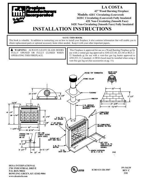
GLOSSARY:WARNING: SAFETY INFORMATION• Do not store or use gasoline or any other flammablevapors or liquids in the vicinity of this or any otherappliance.• Due to high temperatures, the appliance should belocated out of traffic and away from furniture anddraperies.• Do not place clothing or other flammable materials onor near the appliance.• NEVER leave children unattended when a fire isburning in the fireplace.• Improper installation, adjustment, alteration, servicesor maintenance can cause injury, property damage, orloss of life. Refer to this manual for assistance oradditional information. Consult a qualified installer orlocal distributor.• Check local and applicable codes before installing thisfireplace.• This wood burning fireplace complies with the UL127 standard as a FACTORY BUILT FIREPLACEand is listed and tested by UnderwritersLaboratories Inc.• Do not install a fireplace insert in this firebox unlessthe manufacturer’s instructions with the insertspecifically state this firebox has been tested for usewith the insert.• This fireplace is not intended to be used as a substitutefor a furnace to heat an entire home. Use forsupplementary heating only.• This model is not for use in manufactured housing(mobile homes).a) Flush Installations – a type of installation where the frontface of the fireplace is even or leveled with the wall.b) Chase Installation – a type of installation where thechimney is enclosed.c) Perpendicular Side Wall – applies to the minimumclearance between the sidewall and fireplace opening.d) Combustible Material – a type of material that isflammable.e) Nailing Flange – the extended part on both sides of thefireplace face that secures the fireplace.f) Termination – a cap that is placed at the end of thechimney pipe.g) Outside Air Kit – a combustion air inlet that allowscombustion air to enter the firebox area through a duct.h) K-Factor – the thermal conductivity value that is given toa particular material.INTRODUCTION:This fireplace model is a wood burning fireplace intended andapproved for installation in either residential homes orbuildings of standard construction. This fireplace systemrequires the utilization of DESA 8 inch, double-wall, andsnap-lock flue pipe system. Optional glass doors in severalfinishes are available for this fireplace (See Replacement andAccessories parts on page 11).BEFORE YOU BEGIN:Before beginning the installation of your fireplace, read theseinstructions:• All DESA components and fireplaces are safe wheninstalled according to this manual. Use of anycomponents that have not been designed and tested forthis fireplace system may cause a fire hazard.• The DESA warranty will be voided by and DESAdisclaims any responsibility for the following actions:a) Modification of the fireplace, components, doors,chimney system, fans, air inlet system, dampercontrol, etc.b) Use of any component part not manufactured orapproved by DESA in combination with a DESAfireplace system.PROPER <strong>INSTALLATION</strong> is the most important step inensuring safe and continuous operation of this fireplace.SELECTING LOCATION:To determine the safest and most efficient location for yourfireplace, consider the following guidelines:• The location must allow for all proper clearances (seepage 3).• The location should be in a place where the fireplace willnot be affected by drafts such as air condition ducts,windows or doors.• A location that avoids the cutting of joists or roof raftersmakes installation easier.• If an outside air kit is to be installed, accessibility tooutside combustion air must be considered. In somecases, this can be achieved through a vented crawl space.For more details, see section on outside air kit installationon page 4.• If a Fan Kit is to be installed, an electrical supply must beaccessible.• If a gas line is to be installed, consider the location of gassupply.2 For more information, visit www.desatech.com
a Z-type ember protector (not supplied) must be fabricated tofit your required platform height. The ember protector shouldextend under the fireplace a minimum of 1”. The emberprotector should be made of galvanized sheet metal (28 Ga.minimum) to prevent corrosion (see figure 5).STEP 6: Secure fireplace to floor using tie-down straps (seefigure 4) to prevent shifting.Figure 1TYPICAL FIREPLACE LOCATIONSMINIMUM CLEARANCES TO COMBUSTIBLES:• Back and sides of fireplace …………………….. 1” min.Note: The 1” clearance is not required at the nailing flanges• Top spacers …………………………………….. 0” min.• Perpendicular side wall to opening of unit ……. 24” min.• Wall to front of fireplace ……………………… 36” min.• Bottom of fireplace to floor(see step 2 under installing a fireplace) ……….... 0” min.• Mantel clearances ………………………… see page 10• Chimney outer pipe surfaces …………………. 2” min.• Chase inside dimension …………………… 16-1/2” min.Figure 2FRAMING DIMENSIONSWARNING: Do not pack air spaces with insulation orany other material. Do not obstruct fireplace openings (ie.louvers, etc.) with any type of facing material.Combustible material must not be in contact with the backfront face of the fireplace.Figure 3 CORNER FRAMING DIMENSIONSINSTALLING THE FIREPLACE:STEP 1: Frame the opening for the fireplace using thedimensions shown in figures 2 & 3.STEP 2: If the fireplace is to be installed directly on carpeting,tile (other than ceramic), or any combustible material otherthan wood flooring; the fireplace must be installed upon ametal or wood panel extending the full width and depth of thefireplace.STEP 3: Set the fireplace directly in front of this opening andslide the unit back until the nailing flanges touch the sideframing.STEP 4: Check the level of the fireplace and shim with sheetmetal if necessary.STEP 5: Before securing fireplace to prepared framing, theember protector (provided), must be placed between hearthextensions (not supplied), and under the bottom front edge ofthe fireplace to protect against glowing embers fallingthrough. If the fireplace is to be installed on a raised platform,Figure 43 For more information, visit www.desatech.com
HEARTH EXTENSION:A hearth extension is required to protect the combustible floorconstructed in front of the fireplace. The hearth extension isnot included and must be fabricated. The hearth extensionmust project at least 12 inches beyond each side of thefireplace opening (see drawing on front cover).Figure 6AIR KIT <strong>INSTALLATION</strong>CAUTION: AIR DUCTS MUST NOT TERMINATEIN ATTIC SPACE OR GARAGE.Figure 5HEARTH EXTENSIONSThe hearth extension must be made of non-combustible,inorganic material having an effective thermal conductivity“K” of 0.84 BTU IN/FT.HR.F (or less) at 1 inch thick.Thermal conductivity “K” of materials can be obtained fromthe manufacturer of the non-combustible material. Theminimum required thickness for any material could beobtained by the following formula:K factor at 1 inch = thickness required0.84For example, if the material selected has a K factor of 0.25,such as a glass fiber, the following formula would apply:Avoid installing outside air eyebrow in areas where inletopening may be blocked by snow, bushes or other obstacles.It should also be located beyond the reach of children. Themaximum height of air inlet above platform of fireplace is 3 ft.below the termination flue gas outlet.For further details on the installation of the outside air kit,please refer to the instructions included with the air kit. Foroperating instructions please refer to your owner’s manual.The outside air handle is located inside the face opening,above the upper left top of the rear firebrick (see figure 7).Push the rod up to open the air intake and push down to closeit. Always open the mechanism when starting a fire to provideadequate outside combustion air. Close the mechanism whennot in use to prevent cold air from entering the room.0.25 = 0.30 thickness required0.84If the hearth extension is to be covered, use non-combustiblematerial such as tile, slate, brick, concrete, metal, glass,marble, stone etc. Provide a means to prevent the hearthextension from shifting and seal the gap between the fireplaceframe and hearth extension with a non-combustible material(see figure 5).WARNING: HEARTH EXTENSION IS TO BEINSTALLED ONLY AS DESCRIBED.Figure 7AIR KIT DAMPER RODOPTIONAL OUTSIDE AIR KIT (MODEL AK4E):The outside air kit must be installed during the rough framingof the fireplace due to the nature of its location. Outsidecombustion air can be accessed through an exterior wall. Seefigure 6 and Accessories on page 11.GAS LINE <strong>INSTALLATION</strong> (OPTIONAL):Gas line hook up should be done by your supplier or aqualified service person.NOTE: Before you proceed, make sure your gas supply isturned off.4 For more information, visit www.desatech.com
A gas line may be installed for the purpose of installing avented or vent-free gas appliance available through your localdistributor. Use a ½” black iron pipe and appropriate fittings.When installing a gas line, a shut-off valve designed forinstallation outside the appliance is recommended.STEP 1: To install, remove the knockout indentation on thefirebrick wall located approximately 2 inches above therefractory hearth floor on the required side. The knockoutindentation must be firmly tapped with any solid object until itis released. Remove fragmented portions of refractory (seefigure 8).line if desired. Follow the manufacturer’s installationinstructions provided with the gas appliance.CAUTION: All gas piping and connections must betested for leaks after the installation is completed. Afterensuring that the gas valve is on, apply a soap and watersolution to all connections and joints. Bubbles formingshow a leak. Correct all leaks at once. DO NOT USE ANOPEN FLAME FOR LEAK TESTING AND DO NOTOPERATE ANY APPLIANCE IF A LEAK ISDETECTED.VENT-FREE GAS LOG <strong>INSTALLATION</strong>:If you wish to install an unvented gas log set, only unventedgas log sets, which have been found to comply with thestandard for unvented room heaters, ANS Z21.11.2, are to beinstalled in this fireplace.NOTE: A DESA hood must be installed when using anunvented gas log set (see accessories on page 11).Figure 8GAS LINE KNOCKOUTWARNING: Do not operate an unvented gas log set inthis fireplace with the chimney removed.VENTED GAS LOG <strong>INSTALLATION</strong>:STEP 2: Remove gas line cover plate on rear of fireplace andpull out insulation from gas line conduit sleeve. Saveinsulation for reuse.STEP 3: Run a ½” (I.D.) black iron gas line into the fireplacethrough the gas line conduit sleeve (if using a raised platform,add height). Provide sufficient gas line into fireplace chamberfor fitting connection (see figure 9).If you install a decorative gas appliance (vented gas log), thedecorative gas appliance must comply with the Standard forDecorative Gas Appliance for Installation in solid fuel burningfireplace, ANS Z21.60-1996, Z21.84 or RGA 2-72, and shallalso be installed in accordance with the National Fuel GasCode, ANS Z223.1-1996.WARNING: When using a decorative gas appliance,the damper must be removed or permanently locked in thefully opened position.COLD CLIMATE <strong>INSTALLATION</strong>S:The following installation procedures are recommended wheninstalling a fireplace system in a cold climate area. Followingthese steps will aid in reducing cold air infiltration from thefireplace enclosure into living space.Figure 9GAS LINE <strong>INSTALLATION</strong>NOTE: Secure incoming gas line to wood framing to providerigidity for threaded end.STEP 4: Repack insulation around gas line and into sleeveopening. Seal any gaps between gas line and refractoryknockout hole with refractory cement or commercial furnacecement. Install the decorative gas appliance or cap-off gas1. The fireplace must be placed on a solid continuoussurface. You should insulate under the fireplace in allcold climate areas.2. In the case of a raised platform or cantilevered chase, youshould insulate under the structure to reduce airinfiltration.3. Insulate the walls of the chase, both on the outer andinterior partitioning wall (see figure 10). Clearances frompipe to insulating materials must be maintained.4. Using a firestop spacer in the chase at the ceiling level isrecommended for safety and reducing cold air movement(see accessories on page 11).5 For more information, visit www.desatech.com
5. Do not insulate on top of the firebox. The opening in thecollar around the chimney at the top of the fireplace must notbe obstructed (see figure 11).recommended height would be preferable to provide a betterdraw.Maximum height approved for any chimney run with thisfireplace system is 60 feet as measured from the bottom of thefireplace to the flue outlet-end of the termination.ASSEMBLING AND INSTALLING THE DOUBLE WALLCHIMNEY SYSTEMThe DESA chimney system consists of 12, 18, 24, 36 and 48-inch, snap-lock double-wall pipe segments, planned formaximum adaptability to individual site requirements. Actuallengths gained (lineal gain) after fitting overlaps must be takeninto consideration (see figure 12).Figure 10 COLD CLIMATE <strong>INSTALLATION</strong>6. Before finishing the fireplace enclosure, inspect all joints ofthe outer firebox. Seal any gaps of the outer firebox with anon-combustible material. Caulk any gaps between thenailing flange and framing.Figure 12LINEAL GAINFigure 11 FIREPLACE COLLAR OPENINGCHIMNEY SYSTEM:CHIMNEY HEIGHTMinimum chimney height measured from bottom of fireplaceto flue gas outlet-end of the termination is:Straight run16 feetRun with one elbow set16 feetRun with two elbow sets30 feetAn elbow set is consist of one starter elbow and one returnelbow. Uncommon circumstances such as neighboring hills,tall trees, or strong wind areas can cause downdrafts in thechimney system. In such cases, going beyond the minimumEach double wall chimney section consists of a galvanizedouter pipe, a stainless steel inner flue pipe and a wire spacer.The pipe sections must be assembled independently as thechimney is installed. When attaching the chimney directly tothe fireplace, the inner flue pipe section must be installed firstwith the female side up (see figure 12). The outer pipe sectioncan then be installed over the flue pipe section with the maleend up.Press down on each pipe section until the lances securelyengage the hem on the fireplace starter. The wire will assurethe proper spacing between the inner and outer pipe sections(see figure 12).Continue to assemble chimney sections as outlined above,making sure that both the inner and outer pipe sections arelocked together.When installing double wall “snap-lock” chimney together, itis important to insure that the joint between the chimneysections is locked. Check by pulling chimney upward afterlocking. The chimney will not come apart if properly locked.It is not necessary to add screws to keep the chimney together.However, if desired, use screws per directions provided onpage 7, figure 14.6 For more information, visit www.desatech.com
Figure 131 elbow set – 16 to 60 ft. system height, 2 elbow sets – 30 to 60 ft. system height.TYPICAL OFFSET <strong>INSTALLATION</strong>S<strong>INSTRUCTIONS</strong> WHEN OFFSET OF CHIMNEY ISNEEDEDInstalling offset and return elbow (30E-8DM)1. To achieve desired offset, you may installcombination of 12”, 18”, 24”, 36” and 48” length ofdouble wall pipe (see figures 13 and 14).2. The chimney weight above the offset rest on returnelbow. Straps must be securely fastened to rafters orjoists (see figure 15, details A & B).3. Maximum length of pipe between supports (returnelbow or chimney support V12S-8DM) is 6’ ofangled run. Maximum of two (2) 6’ angled runsections per chimney system.All pipe connections betweenthe offset and return must besecured with two screws,only on the outer pipe, andmust not penetrate the innerstainless.OFFSET RISECHIMNEY LENGTHA B 48" 36" 24" 18" 12"4 - 3/8 16 -3/8ELBOW SET ONLY9 - 3/4 25 - 1/2 112 - 3/4 30 - 3/4 115 34 - 3/4 118 40 1 121 - 1/4 46 - 1/4 123 - 3/4 49 - 1/4 1 127 - 3/4 56 - 3/4 130 60 - 3/4 1 133 66 1 136 71 1 138 - 1/4 75 241 - 1/4 80 - 1/4 1 1 145 86 - 3/4 246 - 3/4 89 - 1/2 1 1 151 97 1 153 - 1/4 101 2 156 - 1/4 106 - 1/4 259 - 1/4 111 - 1/2 1 1 161 - 3/4 115 - 1/2 2 164 - 3/4 120 - 3/4 2 168 - 1/4 127 1 270 130 2 1 174 - 1/4 137 - 1/2 1 2 176 - 3/4 141 - 1/2 1 2 179 - 3/4 146 - 3/4 4Figure 15OFFSET PIPE SUPPORTFIRESTOP SPACERS: (FS-8DM)Firestop spacers are required at each point where the chimneypenetrates a floor or ceiling joist space. Their purpose is toestablish and maintain the required clearance between thechimney and the combustible materials.They also provide complete separation from one floor space toanother floor or attic space as required by most codes. Whenthe double wall pipe passes through a framed opening into anattic space, the firestop must be place into the attic floor as infigure 16.When the pipe passes through a framed opening into a livingspace above, the firestop must be placed onto the ceiling frombelow as shown in figure 16.Figure 14OFFSET CHART7 For more information, visit www.desatech.com
PENETRATING THE ROOF:To maintain a 2-inch clearance to the pipe on the roof with apitch, a rectangular opening must be cut.Figure 16FIRESTOP <strong>INSTALLATION</strong>SUPPORT SECTIONS: (12S-8DM)The chimney support section is a 4-strap 12” length of pipe. Achimney support is required at the 30-foot level above thefireplace after a straight chimney run (see figure 17). Thissupport is designed to relieve the extra weight load on thefireplace and elbows when high chimneys are installed.STEP 1: Determine the center point through which the pipewill penetrate the roof.STEP 2: Determine the pitch of the roof. Pitch is the distancethe roof drops over a given span, usually 12 inches. A 6/12pitch means that the roof drops 6 inches for each 12 inchesone measures horizontally down the roof.STEP 3: Use the roof-opening chart (see figure 19) todetermine the correct opening length and flashing required.STEP 4: Remove the shingles around the opening measuredand cut out this section.STEP 5: Add the next sections of the pipe until the endpenetrates the roofline. Check to see that the properclearances are maintained. Extend chimney by adding sectionsof double wall pipe until pipe is a minimum of 30 inchesabove the highest point of the roof cutout. Termination andchimney must extend a minimum of 36 inches above thehighest point where it passes through roof.Figure 17SUPPORT SECTIONSPITCH SLOPE OPENING "A" MAX USE FLASHING(degrees) (inches) MODEL NO.FLAT 0 17 V6F-8DM0 - 6/12 26.6 19 - 1/8 V6F-8DM6/12 - 12/12 45.0 24 - 1/4 V12F-8DMFigure 19ROOF FLASHINGSFigure 18TYPICAL <strong>INSTALLATION</strong>IMPORTANT: If an exposed portion of chimney isgreater than four feet above the roofline, use support wiresto keep the chimney secured. The support wires may beattached to the outer pipe of the chimney with screwsprovided the screws do not penetrate the inner flue pipe.8 For more information, visit www.desatech.com
FLASHING <strong>INSTALLATION</strong>:(V6F-8DM or V6F-8DM)FOLLOW THE <strong>INSTALLATION</strong> <strong>INSTRUCTIONS</strong>PROVIDED WITH THE TERMINATION BEING USED.Determine the flashing to be used with the roof-opening chart.Slide flashing over pipe until base is flat against roof. Replaceas many shingles as needed to cover exposed area and flashingbase. Secure in position by nailing through shingles (seefigure 20). DO NOT NAIL THROUGH FLASHING CONE.Figure 22TERMINATION <strong>INSTALLATION</strong>Figure 20FLASHING <strong>INSTALLATION</strong>STORM COLLAR <strong>INSTALLATION</strong>: (VSC1-8DM)Place storm collar over pipe and slide down until it is snugagainst the open edge of the flashing (see figure 21).CHASE <strong>INSTALLATION</strong>S:Instructions for chase installations are included with the chasestyle termination chosen. In a multiple chase installation, besure to provide adequate distance between terminations toprevent smoke spillage from one termination to another. It isrecommended that terminations be separated at least 24inches, center-to-center, and stacked at vertical heightdifference of 18 inches or more (see figure 23).Figure 21 STORM COLLAR <strong>INSTALLATION</strong>Apply waterproof caulking to all seams and notches aroundstorm collar and also at base around shingles.TERMINATIONS:STANDARD <strong>INSTALLATION</strong>S:The fireplace system must be terminated with the listed roundtop or square chase terminations. The terminations approvedfor this fireplace are RTL-8DM, which can be used forflashing or chase and ETL-8DM for chase style terminationonly. Figure 21 shows an RTL-8DM round top termination.Figure 23 MULTIPLE CHASE TERMINATIONS10-FOOT RULE:All flue gas outlets of chimney terminations must extend aminimum of three feet in height above the highest point whereit passes through the roof and must be at least two feet abovethe highest point of the roof that is within a horizontal distanceof ten feet (see figure 24).9 For more information, visit www.desatech.com
REPLACEMENT PARTS(CONTACT YOUR LOCAL DEALER)ACCESSORY PARTS(CONTACT YOUR LOCAL DEALER)<strong>Desa</strong> International 2701 Industrial Drive, P.O. Box 90024, Bowling Green, KY 42102-9004 www.desatech.com, (800) 323-519011 For more information, visit www.desatech.com