Dayton Portable Oil-Fired Heaters - Desa
Dayton Portable Oil-Fired Heaters - Desa
Dayton Portable Oil-Fired Heaters - Desa

You also want an ePaper? Increase the reach of your titles
YUMPU automatically turns print PDFs into web optimized ePapers that Google loves.
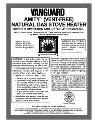
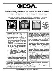
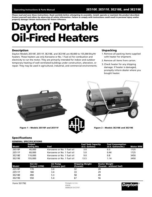
Version B - For ReductionG016.JOperating Instructions & Parts Manual2E510F, 2E511F, 3E218E, and 3E219EPlease read and save these instructions. Read carefully before attempting to assemble, install, operate or maintain the product described.Protect yourself and others by observing all safety information. Failure to comply with instructions could result in personal injury and/orproperty damage! Retain instructions for future reference.<strong>Dayton</strong>®<strong>Portable</strong><strong>Oil</strong>-<strong>Fired</strong> <strong>Heaters</strong>Description<strong>Dayton</strong> Models 2E510F, 2E511F, 3E218E, and 3E219E are 40,000 to 155,000 Btu/Hrheaters. These heaters use only Kerosene or No. 1 fuel oil for combustion andelectricity to run the motor. They are primarily intended for indoor and outdoortemporary heating of well-ventilated buildings under construction, alteration, orrepair. They may be used in agricultural, industrial, and commercial environments.Unpacking1. Remove all packing items suppliedwith heater for shipment.2. Remove all items from carton.3. Check heater for any shippingdamage. If heater is damaged,promptly inform dealer where youbought heater.Figure 1 – Models 2E510F and 2E511FFigure 2 – Models 3E218E and 3E219ESpecificationsGENERAL SPECIFICATIONSOutput Fuel Tank Capacity Fuel ConsumptionModel Rating Btu Fuel (U.S. Gallons) (U.S. Gallons/Hr.) Motor RPM2E510F 40,000 Kerosene or No. 1 fuel oil 3.0 0.3 17252E511F 60,000 Kerosene or No. 1 fuel oil 5.0 0.44 17253E218E 110,000 Kerosene or No. 1 fuel oil 9.0 0.8 34503E219E 155,000 Kerosene or No. 1 fuel oil 13.5 1.14 3450Hot Air Air Pump Shipping Weight Heater WeightModel Output (CFM) Pressure (psi) (Pounds) (Pounds - without fuel)2E510F 170 3.0 32 282E511F 180 3.4 33 293E218E 490 5.3 58 493E219E 550 5.4 67 56®Form 5S1792Printed in U.S.A.034300899/29 5/VCPVP®
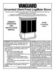
<strong>Dayton</strong> Operating Instructions and Parts Manual®<strong>Dayton</strong> <strong>Portable</strong><strong>Oil</strong>-<strong>Fired</strong> <strong>Heaters</strong>2E510F, 2E511F, 3E218E, and 3E219ESpecifications (Continued)ELECTRICAL SPECIFICATIONSAmperageModel Electrical Input (during normal run)2E510F 120 Volt/60 Hertz 2.02E511F 120 Volt/60 Hertz 2.03E218E 120 Volt/60 Hertz 3.63E219E 120 Volt/60 Hertz 3.6Product IdentificationHot AirOutletHandleUpper ShellFuel TankLowerShellIgnition Control Assembly(on inside of side cover)FuelCapFan GuardAir FilterEnd CoverSide CoverFigure 3 – Models 2E510F and 2E511FPower CordHot Air OutletFuel CapUpper ShellThermostatKnobLower ShellFanGuardSide CoverFuelTankIgnition Control Assembly(on inside of side cover)Figure 4 – Models 3E218E and 3E219EPower Cord1055532
<strong>Dayton</strong> Operating Instructions and Parts ManualModels 2E510F, 2E511F, 3E218E, and 3E219EGeneral Safety InformationMake certain you read and understandall warnings. Keep these instructionsfor reference. They are your guide tosafe and proper operation of thisheater.Safety information appears throughoutthese instructions. Pay closeattention to them. Below are definitionsfor the safety information listedthroughout this manual.Under this heading,installation, operating,and maintenance procedures orpractices will be found that, if notcarefully followed, WILL result in IMME-DIATE serious personal injury or death.Under this heading,installation, operating,and maintenance procedures orpractices will be found that, if notcarefully followed, COULD result insevere personal injury or death.Under this heading,installation, operating,and maintenance procedures orpractices will be found that, if not carefullyfollowed, COULD result in minor personalinjury, product or property damage.IMPORTANT: Every possible circumstancethat might involve a hazard cannot beanticipated. The warnings in this manualand on tags or decals affixed to the unitare therefore not all-inclusive. If aprocedure, work method, or operatingtechnique not specifically recommendedby <strong>Dayton</strong> is used, you must make sure itis safe for you and others. You shouldalso ensure that equipment will not bedamaged or made unsafe by the operatingor maintenance method you choose.105553Carbon monoxidepoisoning may lead todeath! Some people are more affectedby carbon monoxide than others. Earlysigns of carbon monoxide poisoningresemble the flu, with headaches,dizziness, and/or nausea. If you havethese signs, the heater may not beoperating properly, or the areas maynot be sufficiently ventilated. Get freshair at once! Have heater serviced.Improper use of thisheater can causeserious injury or death from burns, fire,explosion, electrical shock, and carbonmonoxide poisoning.Make certain you read and understandall warnings. Keep these instructionsfor reference. They are your guide tosafe and proper operation of thisheater.• Use only Keroseneor No. 1 fuel oil toavoid risk of fire or explosion. Neveruse gasoline, naphtha, paintthinners, alcohol, or other highlyflammable fuels.• Fuelinga) Personnel involved with fuelingshall be qualified and thoroughlyfamiliar with the manufacturer'sinstructions and applicable federal,state, and local regulations regardingthe safe fueling of heating units.b) Only the type of fuel specified onthe heater's data plate shall be used.c) All flame, including the pilotlight, if any, shall be extinguishedand the heater allowed to cool, priorto fueling.3d) During fueling, all fuel lines andfuel-line connections shall beinspected for leaks. Any leaks shallbe repaired prior to returning theheater to service.e) At no time shall more than oneday's supply of heater fuel be storedinside a building in the vicinity ofthe heater. Bulk fuel storage shall beoutside the structure.f) All fuel storage shall be located aminimum of 25 feet from heaters,torches, welding equipment, andsimilar sources of ignition (exception:the fuel reservoir integral withthe heater unit).g) Whenever possible, fuel storageshall be confined to areas wherefloor penetrations do not permit fuelto drip onto or be ignited by a fire atlower elevation.h) Fuel storage shall be in accordancewith the federal, state, orlocal authority having jurisdiction.• Never use heater where gasoline,paint thinner, or other highlyflammable vapors are present.• Follow all local ordinances and codeswhen using heater.• Use only in well-vented areas. Provideat least three square feet of fresh,outside air for each 100,000 Btu/Hr ofrating. This heater produces carbonmonoxide, which is listed by theState of California as a reproductivetoxin under Proposition 65.• Use only in places free of flammablevapors or high dust content.• Use only with the electrical voltageand frequency specified on modelplate.• Use only a three-prong, groundedextension cord.®
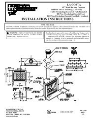
<strong>Dayton</strong> Operating Instructions and Parts Manual®<strong>Dayton</strong> <strong>Portable</strong><strong>Oil</strong>-<strong>Fired</strong> <strong>Heaters</strong>2E510F, 2E511F, 3E218E, and 3E219EGeneral Safety Information(Continued)• <strong>Heaters</strong> used in the vicinity oftarpaulins, canvas, or similarenclosure materials shall be locateda safe distance from such materials.The recommended minimum safedistance is 10 feet. It is furtherrecommended that these enclosurematerials be of a fire retardantnature. These enclosure materialsshall be securely fastened toprevent them from igniting or fromupsetting the heater due to windaction.• Minimum heater clearances fromcombustibles:Outlet: 8 Ft. Sides: 4 Ft.Top: 4 Ft. Rear: 4 Ft.• Locate heater on a stable and levelsurface while hot or running or a firemay occur.• When moving or storing heater, keepheater in a level position or fuelspillage may occur.• Keep children and animals awayfrom heater.• Unplug heater when not in use.• This heater is equipped with thermostat,heater may start anytime.• Never use heater in living or sleepingareas.• Never block air inlet (rear) or airoutlet (front) of heater.• Never move, handle, refuel, orservice a hot, operating, or pluggedinheater.• Never attach duct work to front orrear of heater.• Warning to New York City ResidentsFor Use Only At Construction Sites inaccordance with applicable NYC codesunder NYCFD certificate of approval#4803, #4899, #4908, #4909, or #4934.Theory of OperationTHE FUEL SYSTEMThe air pump forces air through theair line. The air is then pushedthrough the burner head nozzle. Thisair causes fuel to lift from the tank. Afine mist of fuel is sprayed into thecombustion chamber.THE AIR SYSTEMThe motor turns the fan. The fanpushes air into and around thecombustion chamber. This air is heatedand provides a stream of clean, hot air.THE IGNITION SYSTEMThe ignition control assembly providespower to the ignitor. This ignites thefuel/air mixture in the combustionchamber.THE FLAME-OUT CONTROL SYSTEMThis system causes the heater to shutdown if the flame goes out.CleanHeatedAir OutFuelTankCombustion ChamberIgnitorNozzleAir For FuelSystemFuelFilterFigure 5 - Cross Section Operational ViewFuelsUse only Keroseneor No. 1 fuel oil toavoid risk of fire or explosion. Neveruse gasoline, naphtha, paint thinners,alcohol, or other highly flammablefuels.Do not use heavy fuels such as No. 2fuel oil or No. 2 Diesel. Using heavyfuels will result in:• clogged fuel filter and nozzle• carbon buildup on spark plug• the need of nontoxic anti-icer infuel during very cold weatherIMPORTANT: Use a KEROSENE ONLYcontainer. Be sure storage container isclean. Foreign matter such as rust, dirt, orwater will cause the flame-out control toshut down heater. Foreign matter may alsorequire you to clean fuel system often.MotorAir LineTo BurnerAir For Combustionand HeatingFanAir PumpAir IntakeFilterIgnition ControlAssemblyFuelCoolAir InAirOutputFilter1055534
<strong>Dayton</strong> Operating Instructions and Parts ManualModels 2E510F, 2E511F, 3E218E, and 3E219EAssembly(For Models 3E218E and 3E219E Only)These models are furnished withwheels and handles. Wheels, handles,and the mounting hardware are foundin the shipping carton.TOOLS NEEDED• Medium Phillips Screwdriver• 3/8" Open or Adjustable Wrench• Hammer1. Slide axle through wheel supportframe. Install wheels on axle.Hot AirOutletFuelTankFlangeCap NutFigure 6 - Wheel and Handle Assembly,Models 3E218E and 3E219E Only105553Front HandleScrewWheel SupportFrameNutAxleWheelRear HandleAirInletExtendedHubIMPORTANT: When installing wheels,point extended hub of wheels towardwheel support frame (See Figure 6).2. Place cap nuts on axle ends. Gentlytap with hammer to secure.3. Place heater on wheel supportframe. Make sure air inlet end (rear)of heater is over wheels. Line upholes on fuel tank flange with holeson wheel support frame.4. Place handles on top of fuel tankflange. Insert screws throughhandles, fuel tank flange, and wheelsupport frame. Attach nut finger tightafter inserting each screw.5. After inserting all screws, tightennuts firmly.VentilationFollow the minimumfresh, outsideair ventilation requirements. If properfresh, outside air ventilation is notprovided, carbon monoxide poisoningcan occur. Provide proper fresh,outside air ventilation before runningheater.Provide a fresh air opening of at leastthree square feet for each 100,000Btu/Hr rating. Provide extra fresh air ifmore heaters are being used.Example: A 155,000 Btu/Hr heaterrequires one of the following:• a two-car garage door (16-foot-wideopening) raised 3.5 inches• a single-car garage door (9-footwideopening) raised 6.5 inches• two, 30-inch windows raised 11.5inchesOperationReview andunderstand thewarnings in the General SafetyInformation section. They are neededto safely operate this heater. Followall local codes when using this heater.5TO START HEATER1. Follow all ventilation and safetyinformation.2. Locate heater to provide maximumcirculation of the heated air. Followall location requirements noted inGeneral Safety Information, page 3.3. Fill fuel tank with Kerosene or No. 1fuel oil.4. Attach fuel cap.5. If equipped, turn thermostat knobclockwise to the HIGH position.6. Plug power cord of heater intothree-prong, grounded extensioncord. Extension cord must be at leastsix feet long.EXTENSION CORD WIRE SIZEREQUIREMENTS• 6 to 10 feet long, use 18 AWGrated cord.• 11 to 100 feet long, use 16 AWGrated cord.• 101 to 200 feet long, use 14 AWGrated cord.7. Plug extension cord into standard120 Volt/60 hertz, three-hole,grounded outlet.NOTE: Ignitor will preheat for fiveseconds, then heater will start.8. If equipped, adjust thermostat knobto the desired setting.NOTE: If equipped, a cold heater mayaffect the thermostat setting. Furtheradjustments may be needed until theheater cycles at the desired setting.This thermostat is a general-heatingcontrol. It is not intended for precisetemperature control.TO STOP HEATERUnplug extension cord from outlet.TO RESET HEATER1. Unplug extension cord from outletand wait 10 seconds (two minutes ifheater has been running).2. Repeat steps under To Start Heater.®
<strong>Dayton</strong> Operating Instructions and Parts Manual®<strong>Dayton</strong> <strong>Portable</strong><strong>Oil</strong>-<strong>Fired</strong> <strong>Heaters</strong>2E510F, 2E511F, 3E218E, and 3E219EMaintenanceNever serviceheater while it isplugged in, operating, or hot. Severeburns and electrical shock can occur.UPPER SHELL REMOVAL1. Remove screws along each side ofheater using 5/16" nut-driver. Thesescrews attach upper and lower shellstogether (See Figures 7 and 8).2. Lift upper shell off.3. Remove fan guard.Upper ShellFan GuardFigure 7 - Upper Shell Removal, Models2E510F and 2E511FUpperShellFANIMPORTANT: Remove fan from motorshaft before removing motor fromheater. The weight of the motorresting on the fan could damage thefan pitch.1. Remove upper shell (see Figures 7and 8).2. Use 1/8" Allen wrench to loosensetscrew which holds fan to motorshaft.3. Slip fan off motor shaft.4. Clean fan using a soft cloth moistenedwith Kerosene or solvent.5. Dry fan thoroughly.6. Replace fan on motor shaft. Placefan hub flush with end of motorshaft (See Figure 9).7. Place setscrew on flat of shaft. Tightensetscrew firmly (40-50 inch-pounds).8. Replace fan guard and upper shell.FanMotorSetscrewFlushAIR OUTPUT, AIR INTAKE, AND LINTFILTERS1. Remove upper shell (See Figures 7and 8).2. Remove filter end cover screws using5/16" nut-driver (See Figures 10 and 11).3. Remove filter end cover.4. Replace air output and lint filters.5. Wash and dry with soap and wateror replace air intake filter.6. Replace filter end cover.7. Replace fan guard and upper shell.IMPORTANT: Do not oil filters.Lint FilterAir Output FilterAir Intake FilterFilter End CoverFan GuardFigure 10 - Air Output, Air Intake, andLint Filters, Models 2E510F and 2E511FAir Intake FilterFilter End CoverMotorShaftFanGuardFigure 8 - Upper Shell Removal, Models3E218E and 3E219EFigure 9 - Fan Cross SectionLintFilterAir OutputFilterFan GuardFigure 11 - Air Output, Air Intake, andLint Filters, Models 3E218E and 3E219E1055536
<strong>Dayton</strong> Operating Instructions and Parts ManualModels 2E510F, 2E511F, 3E218E, and 3E219EMaintenance (Continued)PUMP PRESSURE ADJUSTMENT1. Remove pressure gauge plug fromfilter end cover (See Figure 12).2. Install accessory pressure gauge (PartNumber HA1180) (See Figure 13).3. Start heater (See Operation, page 5).Allow motor to reach full speed.4. Adjust pressure. Turn relief valve toright to increase pressure. Turn reliefvalve to left to decrease pressure.See specification chart below forcorrect pressure for each model.Model2E510F2E511F3E218E3E219EPumpPressure3.0 psi3.4 psi5.3 psi5.4 psi5. Remove pressure gauge. Replacepressure gauge plug in filter end cover.PressureGauge PlugReliefValveFigure 12 - Pressure Gauge PlugRemovalPressureGaugePRESSURE ADJUSTFigure 13 - Adjusting Pump PressureFUEL FILTER1. Remove side cover screws using5/16" nut-driver.2. Remove side cover.3. Pull upper fuel line off fuel filterneck (See Figure 14).4. Carefully pry bushing, fuel filter, andlower fuel line (Models 3E218E and3E219E only) out of fuel tank (SeeFigure 15).5. Wash fuel filter with clean fuel andreplace in tank.6. Attach upper fuel line to fuel filterneck.7. Replace side cover.PSideCoverFuel FilterUpper Fuel LineFigure 14 - Fuel Filter Removal, Models2E510F and 2E511FFuel Filter, Bushing, andLower Fuel LineSideCoverUpperFuelLineFigure 15 - Fuel Filter Removal, Models3E218E and 3E219E1055537®
<strong>Dayton</strong> Operating Instructions and Parts Manual®<strong>Dayton</strong> <strong>Portable</strong><strong>Oil</strong>-<strong>Fired</strong> <strong>Heaters</strong>2E510F, 2E511F, 3E218E, and 3E219EMaintenance (Continued)IGNITOR1. Remove upper shell and fan guard(See page 6).2. Remove fan (See page 6).3. Remove 4 side cover screws with a5/16" nut driver. Remove side cover(See Figures 14 and 15).4. Disconnect ignitor wires (yellow for3E218E and 3E219E, gray for2E510F and 2E511F) from ignitioncontrol assembly (See Figure 16).Pull the ignitor wires up throughthe hole in the lower shell.5. Disconnect fuel line hose and airline hose. Remove photocell fromphotocell bracket (See Figure 16).CombustionChamberAirLineHoseFuelLineHosePhotocellBracketPhotocellAssemblySide CoverNozzleAdapterBracketIgnitorIgnitorWiresIgnitionControlAssemblyFigure 16 - Disconnecting Ignitor Wiresfrom Ignition Control Assembly6. Remove combustion chamber.Stand combustion chamber on endwith nozzle adapter bracket on top(See Figure 17).Ignitor Screw/WasherAssemblyPhotocellBracketCombustionChamberIgnitorElementNozzle AdapterBracket OpeningFigure 17 - Ignitor ReplacementIgnitorNozzleAdapterBracket7. Remove ignitor screw with a 1/4"nut driver. Carefully remove ignitorfrom nozzle adapter bracket.Do not bend orstrike ignitorelement. Handle with care.8. Carefully remove replacementignitor from styrofoam packing.9. Carefully guide ignitor intoopening in nozzle adapter bracket.Do not strike ignitor element.Attach ignitor to nozzle adapterbracket with screw using a 1/4" nutdriver (See Figure 17). Torque 8 to15 in. lbs. Do not over torque.10. Replace combustion chamber.11. Route the ignitor wires back downthrough the hole in the lower shell.Connect wires to the ignitioncontrol assembly.12. Replace side cover (See Figures 14and 15).13. Connect and route fuel line hoseand air line hose to nozzle adapterassembly (see Fuel and Air LineReplacement and Proper Routing,page 9).14. Replace photocell in photocellbracket. Route wires as shown inFigure 18, 19, or 20.15. Replace fan (See page 6).16. Replace fan guard and upper shell(See page 6).CombustionChamberBurnerStrapPhotocellBracketAir LineHoseNozzle/AdapterAssemblyFuel LineHoseFigure 18 - Removing Air and Fuel LineHoses (40 and 60,000 Btu/Hr Models Only)CombustionChamberBurnerStrapPhotocellBracketAir LineHoseFuel LineHoseFigure 19 - Removing Air and Fuel LineHoses (110,000 Btu/Hr Model Only)Nozzle/AdapterAssembly1055538
<strong>Dayton</strong> Operating Instructions and Parts ManualModels 2E510F, 2E511F, 3E218E, and 3E219EMaintenance (Continued)Air LineHoseFigure 20 - Removing Air and Fuel LineHoses (155,000 Btu/Hr Model Only)NOZZLE1. Remove upper shell (See page 6).2. Remove fan (See page 6).3. Remove fuel and air line hoses fromnozzle assembly (See Figure 18, 19,or 20).4. Turn nozzle assembly 1/4 turn toleft and pull toward motor toremove (See Figure 21).105553CombustionChamberBurnerStrapPhotocellBracketBurner StrapNozzle/AdapterAssemblyFuel LineHoseNozzleAssemblyFigure 21 - Removing Nozzle Assembly,All Models5. Place plastic hex-body into vise andlightly tighten.6. Carefully remove nozzle from thenozzle adapter using 5/8" socketwrench.NozzleFaceNozzleNozzleSleeveNozzle AdapterAir LineFitting7. Blow compressed air through faceof nozzle. This will free any dirt innozzle area.8. Inspect nozzle sleeve for damage.9. Replace nozzle into nozzle adapteruntil nozzle seats. Tighten 1/3 turnmore using 5/8" socket wrench (40-45 inch-pounds).10. Attach nozzle assembly to burnerstrap.11. Attach fuel and airline hoses tonozzle adapter assembly (see Fueland Air Line Replacement andProper Routing).12. Replace fan (See page 6).13. Replace fan guard and upper shell.9Fuel LineFittingFigure 22 - Nozzle and Nozzle Adapter,All ModelsFUEL AND AIR LINE REPLACEMENTAND PROPER ROUTING1. Remove upper shell (See page 6).2. Remove side cover screws using5/16" nut driver.3. Remove side cover.4. Inspect fuel and air line hoses forcracks and/or holes. If fuel line hoseis damaged, disconnect fromnozzle adapter (See Figure 18, 19,or 20) and from fuel filter (Seepage 7). If air line hose is damaged,disconnect from nozzle adapter(See Figure 18, 19, or 20) and frombarb fitting on pump end cover(See Figure 23).5. Install new air and/or fuel line.Attach one end of air line hose tobarb fitting on pump end cover(See Figure 23) and the other endto nozzle adapter (See Figure 18,19, or 20). Attach one end of fuelline hose to fuel filter (See page 7)and the other end to nozzleadapter (See Figure 18, 19, or 20).NOTE: Route hoses as shown inFigure 18, 19, or 20 according toModel. Hoses are not to touchphotocell bracket.6. Replace side cover.7. Replace upper shell and fan guard(See page 6).Pump End Cover Barb FittingBarbFittingAir Hose40/60,000 Btu/Hr 110,000 Btu/HrModelsModelFigure 23 - Air Hose to Barb Fitting®
<strong>Dayton</strong> Operating Instructions and Parts Manual®<strong>Dayton</strong> <strong>Portable</strong><strong>Oil</strong>-<strong>Fired</strong> <strong>Heaters</strong>2E510F, 2E511F, 3E218E, and 3E219EMaintenance (Continued)PUMP ROTOR(Procedure if rotor is binding)1. Remove upper shell (See page 6).2. Remove filter end cover screws using5/16" nut-driver (See Figures 24 and25).3. Remove filter end cover and airfilters.4. Remove pump plate screws using5/16" nut-driver.InsertOTOR-DomesticInsertOR-DomesticRotorRotorBladeAir Output FilterPFA/P 056BFan GuardBladePump PlatePFA/P 059AAir Output FilterPump PlateAir Intake FilterFilter End CoverFigure 24 - Rotor Location, Models2E510F and 2E511FFan GuardAir Intake FilterFilter End CoverFigure 25 - Rotor Location, Models3E218E and 3E219E5. Remove pump plate.6. Remove rotor, insert, and blades.7. Check for debris in pump. If debrisis found, blow out with compressedair.8. Install insert and rotor.9. Check gap on rotor. Adjust to.003"/.004" if needed (See Figure 26).BladeGap Adjusting ScrewGap Adjusting ScrewRotorFigure 26 - Gap Adjusting ScrewLocations.003"/.004"GapMeasuredWithFeelerGaugeNOTE: Rotate rotor one full turn toinsure the gap is .003"/.004" attightest position. Adjust if needed.10. Install blades, pump plate, airfilters, and filter end cover.11. Replace fan guard and upper shell.12. Adjust pump pressure (See page 7).NOTE: If rotor is still binding, proceedas follows.13. Perform steps 1 through 6 above.14. Place fine grade sandpaper (600grit) on flat surface. Sand rotorlightly in “figure 8” motion fourtimes (See Figure 27).15. Reinstall insert and rotor.16. Perform previous steps 10 through 12.SandpaperFigure 27 - Sanding RotorIGNITION CONTROL ASSEMBLY(PROCEDURE FOR REPLACING FUSE ONMODELS 3E218E AND 3E219E)Figure 28 - Replacing FuseHigh Voltage!1. Unplug heater.2. Remove side cover screws (4) using5/16" nut-driver to expose ignitioncontrol assembly.3. Remove fuse cover.4. Remove fuse from fuse clips.5. Replace fuse with fuse of the sametype and rating (GMA-10). Do notsubstitute a fuse with a highercurrent rating.6. Replace fuse cover.7. Replace side cover.FuseClipsFuseCoverFuse10555310
<strong>Dayton</strong> Operating Instructions and Parts ManualModels 2E510F, 2E511F, 3E218E, and 3E219EMaintenance (Continued)STORING TRANSPORTING, ORSHIPPINGNOTE: If shipping, transport companiesrequire fuel tanks to be empty.1. Drain fuel tank.NOTE: Some models have drain plug onunderside of fuel tank. If so, removedrain plug to drain all fuel. If heaterdoes not have drain plug, drain fuelthrough fuel cap opening. Be sure allfuel is removed.2. Replace drain plug if provided.3. If any debris is noted in old fuel, add1 or 2 quarts of clean Kerosene totank, stir, and drain again. This willprevent excess debris from cloggingfilters during future use.4. Replace fuel cap or drain plug.Properly dispose of old and dirtyfuel. Check with local automotiveservice stations that recycle oil.5. If storing, store heater in dry place.Make sure storage place is free ofdust and corrosive fumes.IMPORTANT: Do not store Keroseneover summer months for use duringnext heating season. Using old fuelcould damage heater.Preventative Maintenance ScheduleItemNever service heater while it is plugged in, operating, or hot. Severe burns and electrical shock canoccur.How OftenHow ToFuel tank Flush every 150-200 hours of operation or as needed See Storing, Transporting, or Shipping,aboveAir output and Replace every 500 hours of operation or once a year See Air Output, Air Intake, and Lintlint filters Filters, page 6Air intake filter Wash and dry with soap and water every 500 hours of See Air Output, Air Intake, and Lintoperation or as needed Filters, page 6Fuel filter Clean twice a heating season or as needed See Fuel Filter, page 7Fan blades Clean every season or as needed See Fan, page 6MotorNot required/permanently lubricated105553®11
<strong>Dayton</strong> Operating Instructions and Parts Manual®<strong>Dayton</strong>24 hours a day - 365<strong>Portable</strong>days a yearPlease provide following information:<strong>Oil</strong>-<strong>Fired</strong> -Model number <strong>Heaters</strong>For Replacement Parts, call 1-800-323-0620-Serial number (if any)-Part description and number as shown in parts list2E510F, 2E511F, 3E218E, and 3E219EAddress parts correspondence to:Grainger PartsP.O. Box 30741657 Shermer RoadNorthbrook, IL 60065-3074 U.S.A.123451817161514678913101112Figure 29 - Motor and Pump Assembly for Models 2E510F and 2E511F17154710119 86313212524161514Figure 30 - Burner Head Assembly for AllModels2Figure 31 - Motor and Pump Assembly for Models 13 3E218E and 3E219E10555312
<strong>Dayton</strong> Operating Instructions and Parts ManualModels 2E510F, 2E511F, 3E218E, and 3E219EReplacement Parts List for Motor and Pump Assembly for Models 2E510F and2E511F - Figure 29Ref. Part 2E510F 2E511FNo. Description Number Qty. Qty.Ref. Part 2E510F 2E511E 2E511FNo. Description Number Qty. Qty.1 Motor 102001-01 1 12 Pump Body 079975-02 1 —079975-03 — 13 Insert M22009 1 14 Rotor M22456-1 1 —M22456-2 — 15 End Pump Cover M29608 1 16 Lint Filter M29632 1 17 Intake Filter M29633 1 18 End Cover M29609 1 19 #10-32 x 1" Screw *M12461-31 3 310 Adjusting Screw M27694 1 1(*) Standard hardware item, available locally.11 Pressure Relief Spring M10993-1 1 112 Plug M22997 1 113 1/4" Diameter Steel Ball M8940 1 114 Output Filter M29612-01 1 115 #10-32 x 1" Screw *M12461-31 6 —#10-32 x 1 1 /8" Screw M12461-32 — 616 90° Elbow 103676-01 1 117 Blade M8643 4 —M8643-2 — 418 #10-32 x 5/8" Screw *FHPF3-5C 2 —#10-32 x 3/4" Screw *FHPF3-6C — 2Replacement Parts List for Burner Head Assembly for All Models - Figure 30Ref. Part 2E510F 2E511F 3E218E 3E219ENo. Description Number Qty. Qty. Qty. Qty.1 Nozzle HA3006 1 — — —100735-17 — 1 — —100735-19 — — 1 —100735-20 — — — 12 Nozzle Adapter 104056-01 1 1 — —104054-01 — — 1 13 Nozzle Adapter Bracket 102336-01 1 1 1 14 Screw/Washer Assy. 104023-01 1 1 1 15 Ignitor 102548-01 1 1 — —102548-03 — — 1 1Replacement Parts List for Motor and Pump Assembly for Models 3E218E and3E219E - Figure 31Ref. Part 3E218E 3E219ENo. Description Number Qty. Qty.Ref. Part 3E218E 2E510F 3E219E 2E511ENo. Description Number Qty. Qty.1 End Filter Cover M16545 1 12 #10-32 x 1" Screw *M12461-31 10 103 Intake Filter M12179 1 14 Output Filter M12244-1 1 15 Lint Filter M11637 1 16 End Pump Cover M50545 1 17 Blade M8643 4 48 Rotor Pump M22456-1 1 19 Rotor Insert M22009 1 110 Pump Body 079975-02 1 111 #10-32 x 1/4" Screw *FHPF3-5C 2 212 Barb Fitting M50820-02 1 113 Plug M22997 1 114 Adjusting Screw M27694 1 115 Relief Spring M10993-1 1 116 1/4" Diameter Ball M8940 1 117 Motor 102001-21 1 1(*) Standard hardware item, available locally.105553®13
<strong>Dayton</strong> Operating Instructions and Parts Manual®<strong>Dayton</strong> 24 hours a day - 365 <strong>Portable</strong>days a yearPlease provide following information:<strong>Oil</strong>-<strong>Fired</strong> -Model number <strong>Heaters</strong>For Replacement Parts, call 1-800-323-0620-Serial number (if any)-Part description and number as shown in parts listAddress parts correspondence to:Grainger PartsP.O. Box 30741657 Shermer RoadNorthbrook, IL 60065-3074 U.S.A.452E510F, 2E511F, 3E218E, 2E510F and 2E511F 3E219E1236397861121201018121322231624282535302927342619171514323331Figure 32 - Replacement Parts Illustration for Models 2E510F and 2E511F10555314
<strong>Dayton</strong> Operating Instructions and Parts ManualModels 2E510F, 2E511F, 3E218E, and 3E219EReplacement Parts List for Models 2E510F and 2E511FRef. Part 2E510F 2E511FNo. Description Number Qty. Qty.1 Handle M51104-01 1 12 Upper Shell 098511-34 1 13 #10-16 x 3/4" Screw * M11084-29 2 24 #10-16 x 1/2" Screw * 100647-01 6 65 Combustion Chamber 098512-58 1 —098512-50 — 16 #6-32 x 3/8" Screw * M10908-2 2 27 Photocell Bracket 103154-03 1 18 Photocell Assembly M16656-23 1 19 Burner Assembly † 1 110 #10-16 x 3/8" Screw * M11084-26 2 211 Fan 103684-01 1 112 Motor and Pump Assembly † 1 113 Fan Guard M51105-01 1 114 Power Cord 098219-31 1 115 Strain Relief Bushing M11143-1 1 116 1/4-20 Hex Lock Nut NTC-4C 2 217 #10-16 x 3/8" Screw * M11084-26 4 418 Rubber Bumper M50631 2 219 Side Cover 097461-03AA 1 1Ref. Part 2E510F 2E511FNo. Description Number Qty. Qty.20 Motor Bracket 101205-01 1 121 Bushing M30865-02 2 222 Clip Nut M11271-8 6 623 Bushing M50104-02 1 124 #10-16 x 3/8" Screw * M11084-26 6 625 #8-32 x 3/8" Screw * M10908-14 1 126 Lower Shell 098511-14 1 127 Rubber Airline M50814-06 1 128 Fuel Line 079973-01 1 129 Fuel Filter (with Bushing) M50876-04 1 —M50876-05 — 130 Rubber Bushing M10990-3 1 131 Button Plug 101695-01 1 132 PCB Support 102349-01 5 533 Ignition Control Assembly 104068-03 1 134 Fuel Cap (Includes Gasket) 097702-01 1 135 Fuel Tank 098513-23 1 —098513-62 — 136 Shell Heat Shield M51108-01 1 1∆ Wire Tie 103814-01 1 1(*) Standard hardware item, available locally.(∆) Not shown.(†) Not available as an assembly, see page 13.105553®15
<strong>Dayton</strong> Operating Instructions and Parts Manual®<strong>Dayton</strong> 24 hours a day - 365 <strong>Portable</strong>days a yearPlease provide following information:<strong>Oil</strong>-<strong>Fired</strong> -Model number <strong>Heaters</strong>For Replacement Parts, call 1-800-323-0620-Serial number (if any)-Part description and number as shown in parts listAddress parts correspondence to:Grainger PartsP.O. Box 30741657 Shermer RoadNorthbrook, IL 60065-3074 U.S.A.22E510F, 2E511F, 3E218E, and 3E218E 3E219E1379104624235819111628251512201826302221292731393837351333343632171414Figure 33 - Replacement Parts Illustration for Model 3E218E10555316
<strong>Dayton</strong> Operating Instructions and Parts ManualModels 2E510F, 2E511F, 3E218E, and 3E219EReplacement Parts List for Model 3E218ERef.PartNo. Description Number Qty.1 Upper Shell 098511-164 12 #10-16 x 1/2" Screw *100647-01 83 Combustion Chamber 098512-54 14 Photocell Bracket 103971-01 15 #6-32 x 3/8" Screw *M10908-2 26 Photocell Assembly M16656-24 17 Burner Head Assembly † 18 #10-16 x 1/2" Screw *M11084-27 29 Fan 097293-01 110 Motor and Pump Assembly † 111 Rubber Bumper M50631 212 Motor Mounting Bracket 101206-01 113 Button Plug 101695-01 114 Ignition Control Assembly 104068-02 115 1/4-20 Hex Lock Nut NTC-4C 216 Fan Guard M51114-01 117 Drain Plug (Includes O-ring) M27417 118 Button Plug 099213-01 119 Fuel Line M51345-06 120 Fuel Filter 099743-01 121 Fuel Line Tube M51151-01 1Ref.Part Part 2E510E 2E511ENo. Description Number NumberQty. Qty.22 Rubber Bushing M10990-3 123 Airline M50814-03 124 Lower Shell 098511-282 125 Bushing M50104-03 126 Bushing M50104-01 227 #10-16 x 1/2" Screw *M11084-27 628 Clip Nut M11271-8 829 #8-32 x 3/8" Screw *M10908-14 130 Fuel Tank 098513-87 131 Fuel Cap (Includes Gasket) 097702-01 132 P.C. Board Support 102349-01 533 Strain Relief Bushing M11143-1 134 Power Cord 098219-24 135 Side Cover M51077-09AA 136 #10-16 x 1/2" Screw *M11084-27 437 Thermostat 097657-03 138 #6-32 x 1/4" Screw M10908-1 239 Thermostat Knob 104905-01 1∆ Wire Clip (Secures Wires 099650-01 1of Thermostat)∆ Wire Tie 103814-01 1(*) Standard hardware item, available locally.(∆) Not shown.(†) Not available as an assembly, see page 13.105553®17
<strong>Dayton</strong> Operating Instructions and Parts Manual®<strong>Dayton</strong> 24 hours a day - 365 <strong>Portable</strong>days a yearPlease provide following information:<strong>Oil</strong>-<strong>Fired</strong> -Model number <strong>Heaters</strong>For Replacement Parts, call 1-800-323-0620-Serial number (if any)-Part description and number as shown in parts listAddress parts correspondence to:Grainger PartsP.O. Box 30741657 Shermer RoadNorthbrook, IL 60065-3074 U.S.A.22E510F, 2E511F, 3E218E, and 3E219E13791046581116282423 19121525182620222927302131393837351333343632171414Figure 34 - Replacement Parts Illustrationfor Model 3E219E10555318
<strong>Dayton</strong> Operating Instructions and Parts ManualModels 2E510F, 2E511F, 3E218E, and 3E219EReplacement Parts List for Model 3E219ERef.PartNo. Description Number Qty.1 Upper Shell 098511-164 12 #10-16 x 1/2" Screw * 100647-01 83 Combustion Chamber 098512-59 14 Photocell Bracket 099229-01 15 #6-32 x 3/8" Screw * M10908-2 26 Photocell Assembly M16656-24 17 Burner Head Assembly † 18 #10-16 x 1/2" Screw * M11084-27 29 Fan 102042-01 110 Motor and Pump Assembly † 111 Rubber Bumper M50631 212 Motor Mounting Bracket 101206-01 113 Button Plug 101695-01 114 Ignition Control Assembly 104068-02 115 1/4-20 Hex Lock Nut NTC-4C 216 Fan Guard M51114-01 117 Drain Plug (includes O-ring) M27417 118 Button Plug 099213-01 119 Fuel Line M51345-06 120 Fuel Filter 099743-01 121 Fuel Line Tube M51151-02 1Ref.PartNo. Description Number Qty.22 Rubber Bushing M10990-3 123 Airline M50814-03 124 Lower Shell 098511-282 125 Bushing M50104-03 126 Bushing M50104-01 227 #10-16 x 1/2" Screw * M11084-27 628 Clip Nut M11271-8 829 #8-32 x 3/8" Screw * M10908-14 130 Fuel Tank 098513-67 131 Fuel Cap (Includes Gasket) 097702-01 132 P.C. Board Support 102349-01 533 Strain Relief Bushing M11143-1 134 Power Cord 098219-24 135 Side Cover M51077-09AA 136 #10-16 x 1/2" Screw * M11084-27 437 Thermostat 097657-03 138 #6-32 x 1/4" Screw M10908-1 239 Thermostat Knob 104905-01 1∆ Wire Clip (Secures Wires 099650-01 1of Thermostat)∆ Wire Tie 103814-01 1(*) Standard hardware item, available locally.(∆) Not shown.(†) Not available as an assembly, see page 13.105553®19
<strong>Dayton</strong> Operating Instructions and Parts Manual®<strong>Dayton</strong> <strong>Portable</strong><strong>Oil</strong>-<strong>Fired</strong> <strong>Heaters</strong>2E510F, 2E511F, 3E218E, and 3E219EReplacement Parts List for Handle and Wheel Group Models 3E218E and 3E219ERef.Part NumberNo. Description 3E218E 3E219E Qty.3121 Front Handle HA2203 HA2204 12 Rear Handle HA2203 HA2204 13 #10 - 24 x 1 3 /4" M12345-33 M12345-33 8Oval Head Screw4 Wheel Support Frame M12342-3 M12831-3 15 10-24 Torque Lock NTC-3C NTC-3C 8Hex Nut46 Axle M51015-01 M16801-2 17 Wheel 097896-04 097896-04 28 Cap Nut M28526 M28526 28576Maintenance KitsFigure 35 - Handle and Wheel AssemblyPart Numbers for Models2E510F 2E511F 3E218E 3E219EIgnition Control 104068-03 104068-03 104068-02 104068-02Ignitor 102548-01 102548-01 102548-03 102548-03Filter Kit HA3014 HA3014 HA3017 HA3017Nozzle Kit HA3006 100735-17 100735-19 100735-20Rotor/Air Pump Kit HA3004 HA3005 HA3004 HA3004Handle — — HA2203 HA2204Photocell M16656-23 M16656-23 M16656-24 M16656-24Pump Adjustment HA3020 HA3020 HA3020 HA3020Accessories2E510F 2E511F 3E218E 3E219EAir Gauge Kit HA1180 HA1180 HA1180 HA1180Standard Wheels and Handle Kit HA1206 HA1206 —— ——Heavy Duty Wheels and Handle Kit HA1202 HA1202 —— ——10555320
<strong>Dayton</strong> Operating Instructions and Parts ManualModels 2E510F, 2E511F, 3E218E, and 3E219EWiring DiagramGrayIgnitorGrayBlackRedIgnitorMotor Main120V (L1)Power Plug120V/60HzGreenWhiteMotorGreenWhiteAC Neutral (L2)Ignition ControlMotor ReturnIgnitorBluePhotocellPhotocellBluePhotocellFigure 36 - Wiring Diagram, Models 2E510F and 2E511FYellowIgnitorYellowThermostatBlackBlackRedIgnitorMotor Main120V (L1)Power Plug120V/60HzGreenWhiteMotorGreenWhiteAC Neutral (L2)Ignition ControlMotor ReturnIgnitorBluePhotocellPhotocellBluePhotocellFigure 37 - Wiring Diagram, Models 3E218E and 3E219E105553®21
<strong>Dayton</strong> Operating Instructions and Parts Manual®<strong>Dayton</strong> <strong>Portable</strong><strong>Oil</strong>-<strong>Fired</strong> <strong>Heaters</strong>2E510F, 2E511F, 3E218E, and 3E219ETroubleshooting ChartNever service heater while it is plugged in, operating, or hot.Severe burns and electrical shock can occur.SymptomMotor does not start five seconds afterheater is plugged inPossible Cause(s)1. No power to heater2. Thermostat setting too low, ifequippedCorrective Action1. Check circuit breaker in electricalpanel2. Turn thermostat knob to a highersettingHigh Voltage!Motor starts and runs but heater doesnot ignite3. Bad electrical connection betweenmotor and ignition control assemblyor ignition control assembly andpower cord4. Blown fuse on ignition controlassembly5. Binding pump rotor6. Defective ignition control assembly7. Defective motor1. No fuel in tank2. Pump pressure incorrect3. Dirty fuel filter4. Obstruction in nozzle assembly5. Water in fuel tankHigh Voltage!6. Bad electrical connection betweenignitor and ignition control assembly7. Defective ignitor8. Defective ignition control assembly3. Check all electrical connections. SeeWiring Diagram, page 214. See Ignition Control Assembly, page 105. If fan does not turn freely, see PumpRotor, page 96. Replace ignition control assembly7. Replace Motor1. Fill tank with Kerosene2. See Pump Pressure Adjustment,page 73. See Fuel Filter, page 74. See Nozzle, page 95. Drain and flush fuel tank with cleankerosene. See Storing, Transporting,or Shipping, page 116. Check electrical connections. SeeWiring Diagram, page 217. Replace ignitor, see page 88. Replace ignition control assembly10555322
<strong>Dayton</strong> Operating Instructions and Parts ManualModels 2E510F, 2E511F, 3E218E, and 3E219ETroubleshooting Chart (Continued)SymptomHeater ignites but ignition controlassembly shuts heater off after a shortperiod of timePossible Cause(s)1. Pump pressure incorrect2. Dirty air intake, air output, and/orlint filter3. Dirty fuel filter4. Obstruction in nozzle assembly5. Photocell assembly not properlyinstalled (not seeing the flame)Corrective Action1. See Pump Pressure Adjustment,page 72. See Air Output, Air Intake, and LintFilters, page 63. See Fuel Filter, page 74. See Nozzle, page 95. Make sure photocell boot is properlyseated in bracketHigh Voltage!6. Dirty photocell lens7. Bad electrical connection betweenphotocell and ignition controlassembly8. Defective photocell9. Defective ignition control assembly6. Clean photocell lens7. Check electrical connections. SeeWiring Diagram, page 218. Replace photocell9. Replace ignition control assembly10555323®
Version B - For ReductionG016.J<strong>Dayton</strong> Operating Instructions and Parts Manual®<strong>Dayton</strong> <strong>Portable</strong><strong>Oil</strong>-<strong>Fired</strong> <strong>Heaters</strong>2E510F, 2E511F, 3E218E, and 3E219ELIMITED WARRANTYDAYTON ONE-YEAR LIMITED WARRANTY. <strong>Portable</strong> <strong>Oil</strong>-<strong>Fired</strong> heaters, Models covered in this manual, are warranted by <strong>Dayton</strong> ElectricMfg. Co. (<strong>Dayton</strong>) to the original user against defects in workmanship or materials under normal use for one year after date of purchase.Any part which is determined to be defective in material or workmanship and returned to an authorized service location, as <strong>Dayton</strong>designates, shipping costs prepaid, will be, as the exclusive remedy, repaired or replaced at <strong>Dayton</strong>’s option. For limited warranty claimprocedures, see PROMPT DISPOSITION below. This limited warranty gives purchasers specific legal rights which vary from jurisdiction tojurisdiction.LIMITATION OF LIABILITY. To the extent allowable under applicable law, <strong>Dayton</strong>’s liability for consequential and incidental damages isexpressly disclaimed. <strong>Dayton</strong>’s liability in all events is limited to and shall not exceed the purchase price paid.WARRANTY DISCLAIMER. <strong>Dayton</strong> has made a diligent effort to provide product information and illustrate the products in this literatureaccurately; however, such information and illustrations are for the sole purpose of identification, and do not express or imply a warrantythat the products are MERCHANTABLE, or FIT FOR A PARTICULAR PURPOSE, or that the products will necessarily conform to the illustrationsor descriptions.Except as provided below, no warranty or affirmation of fact, expressed or implied, other than as stated in the “LIMITED WARRANTY”above is made or authorized by <strong>Dayton</strong>.PRODUCT SUITABILITY. Many jurisdictions have codes and regulations governing sales, construction, installation, and/or use of productsfor certain purposes, which may vary from those in neighboring areas. While <strong>Dayton</strong> attempts to assure that its products comply withsuch codes, it cannot guarantee compliance, and cannot be responsible for how the product is installed or used. Before purchase anduse of a product, review the product applications, and all applicable national and local codes and regulations, and be sure that theproduct, installation, and use will comply with them.Certain aspects of disclaimers are not applicable to consumer products; e.g., (a) some jurisdictions do not allow the exclusion or limitationof incidental or consequential damages, so the above limitation or exclusion may not apply to you; (b) also, some jurisdictions do notallow a limitation on how long an implied warranty lasts, consequently the above limitation may not apply to you; and (c) by law, duringthe period of this Limited Warranty, any implied warranties of implied merchantability or fitness for a particular purpose applicable toconsumer products purchased by consumers, may not be excluded or otherwise disclaimed.PROMPT DISPOSITION. <strong>Dayton</strong> will make a good faith effort for prompt correction or other adjustment with respect to any productwhich proves to be defective within limited warranty. For any product believed to be defective within limited warranty, first write or calldealer from whom the product was purchased. Dealer will give additional directions. If unable to resolve satisfactorily, write to <strong>Dayton</strong> ataddress below, giving dealer’s name, address, date, and number of dealer’s invoice, and describing the nature of the defect. Title and riskof loss pass to buyer on delivery to common carrier. If product was damaged in transit to you, file claim with carrier.Manufactured for <strong>Dayton</strong> Electric Mfg. Co., 5959 W. Howard St., Niles, Illinois 60714 U.S.A.105553 01NOT A UPCManufactured for <strong>Dayton</strong> Electric Mfg. Co.Niles, Illinois 6071424105553-01Rev. B09/99® 105553