BLUE FLAME VENT-FREE NATURAL GAS HEATER - Desa
BLUE FLAME VENT-FREE NATURAL GAS HEATER - Desa
BLUE FLAME VENT-FREE NATURAL GAS HEATER - Desa
- No tags were found...

You also want an ePaper? Increase the reach of your titles
YUMPU automatically turns print PDFs into web optimized ePapers that Google loves.
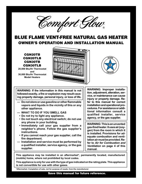
<strong>BLUE</strong> <strong>FLAME</strong> <strong>VENT</strong>-<strong>FREE</strong> <strong>NATURAL</strong> <strong>GAS</strong> <strong>HEATER</strong>OWNER’S OPERATION AND INSTALLATION MANUALCGN20TBCGN20TLBCGN30TBCGN30TLB20,000 Btu/Hr Thermostatand30,000 Btu/Hr ThermostatModel HeatersWARNING: If the information in this manual is notfollowed exactly, a fire or explosion may result causingproperty damage, personal injury, or loss of life.— Do not store or use gasoline or other flammablevapors and liquids in the vicinity of this or anyother appliance.— WHAT TO DO IF YOU SMELL <strong>GAS</strong>• Do not try to light any appliance.• Do not touch any electrical switch; do not useany phone in your building.• Immediately call your gas supplier from aneighbor’s phone. Follow the gas supplier’sinstructions.• If you cannot reach your gas supplier, call thefire department.— Installation and service must be performed bya qualified installer, service agency, or the gassupplier.WARNING: Improper installation,adjustment, alteration, service,or maintenance can causeinjury or property damage. Referto this manual for correctinstallation and operational procedures.For assistance or additionalinformation consult aqualified installer, serviceagency, or the gas supplier.WARNING: This is an unventedgas-fired heater. It uses air (oxygen)from the room in which itis installed. Provisions for adequatecombustion and ventilationair must be provided. Referto Air for Combustion andVentilation on page 4 of thismanual.This appliance may be installed in an aftermarket*, permanently located, manufactured(mobile) home, where not prohibited by local codes.This appliance is only for use with the type of gas indicated on the rating plate. This applianceis not convertible for use with other gases.*Aftermarket: Completion of sale, not for purpose of resale, from the manufacturerSave this manual for future reference.
<strong>BLUE</strong> <strong>FLAME</strong> <strong>NATURAL</strong> <strong>GAS</strong> <strong>HEATER</strong>SAFETYINFORMATIONWARNINGSIMPORTANT: Read this owner’smanual carefully and completelybefore trying to assemble, operate,or service this heater. Improperuse of this heater cancause serious injury or death fromburns, fire, explosion, electricalshock, and carbon monoxidepoisoning.DANGER: Carbon monoxidepoisoning may lead to death!Carbon Monoxide Poisoning: Early signsof carbon monoxide poisoning resemble theflu, with headaches, dizziness, or nausea. Ifyou have these signs, the heater may not beworking properly. Get fresh air at once!Have heater serviced. Some people are moreaffected by carbon monoxide than others.These include pregnant women, people withheart or lung disease or anemia, those underthe influence of alcohol, and those at highaltitudes.Natural Gas: Natural gas is odorless. Anodor-making agent is added to natural gas.The odor helps you detect a natural gas leak.However, the odor added to natural gas canfade. Natural gas may be present even thoughno odor exists.Make certain you read and understand allwarnings. Keep this manual for reference. Itis your guide to safe and proper operation ofthis heater.WARNING: Any change tothis heater or its controls can bedangerous.WARNING: Do not use anyaccessory not approved for usewith this heater.Due to high temperatures, theappliance should be located outof traffic and away from furnitureand draperies.Do not place clothing or otherflammable material on or nearthe appliance. Never place anyobjects on the heater.Surface of heater becomes veryhot when running heater. Keepchildren and adults away fromhot surface to avoid burns orclothing ignition. Heater will remainhot for a time after shutdown.Allow surface to cool beforetouching.Carefully supervise young childrenwhen they are in the sameroom with heater.Make sure grill guard is in placebefore running heater.Keep the appliance area clear andfree from combustible materials,gasoline and other flammablevapors and liquids.1. This appliance is only for use with thetype of gas indicated on the rating plate.This appliance is not convertible for usewith other gases.2. If you smell gas• shut off gas supply• do not try to light any appliance• do not touch any electrical switch; donot use any phone in your building• immediately call your gas supplierfrom a neighbor’s phone. Follow thegas supplier’s instructions• if you cannot reach your gas supplier,call the fire department3. This heater shall not be installed in abedroom or bathroom.4. This heater needs fresh, outside air ventilationto run properly. This heater hasan Oxygen Depletion Sensing (ODS)safety shutoff system. The ODS shutsdown the heater if not enough fresh airis available. See Fresh Air for Combustionand Ventilation, pages 4 through 6.5. Keep air openings in front and bottomof heater clear and free of debris. Thiswill ensure enough air for proper combustion.6. If heater shuts off, do not relight untilyou provide fresh, outside air. If heaterkeeps shutting off, have it serviced.7. Do not run heater• where flammable liquids or vaporsare used or stored• under dusty conditions8. Do not use heater if any part has beenunder water. Immediately call a qualifiedservice technician to inspect theroom heater and to replace any part ofthe control system and any gas controlwhich has been under water.10. Turn off and unplug heater and let coolbefore servicing. Only a qualified serviceperson should service and repairheater.11. Operating heater above elevations of4,500 feet could cause pilot outage.2 104331
OWNER’S MANUALPRODUCTIDENTIFICATIONFrontPanelIgnitor ButtonControl KnobGrillGuardGlassPanelHeaterCabinetPRODUCTFEATURESSAFETY DEVICEThis heater has a pilot with an OxygenDepletion Sensing (ODS) safety shutoffsystem. The ODS/pilot is a required featurefor vent-free room heaters. The ODS/pilotshuts off the heater if there is not enoughfresh air.PIEZO IGNITION SYSTEMThis heater has a piezo ignitor. This systemrequires no matches, batteries, or othersources to light heater.THERMOSTATIC HEATCONTROLThermostat models have a thermostat sensingbulb and a control valve. This results inthe greatest heater comfort. This can alsoresult in lower gas bills.Figure 1 - Vent-Free Natural Gas Heater (30,000 Btu/Hr Model Shown)LOCAL CODESInstall and use heater with care. Follow alllocal codes. In the absence of local codes, usethe latest edition of the National Fuel GasCode ANS Z223.1, also known as NFPA 54*.*Available from:American National Standards Institute, Inc.1430 BroadwayNew York, NY 10018National Fire Protection Association, Inc.Batterymarch ParkQuincy, MA 02269UNPACKING1. Remove heater from carton.2. Remove all protective packaging appliedto heater for shipment.3. Check heater for any shipping damage.If heater is damaged, promptly informdealer where you bought heater.1043313
<strong>BLUE</strong> <strong>FLAME</strong> <strong>NATURAL</strong> <strong>GAS</strong> <strong>HEATER</strong>FRESH AIR FORCOMBUSTION AND<strong>VENT</strong>ILATIONWARNING: This heater shallnot be installed in a confined spaceor unusually tight constructionunless provisions are providedfor adequate combustion and ventilationair. Read the following instructionsto insure proper freshair for this and other fuel-burningappliances in your home.Today’s homes are built more energy efficientthan ever. New materials, increasedinsulation, and new construction methodshelp reduce heat loss in homes. Home ownersweather strip and caulk around windows anddoors to keep the cold air out and the warm airin. During heating months, home ownerswant their homes as airtight as possible.While it is good to make your home energyefficient, your home needs to breathe. Freshair must enter your home. All fuel-burningappliances need fresh air for proper combustionand ventilation.Exhaust fans, fireplaces, clothes dryers, andfuel burning appliances draw air from thehouse to operate. You must provide adequatefresh air for these appliances. Thiswill insure proper venting of vented fuelburningappliances.PROVIDING ADEQUATE<strong>VENT</strong>ILATIONThe following are excerpts from NationalFuel Gas Code. NFPA 54/ANS Z223.1, Section5.3, Air for Combustion and Ventilation.All spaces in homes fall into one of the threefollowing ventilation classifications:1. Unusually Tight Construction2. Unconfined Space3. Confined SpaceThe information on pages 4 through 6 willhelp you classify your space and provideadequate ventilation.Unusually Tight ConstructionThe air that leaks around doors and windowsmay provide enough fresh air forcombustion and ventilation. However, inbuildings of unusually tight construction,you must provide additional fresh air.Unusually tight construction is definedas construction where:a. walls and ceilings exposed to theoutside atmosphere have a continuouswater vapor retarder witha rating of one perm (6 x 10 -11 kgper pa-sec-m 2 ) or less with openingsgasketed or sealed andb. weather stripping has beenadded on openable windows anddoors andc. caulking or sealants are appliedto areas such as joints aroundwindow and door frames, betweensole plates and floors, betweenwall-ceiling joints, betweenwall panels, at penetrationsfor plumbing, electrical, andgas lines, and at other openings.If your home meets all of the threecriteria above, you must provide additionalfresh air. See Ventilation AirFrom Outdoors, page 6.If your home does not meet all of thethree criteria above, proceed to DeterminingFresh-Air Flow For HeaterLocation, page 5.Confined and Unconfined SpaceThe National Fuel Gas Code ANS Z223.1defines a confined space as a space whosevolume is less than 50 cubic feet per 1,000Btu per hour (4.8 m 3 per kw) of the aggregateinput rating of all appliances installedin that space and an unconfined space as aspace whose volume is not less than 50cubic feet per 1,000 Btu per hour (4.8 m 3 perkw) of the aggregate input rating of allappliances installed in that space. Roomscommunicating directly with the space inwhich the appliances are installed*, throughopenings not furnished with doors, are considereda part of the unconfined space.This heater shall not be installed in a confinedspace or unusually tight constructionunless provisions are provided for adequatecombustion and ventilation air.* Adjoining rooms are communicating onlyif there are doorless passageways or ventilationgrills between them.4 104331
FRESH AIR FORCOMBUSTION AND<strong>VENT</strong>ILATIONContinuedDETERMINING FRESH-AIR FLOW FOR <strong>HEATER</strong> LOCATIONOWNER’S MANUALDetermining if You Have a Confined or Unconfined SpaceUse this worksheet to determine if you have a confined or unconfined space.Space: Includes the room in which you will install heater plus any adjoining rooms with doorless passageways or ventilation grills betweenthe rooms.1. Determine the volume of the space (length x width x height).Length x Width x Height = _________________cu. ft. (volume of space)Example: Space size 20 ft. (length) x 16 ft. (width) x 8 ft. (ceiling height) = 2560 cu. ft. (volume of space)If additional ventilation to adjoining room is supplied with grills or openings, add the volume of these rooms to the total volume ofthe space.2. Divide the space volume by 50 cubic feet to determine the maximum Btu/Hr the space can support._________________ (volume of space) ÷ 50 cu. ft. = (Maximum Btu/Hr the space can support)Example: 2560 cu. ft. (volume of space) ÷ 50 cu. ft. = 51.2 or 51,200 (maximum Btu/Hr the space can support)3. Add the Btu/Hr of all fuel burning appliances in the space.Vent-free heater __________________Btu/HrGas water heater* __________________Btu/Hr Example:Gas furnace__________________Btu/Hr Gas water heater 40,000 Btu/HrVented gas heater __________________Btu/Hr Vent-free heater + 20,000 Btu/HrGas fireplace logs __________________Btu/Hr Total = 60,000 Btu/HrOther gas appliances* + __________________Btu/HrTotal= __________________Btu/Hr* Do not include direct-vent gas appliances. Direct-vent draws combustion air from the outdoors and vents to the outdoors.4. Compare the maximum Btu/Hr the space can support with the actual amount of Btu/Hr used._________________ Btu/Hr (maximum the space can support)_________________ Btu/Hr (actual amount of Btu/Hr used)Example: 51,200 Btu/Hr (maximum the space can support)60,000 Btu/Hr (actual amount of Btu/Hr used)The space in the above example is a confined space because the actual Btu/Hr used is more than the maximum Btu/Hr the space can support.You must provide additional fresh air. Your options are as follows:A. Rework worksheet, adding the space of an adjoining room. If the extra space provides an unconfined space, remove door to adjoiningroom or add ventilation grills between rooms. See Ventilation Air From Inside Building, page 6.B. Vent room directly to the outdoors. See Ventilation Air From Outdoors, page 6.C. Install a lower Btu/Hr heater, if lower Btu/Hr size makes room unconfined.If the actual Btu/Hr used is less than the maximum Btu/Hr the space can support, the space is an unconfined space. You will need noadditional fresh air ventilation.WARNING: If the area in which the heater may be operated is smaller than that defined as an unconfined spaceor if the building is of unusually tight construction, provide adequate combustion and ventilation air by one ofthe methods described in the National Fuel Gas Code, ANS Z223.1, Section 5.3 or applicable local codes.Continued1043315
<strong>BLUE</strong> <strong>FLAME</strong> <strong>NATURAL</strong> <strong>GAS</strong> <strong>HEATER</strong>FRESH AIR FORCOMBUSTION AND<strong>VENT</strong>ILATIONContinued<strong>VENT</strong>ILATION AIRVentilation Air From InsideBuildingThis fresh air would come from an adjoiningunconfined space. When ventilating to anadjoining unconfined space, you must providetwo permanent openings: one within12" of the ceiling and one within 12" of thefloor on the wall connecting the two spaces(see options 1 and 2, Figure 2). You can alsoremove door into adjoining room (see option3, Figure 2). Follow the National FuelGas Code NFPA 54/ANS Z223.1, Section5.3, Air for Combustion and Ventilation forrequired size of ventilation grills or ducts.VentilationGrillsinto AdjoiningRoom,Option 1OrRemoveDoor intoAdjoiningRoom,Option 312"12"Ventilation GrillsInto Adjoining Room,Option 2WARNING: Rework worksheet,adding the space of theadjoining unconfined space. Thecombined spaces must haveenough fresh air to supply allappliances in both spaces.Ventilation Air From OutdoorsProvide extra fresh air by using ventilationgrills or ducts. You must provide two permanentopenings: one within 12" of theceiling and one within 12" of the floor.Connect these items directly to the outdoorsor spaces open to the outdoors. These spacesinclude attics and crawl spaces. Follow theNational Fuel Gas Code NFPA 54/ANSZ223.1, Section 5.3, Air for Combustionand Ventilation for required size of ventilationgrills or ducts.IMPORTANT: Do not provide openings forinlet or outlet air into attic if attic has athermostat-controlled power vent. Heated airentering the attic will activate the power vent.Figure 2 - Ventilation Air from Inside BuildingOutletAirInletAirOutletAirInlet AirFigure 3 - Ventilation Air from OutdoorsVentilatedAtticVentilatedCrawl SpaceTo AtticToCrawlSpace6 104331
OWNER’S MANUALINSTALLATIONNOTICE: This heater is intendedfor use as supplemental heat. Usethis heater along with your primaryheating system. Do not installthis heater as your primaryheat source. If you have a centralheating system, you may runsystem’s circulating blower whileusing heater. This will help circulatethe heat throughout thehouse. In the event of a poweroutage, you can use this heateras your primary heat source.WARNING: A qualified serviceperson must install heater.Follow all local codes.CHECK <strong>GAS</strong> TYPEUse only natural gas. If your gas supply isnot natural gas, do not install heater. Calldealer where you bought heater for propertype heater.INSTALLATION ITEMSBefore installing heater, make sure you havethe items listed below.• piping (check local codes)• sealant (resistant to propane/LP gas)• equipment shutoff valve *• ground joint union• test gauge connection *• sediment trap• tee joint• pipe wrench• test gauge connection** A CSA/AGA design-certified equipmentshutoff valve with 1/8" NPT tap is an acceptablealternative to test gauge connection.Purchase the optional CSA/AGA design-certifiedequipment shutoff valve fromyour dealer. See Accessories, page 18.LOCATING <strong>HEATER</strong>This heater is designed to be mounted on awall.WARNING: Maintain the minimumclearances shown in Figure4. If you can, provide greater clearancesfrom floor, ceiling, and joiningwall.You can locate heater on floor, away from awall. An optional floor mounting stand isneeded. Purchase the floor mounting standfrom your dealer. See Accessories, page 18.WARNING: Never install theheater• in a bedroom or a bathroom• in a recreational vehicle• where curtains, furniture,clothing, or other flammableobjects are less than 36 inchesfrom the front, top, or sides ofthe heater• as a fireplace insert• in high traffic areas• in windy or drafty areasCAUTION: This heater createswarm air currents. Thesecurrents move heat to wall surfacesnext to heater. Installingheater next to vinyl or cloth wallcoverings or operating heaterwhere impurities (such as tobaccosmoke, aromatic candles,cleaning fluids, oil or kerosenelamps, etc.) in the air exist, maydiscolor walls.IMPORTANT: Vent-free heaters add moistureto the air. Although this is beneficial,installing heater in rooms without enoughventilation air may cause mildew to form fromtoo much moisture. See Fresh Air for Combustionand Ventilation, pages 4 through 6.CAUTION: If you install theheater in a home garage• heater pilot and burner mustbe at least 18 inches abovefloor• locate heater where moving vehiclewill not hit itFor convenience and efficiency, install heater• where there is easy access for operation,inspection, and service• in coldest part of roomAn optional fan kit is available from yourdealer. See Accessories, page 18. If planningto use fan, locate heater near an electricaloutlet.6"MinimumFromSides OfHeaterLeftSideCEILINGFLOOR36"MinimumRightSideMinimumto TopSurface3" MinimumOf CarpeCombustof Carpeting orOther CombustibleMaterialFigure 4 - Mounting Clearances As ViewedFrom Front of Heater1043317Continued
<strong>BLUE</strong> <strong>FLAME</strong> <strong>NATURAL</strong> <strong>GAS</strong> <strong>HEATER</strong>INSTALLATIONContinuedTHERMOSTAT SENSINGBULBThe thermostat sensing bulb has beenplaced inside the heater for protectionduring shipping.Locating Thermostat SensingBulb1. Remove front panel of heater (see Figure7).2. Locate thermostat sensing bulb justunder burner assembly.IMPORTANT: Attach thermostat sensingbulb to back of heater for proper operation.Attaching Thermostat SensingBulb1. Remove thermostat sensing bulb fromholders inside heater. Route throughslot opening in bottom of heater.2. Place clamp on thermostat sensing bulbas shown in Figure 5. Clamp is providedin hardware package.3. Snap clamp into upper mounting holeas shown in Figure 5. Mounting hole islocated on lower left edge on back ofheater. Make sure the thermostat sensingbulb is pointing up.ThermostatSensingBulbClampFigure 5 - Attaching Thermostat SensingBulbINSTALLING <strong>HEATER</strong> TOWALLMounting BracketLocate mounting bracket in heater carton.Remove mounting bracket from heater carton.Figure 6 - Bracket LocationRemoving Front Panel Of Heater1. Remove two screws near bottom cornersof front panel.2. Lift straight up on grill guard until it stops.Grill guard will slide up about 1/4".3. Pull bottom of front panel forward, thendownward.4. Remove cardboard packing from grilland glass.Figure 7 - Removing Front Panel Of HeaterMethods For AttachingMounting Bracket To WallOnly use last hole on each end of mountingbracket to attach bracket to wall. These twoholes are 16 inches apart from their centers.Attach mounting bracket to wall in one oftwo ways.1. Attaching to wall stud2. Attaching to wall anchorAttaching to wall stud: This method providesthe strongest hold. Insert mountingscrews through mounting bracket and intowall studs.Attaching to wall anchor: This methodallows you to attach mounting bracket tohollow walls (wall areas between studs) orto solid walls (concrete or masonry).Decide which method better suits your needs.Either method will provide a secure hold forthe mounting bracket.Marking Screw Locations1. Tape mounting bracket to wall whereheater will be located. Make suremounting bracket is level.WARNING: Maintain minimumclearances shown in Figure 8. Ifyou can, provide greater clearancesfrom floor and joining wall.2. Mark screw locations on wall (see Figure8).Note: Only mark last hole on each endof mounting bracket. Insert mountingscrews through these holes only.3. Remove tape and mounting bracketfrom wall.Adjoining WallAdjoining Wall11"Min.7 1/4"Min.16"Only Insert MountingScrews Through LastHole On Each EndFloor30,000 Btu/Hr Model16"Only Insert MountingScrews Through LastHole On Each End18 3/4"Min.18 3/4"Min.Floor20,000 Btu/Hr ModelsFigure 8 - Mounting Bracket Clearances8 104331
OWNER’S MANUALINSTALLATIONContinuedAttaching Mounting Bracket ToWallNote: Wall anchors, mounting screws, andspacers are in hardware package. The hardwarepackage is provided with heater.Attaching to wall stud methodFor attaching mounting bracket to wall studs.1. Drill holes at marked locations using9/64" drill bit.2. Place mounting bracket onto wall. Lineup last hole on each end of bracket withholes drilled in wall.3. Insert mounting screws through bracketand into wall studs.4. Tighten screws until mounting bracketis firmly fastened to wall studs.Attaching to wall anchor methodFor attaching mounting bracket to hollowwalls (wall areas between studs) or solidwalls (concrete or masonry).1. Drill holes at marked locations using5/16" drill bit. For solid walls (concreteor masonry), drill at least 1" deep.2. Fold wall anchor as shown in Figure 9.3. Insert wall anchor (wings first) intohole. Tap anchor flush to wall.4. For thin walls (1/2" or less), insert redkey into wall anchor. Push red key to“pop” open anchor wings.IMPORTANT: Do not hammer key!For thick walls (over 1/2" thick) or solidwalls, do not pop open wings.5. Place mounting bracket onto wall. Lineup last hole on each end of bracket withwall anchors.6. Insert mounting screws through bracketand into wall anchors.7. Tighten screws until mounting bracketis firmly fastened to wall.Figure 9 - Folding AnchorFigure 10 - Popping Open Anchor WingsFor Thin WallsPlacing Heater On MountingBracket1. Locate two horizontal slots on backpanel of heater.2. Place heater onto mounting bracket.Slide horizontal slots onto stand-outtabs on mounting bracket.Stand-Out TabHorizontal SlotsMounting Bracket(attached to wall)Figure 11 - Mounting Heater OntoMounting BracketInstalling Bottom MountingScrews1. Locate two bottom mounting holes.These holes are near bottom on backpanel of heater (see Figure 12).2. Mark screw locations on wall.3. Remove heater from mounting bracket.4. If installing bottom mounting screwsinto hollow or solid wall, install wallanchors. Follow steps 1 through 4 underAttaching To Wall Anchor Method.If installing bottom mounting screwinto wall stud, drill holes at marked locationsusing 9/64" drill bit.5. Replace heater onto mounting bracket.6. Place spacers between bottom mountingholes and wall anchor or drilled hole.7. Hold spacer in place with one hand.With other hand, insert mounting screwthrough bottom mounting hole andspacer. Place tip of screw in openingof wall anchor or drilled hole.8. Tighten both screws until heater isfirmly secured to wall. Do not overtighten.Note: Do not replace front panel at thistime. Replace front panel after makinggas connections and checking for leaks(see pages 10 and 11). Make gas connectionsand check for leaks before replacingfront panel (see pages 10 and 11).Figure 12 - Installing Bottom MountingScrews1043319Continued
<strong>BLUE</strong> <strong>FLAME</strong> <strong>NATURAL</strong> <strong>GAS</strong> <strong>HEATER</strong>INSTALLATIONContinuedCONNECTING TO <strong>GAS</strong>SUPPLYWARNING: This appliance requiresa 3/8" NPT (National PipeThread) inlet connection to thepressure regulator.Apply pipe joint sealant lightly to malethreads. This will prevent excess sealantfrom going into pipe. Excess sealant in pipecould result in clogged heater valves.CAUTION: Use pipe joint sealantthat is resistant to liquid petroleum(LP) gas.Install sediment trap in supply line as shownin Figure 13. Locate sediment trap where itis within reach for cleaning. Locate sedimenttrap where trapped matter is not likelyto freeze. A sediment trap traps moistureand contaminants. This keeps them fromgoing into heater controls. If sediment trapis not installed or is installed wrong, heatermay not run properly.IMPORTANT: Hold pressure regulator withwrench when connecting it to gas pipingand/or fittings.WARNING: A qualified serviceperson must connect heater to gassupply. Follow all local codes.WARNING: Never connectheater to private (non-utility) gaswells. This gas is commonlyknown as wellhead gas.PressureRegulatorIMPORTANT: Check gas line pressurebefore connecting heater to gas line. Gasline pressure must be no greater than 14inches of water. If gas line pressure is higher,heater regulator damage could occur.3/8" NPTPipe NippleGround Joint UnionHeaterCabinetCAUTION: Use only new,black iron or steel pipe. Internally-tinnedcopper tubing maybe used in certain areas. Checkyour local codes. Use pipe of largeenough diameter to allow propergas volume to heater. If pipe istoo small, undue loss of pressurewill occur.Typical Inlet Pipe Diameters20,000 Btu/Hr Models 3/8" or greater30,000 Btu/Hr Models 1/2" or greaterInstallation must include an equipmentshutoff valve, union, and plugged 1/8" NPTtap. Locate NPT tap within reach for testgauge hook up. NPT tap must be upstreamfrom heater (see Figure 13).IMPORTANT: Install an equipment shutoffvalve in an accessible location. The equipmentshutoff valve is for turning on orshutting off the gas to the appliance.TestGaugeConnection *SedimentTrapTee JointReducerBushing to1/8" NPT1/8" NPTPlug TapTee JointPipe NippleCap3" MinimumEquipmentShutoffValve *Typical InletPipe from GasMeter (5" W.C.to 10.5" W.C.Pressure)Figure 13 - Gas Connection* A CSA/AGA design-certified equipment shutoff valve with 1/8" NPT tap is an acceptablealternative to test gauge connection. Purchase the optional CSA/AGA design-certifiedequipment shutoff valve from your dealer. See Accessories, page 18.10 104331
OWNER’S MANUALINSTALLATIONContinuedCHECKING <strong>GAS</strong>CONNECTIONSWARNING: Test all gas pipingand connections for leaksafter installation or servicing.Correct all leaks at once.WARNING: Never use an openflame to check for a leak. Apply amixture of liquid soap and waterto all joints. Bubbles formingshow a leak. Correct all leaks atonce.Pressure Testing Gas SupplyPiping SystemTest Pressures In Excess Of 1/2 PSIG(3.5 kPa)1. Disconnect appliance with its appliancemain gas valve (control valve) and equipmentshutoff valve from gas supply pipingsystem. Pressures in excess of 1/2 psigwill damage heater regulator.2. Cap off open end of gas pipe whereequipment shutoff valve was connected.3. Pressurize supply piping system by eitherusing compressed air or opening main gasvalve located on or near gas meter.4. Check all joints of gas supply pipingsystem. Apply mixture of liquid soapand water to gas joints. Bubbles formingshow a leak.5. Correct all leaks at once.6. Reconnect heater and equipmentshutoff valve to gas supply. Check reconnectedfittings for leaks.Test Pressures Equal To or Less Than 1/2PSIG (3.5 kPa)1. Close equipment shutoff valve (see Figure14).2. Pressurize supply piping system by eitherusing compressed air or opening main gasvalve located on or near gas meter.3. Check all joints from gas meter to equipmentshutoff valve (see Figure 15). Applymixture of liquid soap and water togas joints. Bubbles forming show a leak.4. Correct all leaks at once.Pressure Testing Heater GasConnections1. Open equipment shutoff valve (see Figure14).2. Open main gas valve located on or neargas meter.3. Make sure control knob of heater is inthe OFF position.4. Check all joints from equipment shutoffvalve to thermostat gas valve (see Figure15). Apply mixture of liquid soapand water to gas joints. Bubbles formingshow a leak.5. Correct all leaks at once.6. Light heater (see Operating Heater,pages 11 and 12). Check the rest of theinternal joints for leaks.7. Turn off heater (see To Turn Off Gas toAppliance, page 12).8. Replace front panel.EquipmentShutoffValveONPOSITOPOSClosedFigure 14 - Equipment Shutoff ValveGas MeterOpenThermostat Gas ValveFigure 15 - Checking Gas JointsEquipmentShutoffValveOPERATING<strong>HEATER</strong>FOR YOUR SAFETYREAD BEFORELIGHTINGWARNING: If you do not followthese instructions exactly, afire or explosion may result causingproperty damage, personalinjury or loss of life.A. This appliance has a pilot which mustbe lighted by hand. When lighting thepilot, follow these instructions exactly.B. BEFORE LIGHTING smell allaround the appliance area for gas. Besure to smell next to the floor becausesome gas is heavier than air and willsettle on the floor.WHAT TO DO IF YOU SMELL <strong>GAS</strong>• Do not try to light any appliance.• Do not touch any electric switch; donot use any phone in your building.• Immediately call your gas supplierfrom a neighbor’s phone. Followthe gas supplier’s instructions.• If you cannot reach your gas supplier,call the fire department.C. Use only your hand to push in or turnthe gas control knob. Never use tools.If the knob will not push in or turnby hand, don’t try to repair it, call aqualified service technician or gassupplier. Force or attempted repairmay result in a fire or explosion.D. Do not use this appliance if any parthas been under water. Immediatelycall a qualified service technician toinspect the appliance and to replaceany part of the control system andany gas control which has been underwater.Continued10433111
<strong>BLUE</strong> <strong>FLAME</strong> <strong>NATURAL</strong> <strong>GAS</strong> <strong>HEATER</strong>OPERATING<strong>HEATER</strong>LIGHTINGINSTRUCTIONS1. STOP! Read the safety information,column 3, page 11.2. Make sure equipment shutoff valveis fully open.3. Turn control knob clockwise Clockwiseto the OFF position.4. Wait five (5) minutes to clear out anygas. Then smell for gas, includingnear the floor. If you smell gas,STOP! Follow “B” in the safety information,column 3, page 11. If youdon’t smell gas, go to the next step.5. Turn control knob counterclockwiseC-clockwise to the PILOT position.Press in control knob for five (5) seconds(see Figure 16).Note: You may be running thisheater for the first time after hookingup to gas supply. If so, the controlknob may need to be pressed infor 30 seconds. This will allow air tobleed from the gas system.• If control knob does not pop upwhen released, contact a qualifiedservice person or gas supplier forrepairs.6. With control knob pressed in, pushdown and release ignitor button. Thiswill light pilot. The pilot is attachedto the front of burner. The pilot canbe seen through the glass panel. Ifneeded, keep pressing ignitor buttonuntil pilot lights.Note: If pilot does not stay lit, referto Troubleshooting, pages 14 through16. Also contact a qualified serviceperson or gas supplier for repairs.Until repairs are made, light pilotwith match. To light pilot with match,see Manual Lighting Procedure.7. Keep control knob pressed in for 30seconds after lighting pilot. After 30seconds, release control knob.Note: If pilot goes out, repeat steps3 through 7. This heater has a safetyinterlock system. Wait one (1) minutebefore lighting pilot again.8. Turn control knob counterclockwiseC-clockwise to desired heating level. Themain burner should light. Set controlknob to any heat level between HIand LO.CAUTION: Do not try to adjustheating levels by using theequipment shutoff valve.Ignitor ButtonIGNITORPILOTOFFHILOControl KnobFigure 16 - Control Knob In The OFFPositionThermocoupleFigure 17 - PilotIgnitor ElectrodePilot BurnerTO TURN OFF <strong>GAS</strong>TO APPLIANCEShutting Off Heater1. Turn control knob clockwiseClockwise to the OFF position.2. Turn off all electric power to the applianceif service is to be performed.Shutting Off Burner Only (pilotstays lit)Turn control knob clockwise Clockwise tothe PILOT position.THERMOSTATCONTROL OPERATIONThe thermostatic control used on thesemodels differs from standard thermostats.Standard thermostats simply turnon and off the burner. The thermostatused on this heater senses the room temperature.The thermostat adjusts theamount of gas flow to the burner. Thisincreases or decreases the burner flameheight. At times the room may exceed theset temperature. If so, the burner willshut off. The burner will cycle back onwhen room temperature drops below theset temperature. The control knob can beset to any heat level between HI and LO.Note: The thermostat sensing bulb measuresthe temperature of air near theheater cabinet. This may not always agreewith room temperature (depending onhousing construction, installation location,room size, open air temperatures,etc.). Frequent use of your heater will letyou determine your own comfort levels.MANUAL LIGHTINGPROCEDURE1. Remove front panel (see Figure 7,page 8).2. Follow steps 1 through 5 under LightingInstructions.3. With control knob pressed in, strikematch. Hold match to pilot until pilotlights.4. Keep control knob pressed in for 30seconds after lighting pilot. After 30seconds, release control knob. Nowfollow step 8, column 2.5. Replace front panel.12 104331
OWNER’S MANUALINSPECTINGBURNERCheck pilot flame pattern and burner flamepattern often.PILOT <strong>FLAME</strong> PATTERNFigure 18 shows a correct pilot flame pattern.Figure 19 shows an incorrect pilotflame pattern. The incorrect pilot flame isnot touching the thermocouple. This willcause the thermocouple to cool. When thethermocouple cools, the heater will shutdown.If pilot flame pattern is incorrect, as shownin Figure 19.• turn heater off (see To Turn Off Gas toAppliance, page 12)• see Troubleshooting, pages 14 through 16ThermocouplePilot BurnerFigure 18 - Correct Pilot Flame PatternThermocouplePilot BurnerWARNING: If yellow tippingoccurs, your heater could produceincreased levels of carbonmonoxide. If burner flame patternshows yellow tipping, follow instructionsat bottom of this page.NOTICE: Do not mistake orangeflames with yellow tipping. Dirtor other fine particles enter theheater and burn causing briefpatches of orange flame.If burner flame pattern is incorrect, as shownin Figure 21• turn heater off (see To Turn Off Gas toAppliance, page 12)• see Troubleshooting, pages 14 through 16Figure 20 - Correct Burner Flame PatternYellowTipping1/2 GLASS HEIGHTFigure 21 - Incorrect Burner Flame PatternCLEANING ANDMAINTENANCE1/2 GLASS HEIGHTWARNING: Turn off heaterand let cool before cleaning.CLEANING BURNERPILOT AIR INLET HOLEWe recommend that you clean the unit every2,500 hours of operation or every threemonths.We also recommend that you keep the burnertube and pilot assembly clean and free of dustand dirt. To clean these parts we recommendusing compressed air no greater than 30 PSI.Your local computer store, hardware store, orhome center may carry compressed air in acan. You can use a vacuum cleaner in theblow position. If using compressed air in acan, please follow the directions on the can.If you don't follow directions on the can, youcould damage the pilot assembly.1. Shut off the unit, including the pilot.Allow the unit to cool for at least thirtyminutes.2. Inspect burner, pilot for dust and dirt.3. Blow air through the ports/slots andholes in the burner.Clean the pilot assembly also. A yellow tipon the pilot flame indicates dust and dirt inthe pilot assembly. There is a small pilot airinlet hole about two inches from where thepilot flame comes out of the pilot assembly(see Figure 22). With the unit off, lightlyblow air through the air inlet hole. You mayblow through a drinking straw if compressedair is not available.Pilot Air InletHolePilot AssemblyFigure 19 - Incorrect Pilot Flame PatternBURNER <strong>FLAME</strong> PATTERNFigure 20 shows a correct burner flamepattern. Figure 21 shows an incorrect burnerflame pattern. The incorrect burner flamepattern shows yellow tipping of the flame. Italso shows the flame higher than 1/2 theglass panel height.CAUTION: You must keepcontrol areas, burner, and circulatingair passageways of heaterclean. Inspect these areas ofheater before each use. Haveheater inspected yearly by a qualifiedservice person. Heater mayneed more frequent cleaning dueto excessive lint from carpeting,bedding material, pet hair, etc.ODS/PILOT AND BURNER• Use a vacuum cleaner, pressurized air,or small, soft bristled brush to clean.Figure 22 - Pilot Inlet Air HoleCABINETAir Passageways• Use a vacuum cleaner or pressurized airto clean.Exterior• Use a soft cloth dampened with a mildsoap and water mixture. Wipe the cabinetto remove dust.10433113
<strong>BLUE</strong> <strong>FLAME</strong> <strong>NATURAL</strong> <strong>GAS</strong> <strong>HEATER</strong>TROUBLESHOOTINGNote: For additional help, visit DESAInternational’s technical service web siteat www.desatech.com.Note: All troubleshooting items are listed inorder of operation.OBSERVED PROBLEMWhen ignitor button is pressed, there is nospark at ODS/pilotWhen ignitor button is pressed, there isspark at ODS/pilot but no ignitionODS/pilot lights but flame goes out whencontrol knob is releasedWARNING: Turn off and unplugheater and let cool beforeservicing. Only a qualified serviceperson should service andrepair heater.POSSIBLE CAUSE1. Ignitor electrode positioned wrong2. Ignitor electrode broken3. Ignitor electrode not connected to ignitorcable4. Ignitor cable pinched or wet5. Piezo ignitor nut is loose6. Broken ignitor cable7. Bad piezo ignitor1. Gas supply turned off or equipmentshutoff valve closed2. Control knob not in PILOT position3. Control knob not pressed in while inPILOT position4. Air in gas lines when installed5. ODS/pilot is clogged6. Gas regulator setting is not correct1. Control knob not fully pressed in2. Control knob not pressed in long enough3. Safety interlock system has been triggered(Thermostat models only)4. Manual shutoff valve not fully open5. Thermocouple connection loose at controlvalve6. Pilot flame not touching thermocouple,which allows thermocouple to cool,causing pilot flame to go out. This problemcould be caused by one or both ofthe following:A) Low gas pressureB) Dirty or partially clogged ODS/pilot7. Thermocouple damaged8. Control valve damagedCAUTION: Never use a wire,needle, or similar object to cleanODS/pilot. This can damage ODS/pilot unit.REMEDY1. Replace ignitor2. Replace ignitor3. Reconnect ignitor cable4. Free ignitor cable if pinched by anymetal or tubing. Keep ignitor cable dry5. Tighten nut holding piezo ignitor toheater cabinet. Nut is located insideheater cabinet at top6. Replace ignitor cable7. Replace piezo ignitor1. Turn on gas supply or open equipmentshutoff valve2. Turn control knob to PILOT position3. Press in control knob while in PILOTposition4. Continue holding down control knob.Repeat igniting operation until air isremoved5. Clean ODS/pilot (see Cleaning andMaintenance, page 13) or replace ODS/pilot assembly6. Replace gas regulator1. Press in control knob fully2. After ODS/pilot lights, keep controlknob pressed in 30 seconds3. Wait one (1) minute for safety interlocksystem to reset. Repeat ignition operation4. Fully open equipment shutoff valve5. Hand tighten until snug, then tighten 1/4turn more6. A) Contact local natural gas companyB) Clean ODS/pilot (see Cleaning andMaintenance, page 13) or replace ODS/pilot assembly7. Replace thermocouple8. Replace control valvewww.desatech.com14 104331
OWNER’S MANUALTROUBLESHOOTINGContinuedOBSERVED PROBLEMBurner does not light after ODS/pilot is litDelayed ignition of burnerBurner backfiring during combustionYellow flame during burner combustionSlight smoke or odor during initial operationHeater produces a whistling noise whenburner is litPOSSIBLE CAUSE1. Burner orifice is clogged2. Burner orifice diameter is too small3. Inlet gas pressure is too low1. Manifold pressure is too low2. Burner orifice is clogged1. Burner orifice is clogged or damaged2. Burner damaged3. Gas regulator defective1. Not enough air2. Gas regulator defective1. Residues from manufacturing processes1. Turning control knob to HI positionwhen burner is cold2. Air in gas line3. Air passageways on heater blocked4. Dirty or partially clogged burner orificeREMEDY1. Clean burner (see Cleaning and Maintenance,page 13) or replace burner orifice2. Replace burner orifice3. Contact local natural gas company1. Contact local natural gas company2. Clean burner (see Cleaning and Maintenance,page 13) or replace burner orifice1. Clean burner (see Cleaning and Maintenance,page 13) or replace burner orifice2. Replace burner3. Replace gas regulator1. Check burner for dirt and debris. Iffound, clean burner (see Cleaning andMaintenance, page 13)2. Replace gas regulator1. Problem will stop after a few hours ofoperation1. Turn control knob to LO position andlet warm up for a minute2. Operate burner until air is removed fromline. Have gas line checked by localnatural gas company3. Observe minimum installation clearances(see Figure 4, page 7)4. Clean burner (see Cleaning and Maintenance,page 13) or replace burner orifice104331www.desatech.com15Continued
<strong>BLUE</strong> <strong>FLAME</strong> <strong>NATURAL</strong> <strong>GAS</strong> <strong>HEATER</strong>TROUBLESHOOTINGContinuedWARNING: If you smell gas• Shut off gas supply.• Do not try to light any appliance.• Do not touch any electrical switch; do not use any phone in yourbuilding.• Immediately call your gas supplier from a neighbor’s phone. Follow thegas supplier’s instructions.• If you cannot reach your gas supplier, call the fire department.IMPORTANT: Operating heater where impurities in air exist may create odors. Cleaningsupplies, paint, paint remover, cigarette smoke, cements and glues, new carpet or textiles,etc., create fumes. These fumes may mix with combustion air and create odors.OBSERVED PROBLEMHeater produces a clicking/ticking noisejust after burner is lit or shut offHeater produces unwanted odorsHeater shuts off in use (ODS operates)Gas odor even when control knob is in OFFpositionGas odor during combustionMoisture/condensation noticed on windowsPOSSIBLE CAUSE1. Metal expanding while heating or contractingwhile cooling1. Heater burning vapors from paint, hairspray, glues, etc. (see IMPORTANTstatement above)2. Gas leak. See Warning statement attop of page1. Not enough fresh air is available2. Low line pressure3. ODS/pilot is partially clogged1. Gas leak. See Warning statement attop of page2. Control valve defective1. Foreign matter between control valveand burner2. Gas leak. See Warning statement attop of page1. Not enough combustion/ventilation airREMEDY1. This is common with most heaters. Ifnoise is excessive, contact qualified serviceperson1. Ventilate room. Stop using odor causingproducts while heater is running2. Locate and correct all leaks (see CheckingGas Connections, page 11)1. Open window and/or door for ventilation2. Contact local natural gas company3. Clean ODS/pilot (see Cleaning andMaintenance, page 13)1. Locate and correct all leaks (see CheckingGas Connections, page 11)2. Replace control valve1. Take apart gas tubing and remove foreignmatter2. Locate and correct all leaks (see CheckingGas Connections, page 11)1. Refer to Air for Combustion and Ventilationrequirements (page 4)www.desatech.com16 104331
OWNER’S MANUALSPECIFICATIONSCGN20TB/CGN20TLB CGN30TB/CGN30TLB20,000 Btu/Hr Models 30,000 Btu/Hr ModelsBtu (Variable) 10,000/20,000 15,000/30,000Type Gas Natural Only Natural OnlyIgnition Piezo PiezoPressure Regulator Setting 3" W.C. 3" W.C.Inlet Gas Pressure (in. of water)Maximum 10.5" 10.5”Minimum 5" 5"Dimensions, Inches (H x W x D)Heater 23.5 x 18.5 x 8.0 23.5 x 25.9 x 8.0Carton 25.8 x 21.3 x 10.1 25.8 x 28.7 x 10.1Weight (pounds)Heater 22 30Shipping 27 35TECHNICALSERVICEYou may have further questions about installation,operation, or troubleshooting.If so, contact DESA International’s TechnicalService Department at 1-800-323-5190.You can also visit DESA International’stechnical service web site atwww.desatech.com.SERVICEPUBLICATIONSYou can purchase a service manual from theaddress listed on the back page of this manual.Send a check for $5.00 payable to DESAInternational.SERVICE HINTSWhen Gas Pressure Is Too Low• pilot will not stay lit• burner will have delayed ignition• heater will not produce specified heatWhen Gas Quality Is Bad• pilot will not stay lit• burner will produce flames and soot• heater will backfire when litYou may feel your gas pressure is too low orgas quality is bad. If so, contact your localnatural gas supplier.REPLACEMENTPARTSNote: Use only original replacement parts.This will protect your warranty coveragefor parts replaced under warranty.PARTS UNDER WARRANTYContact authorized dealers of this product. Ifthey can’t supply original replacement part(s),either contact your nearest Parts Central (page19) or call DESA International’s TechnicalService Department at 1-800-323-5190 forreferral information.When calling DESA International, have ready• your name• your address• model and serial numbers of your heater• how heater was malfunctioning• type of gas used (propane/LP or natural gas)• purchase dateUsually, we will ask you to return the defectivepart to the factory.PARTS NOT UNDERWARRANTYContact authorized dealers of this product.If they can’t supply original replacementpart(s), either contact your nearest PartsCentral (page 19) or call DESAInternational’s Parts Department at 1-800-972-7879 for referral information.When calling DESA International, have ready:• model number of your heater• the replacement part number10433117
<strong>BLUE</strong> <strong>FLAME</strong> <strong>NATURAL</strong> <strong>GAS</strong> <strong>HEATER</strong>ACCESSORIESPurchase these heater accessories from yourlocal dealer. If they can not supply theseaccessories, either contact your nearest PartsCentral (see page 19) or call DESAInternational’s Parts Department at 1-800-972-7879 for referral information. You canalso write to the address listed on the backpage of this manual.EQUIPMENT SHUTOFFVALVE GA5010For all models. Equipment shutoff valvewith 1/8" NPT tap.FAN KITS - GA3100(A,B) ANDGA3200T(A,B)For all models. Provides better heat distribution.Makes heater more efficient. Completeinstallation and operating instructionsincluded.Manually-controlled - GA3100(A,B). IncludesON/OFF switch.Thermostatically-controlled - GA3200T(A,B).Includes three settings: ON/OFF/AUTO.FLOOR MOUNTING STAND20,000 Btu/Hr ModelsCGN20TLB - GA4500L - IvoryCGN20TB - GA4500 -Champagne30,000 Btu/Hr ModelsCGN30TLB - GA4510L - IvoryCGN30TB - GA4510 -ChampagneFor locating heater on the floor, away froma wall. Complete installation instructionsincluded.18 104331
OWNER’S MANUALPARTS CENTRALSThese Parts Centrals are privately owned businesses. They have agreed to support ourcustomer’s needs by providing original replacement parts and accessories.Baltimore Electric1348 Dixwell AvenueHamden, CT 06514-03221-800-397-7553203-248-7553Parts DepartmentPortable Heater Parts342 N. County Rd. 400 EastValparaiso, IN 46383-9704All States219-462-74411-800-362-6951sales@portableheaterparts.comtechservice@portableheaterparts.comFBD1349 Adams StreetBowling Green, KY 42103-3414270-846-11991-800-654-8534Fax: 1-800-846-0090franktalk@aol.comMaster Parts Dist.1251 Mound Ave. NWGrand Rapids, MI 49504-2672616-791-05051-800-446-1446Fax: 616-791-8270www.nbmc.comWasher Equipment Co.1715 Main StreetKansas City, MO 64108-2195KS, MO, AR816-842-3911www.washerparts.comEast Coast Energy Products707 BroadwayW. Long Branch, NJ 07764-1542732-870-88091-800-755-8809www.njplaza.com/ecepTarantin Tank Co.P.O. Box 6129Freehold, NJ 07728-6129908-780-93401-800-922-0724www.tarantin.comHeater and Fireplace Store58 Halbe LaneCape May Court, NJ 08210-1110609-390-9774Parts DepartmentDayton HardwareP.O. Box 275North Dayton StationDayton, OH 45404-0275All States937-258-3721OH 1-800-762-3426Halco Enterprises208 Carter Drive, Unit 21West Chester, PA 19382-4500610-430-77171-800-368-0803www.halcoenterprises.comLA Porte’s Parts & Service2444 N. 5th StreetHartsville, SC 29550-7704803-332-0191Parts DepartmentCans Unlimited, Inc.P.O. Box 645Taylor, SC 29687-0013All States803-879-30091-800-845-5301cuisales@aol.com10433119
<strong>BLUE</strong> <strong>FLAME</strong> <strong>NATURAL</strong> <strong>GAS</strong> <strong>HEATER</strong>ILLUSTRATEDPARTSBREAKDOWNCGN20TBCGN20TLBCGN30TBCGN30TLB2021221015122441113239101714193658718162711-111-2120 104331
OWNER’S MANUALPARTS LISTCGN20TBCGN20TLBCGN30TBCGN30TLBThis list contains replaceable parts used in your heater. When ordering parts, follow the instructionslisted under Replacement Parts on page 17 of this manual.PART NUMBER FORKEY CGN20TB/CGN20TLB CGN30TB/CGN30TLBNO. 20,000 Btu/Hr 30,000 Btu/Hr DESCRIPTION QTY.1 098304-01 098304-01 Screw, #10 x 3/8" 22 098742-03 098742-04 Front Panel for CGN20TB/CGN30TB (Champagne) 1098742-19 098742-20 Front Panel for CGN20TLB/CGN30TLB (Ivory) 13 103476-01 103476-02 Grill Guard 14 101108-01 101108-01 Removable Speed Clip 25 104189-01 104189-02 Bottom Glass Retainer 16 098260-09 098260-10 Glass Panel 17 M11084-26 M11084-26 Screw, #10 x 3/8" 48 104618-01BR 104618-02BR Deflector Unit 19 098271-03 098271-03 Ignitor Cable 110 098249-01 098249-01 Nut, M5 211 103594-05 103594-05 ODS/Pilot Assembly 111-1 098514-01 098514-01 Thermocouple 111-2 106842-01 106842-01 Ignitor Electrode 112 103446-01 103447-01 Burner 113 099387-03 099387-03 3/16" Pilot Tubing 114 103845-06 103845-08 Injector 115 099066-01 099066-01 Mounting Bracket 116 099415-07 099415-11 Pressure Regulator 117 099553-01 099553-01 Pilot Shield 118 103255-01 103255-01 3/8" Outlet (Burner) Tubing 119 103256-01 103256-01 3/8" Inlet Tubing 120 098522-10 098522-12 Thermostat Gas Valve 121 104617-03 104617-04 Cabinet for CGN20TB/CGN30TB (Woodgrain) 1104617-05 104617-06 Cabinet for CGN20TLB/CGN30TLB (Ivory) 122 097159-04 097159-04 Piezo Ignitor 123 M11084-38 M11084-38 Screw, #8 x 3/8" 224 NJF-8C NJF-8C Hex Nut 1PARTS AVAILABLE — NOT SHOWN098305-01 098305-01 Control Position Label (CGN20TB/CGN30TB 1Champagne)098305-05 098305-05 Control Position Label (CGN20TLB/CGN30TLB 1Ivory)100642-01 100642-01 Hardware Assembly 110433121
WARRANTY INFORMATIONKEEP THIS WARRANTYModelSerial No.Date PurchasedAlways specify model and serial numbers when communicating with the factory.We reserve the right to amend these specifications at any time without notice. The only warranty applicable is our standard writtenwarranty. We make no other warranty, expressed or implied.LIMITED WARRANTYCOMFORT GLOW <strong>VENT</strong>-<strong>FREE</strong> <strong>NATURAL</strong> <strong>GAS</strong> <strong>HEATER</strong>SDESA International warrants this product to be free from defects in materials and components for two (2) years from the dateof first purchase, provided that the product has been properly installed, operated and maintained in accordance with all applicableinstructions. To make a claim under this warranty the Bill of Sale or cancelled check must be presented.This warranty is extended only to the original retail purchaser. This warranty covers the cost of part(s) required to restore thisheater to proper operating condition and an allowance for labor when provided by a DESA Authorized Service Center. Warrantypart(s) MUST be obtained through authorized dealers of this product and/or DESA International who will provide originalfactory replacement parts. Failure to use original factory replacement parts voids this warranty. The heater MUST be installedby a qualified installer in accordance with all local codes and instructions furnished with the unit.This warranty does not apply to parts that are not in original condition because of normal wear and tear, or parts that fail or becomedamaged as a result of misuse, accidents, lack of proper maintenance or defects caused by improper installation. Travel, diagnostic cost,labor, transportation and any and all such other costs related to repairing a defective heater will be the responsibility of the owner.TO THE FULL EXTENT ALLOWED BY THE LAW OF THE JURISDICTION THAT GOVERNS THE SALE OF THEPRODUCT; THIS EXPRESS WARRANTY EXCLUDES ANY AND ALL OTHER EXPRESSED WARRANTIES ANDLIMITS THE DURATION OF ANY AND ALL IMPLIED WARRANTIES, INCLUDING WARRANTIES OF MER-CHANTABILITY AND FITNESS FOR A PARTICULAR PURPOSE TO TWO (2) YEARS FROM THE DATE OF FIRSTPURCHASE; AND DESA INTERNATIONAL’S LIABILITY IS HEREBY LIMITED TO THE PURCHASE PRICE OF THEPRODUCT AND DESA INTERNATIONAL SHALL NOT BE LIABLE FOR ANY OTHER DAMAGES WHATSOEVERINCLUDING INDIRECT, INCIDENTAL OR CONSEQUENTIAL DAMAGES.Some states do not allow a limitation on how long an implied warranty lasts or an exclusion or limitation of incidental or consequentialdamages, so the above limitation on implied warranties, or exclusion or limitation on damages may not apply to you.This warranty gives you specific legal rights, and you may also have other rights that vary from state to state.For information about this warranty write:INTERNATIONAL2701 Industrial DriveP.O. Box 90004Bowling Green, KY 42102-9004www.desatech.com104331 01NOT A UPC104331-01Rev. C02/00