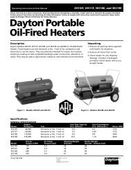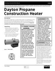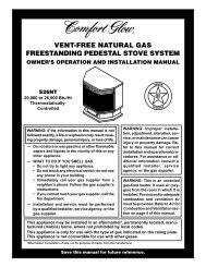
BLUE FLAME VENT-FREE NATURAL GAS HEATER - Desa
BLUE FLAME VENT-FREE NATURAL GAS HEATER - Desa
BLUE FLAME VENT-FREE NATURAL GAS HEATER - Desa

You also want an ePaper? Increase the reach of your titles
YUMPU automatically turns print PDFs into web optimized ePapers that Google loves.
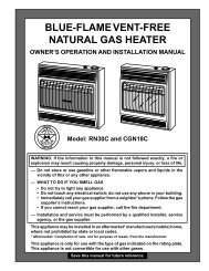
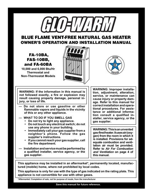
<strong>BLUE</strong> <strong>FLAME</strong> <strong>VENT</strong>-<strong>FREE</strong> <strong>NATURAL</strong> <strong>GAS</strong> <strong>HEATER</strong>OWNER’S OPERATION AND INSTALLATION MANUALFA-10BA,FAS-10BB,and FA-60BA10,000 and 6,000 Btu/HrThermostat andNon-Thermostat ModelsWARNING: If the information in this manual isnot followed exactly, a fire or explosion mayresult causing property damage, personal injury,or loss of life.— Do not store or use gasoline or otherflammable vapors and liquids in the vicinityof this or any other appliance.— WHAT TO DO IF YOU SMELL <strong>GAS</strong>• Do not try to light any appliance.• Do not touch any electrical switch; do notuse any phone in your building.• Immediately call your gas supplier from aneighbor’s phone. Follow the gassupplier’s instructions.• If you cannot reach your gas supplier, callthe fire department.— Installation and service must be performed bya qualified installer, service agency, or thegas supplier.WARNING: Improper installation,adjustment, alteration,service, or maintenance cancause injury or property damage.Refer to this manual forcorrect installation and operationalprocedures. For assistanceor additional informationconsult a qualified installer,service agency, or thegas supplier.WARNING: This is an unventedgas-fired heater. It uses air (oxygen)from the room in which itis installed. Provisions for adequatecombustion and ventilationair must be provided.Refer to Air For Combustionand Ventilation on page 4 ofthis manual.This appliance may be installed in an aftermarket*, permanently located, manufactured(mobile) home, where not prohibited by local codes.This appliance is only for use with the type of gas indicated on the rating plate. Thisappliance is not convertible for use with other gases.*Aftermarket: Completion of sale, not for purpose of resale, from the manufacturerSave this manual for future reference.
PRODUCTIDENTIFICATIONFrontPanelControl KnobGrillGuardGlassPanelHeaterCabinetOWNER’S MANUALPRODUCTFEATURESSAFETY DEVICEThis heater has a pilot with an OxygenDepletion Sensing (ODS) safety shutoff system.The ODS/pilot is a required feature forvent-free room heaters. The ODS/pilot shutsoff the heater if there is not enough fresh air.PIEZO IGNITION SYSTEMThis heater has a piezo ignitor. This systemrequires no matches, batteries, or othersources to light heater.THERMOSTATIC HEATCONTROL ON THERMOSTATMODEL FAS-10BBThis heater has a control valve with a thermostatsensing bulb. This results in thegreatest heater comfort and may result inlower gas bills.Figure 1 - Vent-Free Natural Gas Heater (Model FA-10BA Shown)LOCAL CODESInstall and use heater with care. Follow alllocal codes. In the absence of local codes, usethe latest edition of The National Fuel GasCode ANS Z223.1, also known as NFPA 54*.*Available from:American National Standards Institute, Inc.1430 BroadwayNew York, NY 10018National Fire Protection Association, Inc.Batterymarch ParkQuincy, MA 02269UNPACKING1. Remove heater from carton.2. Remove all protective packaging appliedto heater for shipment.3. Check heater for any shipping damage.If heater is damaged, promptly informdealer where you bought heater.1055643
<strong>NATURAL</strong> <strong>GAS</strong> <strong>HEATER</strong>FRESH AIR FORCOMBUSTION AND<strong>VENT</strong>ILATIONWARNING: This heater shallnot be installed in a confined spaceor unusually tight constructionunless provisions are providedfor adequate combustion and ventilationair. Read the following instructionsto insure proper freshair for this and other fuel-burningappliances in your home.Today’s homes are built more energy efficientthan ever. New materials, increasedinsulation, and new construction methodshelp reduce heat loss in homes. Home ownersweather strip and caulk around windows anddoors to keep the cold air out and the warm airin. During heating months, home ownerswant their homes as airtight as possible.While it is good to make your home energyefficient, your home needs to breathe. Freshair must enter your home. All fuel-burningappliances need fresh air for proper combustionand ventilation.Exhaust fans, fireplaces, clothes dryers, andfuel burning appliances draw air from thehouse to operate. You must provide adequatefresh air for these appliances. Thiswill insure proper venting of vented fuelburningappliances.PROVIDING ADEQUATE<strong>VENT</strong>ILATIONThe following are excerpts from NationalFuel Gas Code. NFPA 54/ANS Z223.1, Section5.3, Air for Combustion and Ventilation.All spaces in homes fall into one of the threefollowing ventilation classifications:1. Unusually Tight Construction2. Unconfined Space3. Confined SpaceThe information on pages 4 through 6 willhelp you classify your space and provideadequate ventilation.Unusually Tight ConstructionThe air that leaks around doors and windowsmay provide enough fresh air forcombustion and ventilation. However, inbuildings of unusually tight construction,you must provide additional fresh air.Unusually tight construction is definedas construction where:a. walls and ceilings exposed to theoutside atmosphere have a continuouswater vapor retarder witha rating of one perm (6 x 10 -11 kgper pa-sec-m 2 ) or less with openingsgasketed or sealed andb. weather stripping has beenadded on openable windows anddoors andc. caulking or sealants are appliedto areas such as joints aroundwindow and door frames, betweensole plates and floors, betweenwall-ceiling joints, betweenwall panels, at penetrationsfor plumbing, electrical, andgas lines, and at other openings.If your home meets all of the threecriteria above, you must provide additionalfresh air. See Ventilation AirFrom Outdoors, page 6.If your home does not meet all of thethree criteria above, proceed DeterminingFresh-Air Flow for Heater Location,page 5.Confined and Unconfined SpaceThe National Fuel Gas Code, ANS Z223.1defines a confined space as a space whosevolume is less than 50 cubic feet per 1,000Btu per hour (4.8 m 3 per kw) of the aggregateinput rating of all appliances installedin that space and an unconfined space as aspace whose volume is not less than 50cubic feet per 1,000 Btu per hour (4.8 m 3 perkw) of the aggregate input rating of allappliances installed in that space. Roomscommunicating directly with the space inwhich the appliances are installed*, throughopenings not furnished with doors, are considereda part of the unconfined space.This heater shall not be installed in a confinedspace or unusually tight constructionunless provisions are provided for adequatecombustion and ventilation air.* Adjoining rooms are communicating onlyif there are doorless passageways or ventilationgrills between them.4 105564
OWNER’S MANUALFRESH AIR FORCOMBUSTION AND<strong>VENT</strong>ILATIONContinuedDETERMINING FRESH-AIR FLOW FOR <strong>HEATER</strong> LOCATIONDetermining if You Have a Confined or Unconfined SpaceUse this worksheet to determine if you have a confined or unconfined space.Space: Includes the room in which you will install heater plus any adjoining rooms with doorless passageways or ventilation grills betweenthe rooms.1. Determine the volume of the space (length x width x height).Length x Width x Height = _________________ cu. ft. (volume of space)Example: Space size 20 ft. (length) x 16 ft. (width) x 8 ft. (ceiling height) = 2560 cu. ft. (volume of space)If additional ventilation to adjoining room is supplied with grills or openings, add the volume of these rooms to the total volume ofthe space.2. Divide the space volume by 50 cubic feet to determine the maximum Btu/Hr the space can support.__________ (volume of space) ÷ 50 cu. ft. = (Maximum Btu/Hr the space can support)Example: 2560 cu. ft. (volume of space) ÷ 50 cu. ft. = 51.2 or 51,200 (maximum Btu/Hr the space can support)3. Add the Btu/Hr of all fuel burning appliances in the space.Vent-free heater ______________ Btu/HrGas water heater* ______________ Btu/HrExample:Gas furnace______________ Btu/HrGas water heater 44,000 Btu/HrVented gas heater ______________ Btu/HrVent-free heater + 10,000 Btu/HrGas fireplace logs ______________ Btu/HrTotal = 54,000 Btu/HrOther gas appliances* + ______________ Btu/HrTotal = ______________ Btu/Hr* Do not include direct-vent gas appliances. Direct-vent draws combustion air from the outdoors and vents to the outdoors.4. Compare the maximum Btu/Hr the space can support with the actual amount of Btu/Hr used._____________ Btu/Hr (maximum the space can support)_____________ Btu/Hr (actual amount of Btu/Hr used)Example: 51,200 Btu/Hr (maximum the space can support)54,000 Btu/Hr (actual amount of Btu/Hr used)The space in the above example is a confined space because the actual Btu/Hr used is more than the maximum Btu/Hr the space can support.You must provide additional fresh air. Your options are as follows:A. Rework worksheet, adding the space of an adjoining room. If the extra space provides an unconfined space, remove door to adjoiningroom or add ventilation grills between rooms. See Ventilation Air From Inside Building, page 6.B. Vent room directly to the outdoors. See Ventilation Air From Outdoors, page 6.C. Install a lower Btu/Hr heater, if lower Btu/Hr size makes room unconfined.If the actual Btu/Hr used is less than the maximum Btu/Hr the space can support, the space is an unconfined space. You will need noadditional fresh air ventilation.WARNING: If the area in which the heater may be operated is smaller than that defined as an unconfined spaceor if the building is of unusually tight construction, provide adequate combustion and ventilation air by one ofthe methods described in the National Fuel Gas Code, ANS Z223.1, Section 5.3 or applicable local codes.Continued1055645
<strong>NATURAL</strong> <strong>GAS</strong> <strong>HEATER</strong>FRESH AIR FORCOMBUSTION AND<strong>VENT</strong>ILATIONContinued12"<strong>VENT</strong>ILATION AIRVentilation Air From InsideBuildingThis fresh air would come from an adjoiningunconfined space. When ventilating to anadjoining unconfined space, you must providetwo permanent openings: one within12" of the ceiling and one within 12" of thefloor on the wall connecting the two spaces(see options 1 and 2, Figure 2). You can alsoremove door into adjoining room (see option3, Figure 2). Follow the National FuelGas Code NFPA 54/ANS Z223.1, Section5.3, Air for Combustion and Ventilation forrequired size of ventilation grills or ducts.VentilationGrillsinto AdjoiningRoom,Option 1OrRemoveDoor intoAdjoiningRoom,Option 312"Ventilation GrillsInto Adjoining Room,Option 2WARNING: Rework worksheet,adding the space of theadjoining unconfined space. Thecombined spaces must haveenough fresh air to supply allappliances in both spaces.Ventilation Air From OutdoorsProvide extra fresh air by using ventilationgrills or ducts. You must provide two permanentopenings: one within 12" of theceiling and one within 12" of the floor.Connect these items directly to the outdoorsor spaces open to the outdoors. These spacesinclude attics and crawl spaces. Follow theNational Fuel Gas Code NFPA 54/ANSZ223.1, Section 5.3, Air for Combustion andVentilation for required size of ventilationgrills or ducts.IMPORTANT: Do not provide openings forinlet or outlet air into attic if attic has athermostat-controlled power vent. Heated airentering the attic will activate the power vent.Figure 2 - Ventilation Air from Inside BuildingOutletAirInletAirOutletAirInlet AirFigure 3 - Ventilation Air from OutdoorsVentilatedAtticVentilatedCrawl SpaceTo AtticToCrawlSpace6 105564
OWNER’S MANUALINSTALLATIONNOTICE: This heater is intendedfor use as supplemental heat. Usethis heater along with your primaryheating system. Do not installthis heater as your primaryheat source. If you have a centralheating system, you may runsystem’s circulating blower whileusing heater. This will help circulatethe heat throughout thehouse. In the event of a poweroutage, you can use this heateras your primary heating source.WARNING: A qualified serviceperson must install heater.Follow all local codes.CHECK <strong>GAS</strong> TYPEUse only natural gas. If your gas supply isnot natural, do not install heater. Call dealerwhere you bought heater for proper typeheater.INSTALLATION ITEMSBefore installing heater, make sure you havethe items listed below:• piping (check local codes)• sealant (resistant to propane/LP gas)• equipment shutoff valve *• ground joint union• test gauge connection *• sediment trap• tee joint• pipe wrench* An CSA/AGA design-certified equipmentshutoff valve with 1/8" NPT tap is an acceptablealternative to test gauge connection.The optional CSA/AGA design-certifiedequipment shutoff valve can be purchasedfrom your dealer. See Accessory, page 18.105564LOCATING <strong>HEATER</strong>This heater is designed to be mounted on a wall.WARNING: Maintain the minimumclearances shown in Figure4. If you can, provide greater clearancesfrom floor, ceiling, andjoining wall.WARNING: Never install theheater• in a bathroom (Models FA-10BA and FAS-10BB only. FA-60BA is allowed in bathroom.Check local codes.)• in a recreational vehicle• where curtains, furniture, clothing,or other flammable objectsare less than 36 inches from thefront, top, or sides of the heater• as a fireplace insert• in high traffic areas• in windy or drafty areasCAUTION: This heater createswarm air currents. Thesecurrents move heat to wall surfacesnext to heater. Installingheater next to vinyl or cloth wallcoverings or operating heaterwhere impurities (such as tobaccosmoke, aromatic candles,cleaning fluids, oil or kerosenelamps, etc.) in the air exist, maydiscolor walls.IMPORTANT: Vent-free heaters add moistureto the air. Although this is beneficial,installing heater in rooms without enoughventilation air may cause mildew to form fromtoo much moisture. See Fresh Air for Combustionand Ventilation, pages 4 through 6.CAUTION: If you install theheater in a home garage• heater pilot and burner must beat least 18 inches above floor• locate heater where moving vehiclewill not hit itFor convenience and efficiency, install heater• where there is easy access for operation,inspection, and service• in coldest part of room76"MinimumFromSides ofHeaterLeftSideCEILINGFLOOR36"MinimumRightSideFigure 4 - Mounting Clearances As ViewedFrom Front of Heater2"Minimum to Topof Carpeting, Tile,or Other CombustibleMaterialINSTALLING <strong>HEATER</strong> TO WALLMounting BracketThe mounting bracket is located on backpanel of heater. It has been taped there forshipping. Remove mounting bracket fromback panel.MountingBracketFigure 5 - Mounting BracketINSTALLING THERMOSTATSENSING BULB -For T-Stat Models OnlyRemove clip and bulb from shipping location.Place clip and bulb into operation location(see Figure 6)Figure 6 - Moving Thermostat SensingBulbContinued
<strong>NATURAL</strong> <strong>GAS</strong> <strong>HEATER</strong>INSTALLATIONContinuedRemoving Front Panel Of Heater1. Remove two screws near bottom cornersof front panel.2. Lift straight up on grill guard until it stops.Grill guard will slide up about 1/4".3. Pull bottom of front panel forward, thendown.4. Remove cardboard packing from grilland glass.WARNING: Maintain minimumclearances shown in Figure 8. Ifyou can, provide greater clearancesfrom floor and joining wall.2. Mark screw locations on wall (seeFigure 8).Note: Only mark last hole on each endof mounting bracket. Insert mountingscrews through these holes only.3. Remove tape and mounting bracketfrom wall.6 3 /4"Min.12 1 /8"4. For thin walls (1/2" or less), insert redkey into wall anchor. Push red key to“pop” open anchor wings.IMPORTANT: Do not hammer key!For thick walls (over 1/2" thick) or solidwalls, do not pop open wings.5. Place mounting bracket onto wall. Lineup last hole on each end of bracket withwall anchors.6. Insert mounting screws through bracketand into wall anchors.7. Tighten screws until mounting bracketis firmly fastened to wall.Adjoining WallOnly Insert MountingScrews Through LastHole On Each End14 1 /2"Min.Figure 9 - Folding AnchorFloorFigure 7 - Removing Front Panel Of HeaterMethods For AttachingMounting Bracket To WallOnly use last hole on each end of mountingbracket to attach bracket to wall. Attachmounting bracket to wall in one of twoways:1. Attaching to wall stud2. Attaching to wall anchorAttaching To Wall Stud: This method providesthe strongest hold. Insert mountingscrews through mounting bracket and intowall studs.Attaching To Wall Anchor: This methodallows you to attach mounting bracket tohollow walls (wall areas between studs) orto solid walls (concrete or masonry).Decide which method better suits your needs.Either method will provide a secure hold forthe mounting bracket.Marking Screw Locations1. Tape mounting bracket to wall whereheater will be located. Make suremounting bracket is level.Figure 8 - Mounting Bracket ClearancesAttaching Mounting Bracket ToWallNote: Wall anchors, mounting screws, andspacers are in hardware package. The hardwarepackage is provided with heater.Attaching To Wall Stud MethodFor attaching mounting bracket to wall studs1. Drill holes at marked locations using9/64" drill bit.2. Place mounting bracket onto wall. Lineup last hole on each end of bracket withholes drilled in wall.3. Insert mounting screws through bracketand into wall studs.4. Tighten screws until mounting bracketis firmly fastened to wall studs.Attaching To Wall Anchor MethodFor attaching mounting bracket to hollowwalls (wall areas between studs) or solidwalls (concrete or masonry)1. Drill holes at marked locations using5/16" drill bit. For solid walls (concreteor masonry), drill at least 1" deep.2. Fold wall anchor as shown in Figure 9.3. Insert wall anchor (wings first) intohole. Tap anchor flush to wall.Figure 10 - Popping Open Anchor WingsFor Thin WallsPlacing Heater On MountingBracket1. Locate two horizontal slots on backpanel of heater.2. Place heater onto mounting bracket.Slide horizontal slots onto stand-out tabson mounting bracket (see Figure 11).Stand-OutTabHorizontalSlotsMounting Bracket(attached to wall)Figure 11 - Mounting Heater Onto MountingBracketInstalling Bottom MountingScrews1. Locate bottom mounting hole. Thishole is near bottom on back panel ofheater (see Figure 12, page 9).2. Mark screw location on wall.3. Remove heater from mounting bracket.8 105564
OWNER’S MANUALINSTALLATIONContinued4. If installing bottom mounting screw intohollow or solid wall, install wall anchor.Follow steps 1 through 4 under AttachingTo Wall Anchor Method, page 8. Ifinstalling bottom mounting screw intowall stud, drill holes at marked locationsusing 9/64" drill bit.5. Replace heater onto mounting bracket.6. Place spacer between bottom mountinghole and wall anchor or drilled hole.7. Hold spacer in place with one hand.With other hand, insert mounting screwthrough bottom mounting hole andspacer. Place tip of screw in openingof wall anchor or drilled hole.8. Tighten screw until heater is firmly securedto wall. Do not over tighten. Note: Do notreplace front panel at this time. Replacefront panel after making gas connectionsand checking for leaks. (see page 10).CAUTION: Use only new,black iron or steel pipe. Internally-tinnedcopper tubing maybe used in certain areas. Checkyour local codes. Use pipe 3/8"diameter or greater to allowproper gas volume to heater. Ifpipe is too small, undue loss ofpressure will occur.Installation must include an equipmentshutoff valve, union, and plugged 1/8" NPTtap. Locate NPT tap within reach for testgauge hook up. NPT tap must be upstreamfrom heater (see Figure 13).IMPORTANT: Install an equipment shutoffvalve in an accessible location. The equipmentshutoff valve is for turning on orshutting off the gas to the appliance.PressureRegulatorApply pipe joint sealant lightly to malethreads. This will prevent excess sealantfrom going into pipe. Excess sealant in pipecould result in clogged heater valves.CAUTION: Use pipe joint sealantthat is resistant to liquid petroleum(LP) gas.Install sediment trap in supply line as shownin Figure 13. Locate sediment trap where itis within reach for cleaning. Locate sedimenttrap where trapped matter is not likelyto freeze. A sediment trap traps moistureand contaminants. This keeps them fromgoing into heater controls. If sediment trapis not installed or is installed wrong, heatermay not run properly.IMPORTANT: Hold pressure regulator withwrench when connecting it to gas pipingand/or fittingsFigure 12 - Installing Bottom MountingScrewCONNECTING TO <strong>GAS</strong>SUPPLYWARNING: This appliance requiresa 3/8" NPT (National PipeThread) inlet connection to thepressure regulator.WARNING: A qualified serviceperson must connect heaterto gas supply. Follow all localcodes.3/8" NPTPipe NippleGround Joint UnionEquipmentShutoffValve *FromGas Meter(4" W.C. to10.5" W.C.Pressure)3" Min.HeaterCabinetTee JointReducerBushing to1/8" NPT1/8" NPTPlug TapTee JointPipe NippleCapTestGaugeConnection *SedimentTrapCAUTION: Never connect heaterto private (non-utility) gas wells.This gas is commonly known aswell-head gas.IMPORTANT: Check gas line pressure beforeconnecting heater to gas line. Gas linepressure must be no greater than 14 inchesof water. If gas line pressure is higher,heater regulator damage could occur.105564Figure 13 - Gas Connection* An CSA/AGA design-certified equipment shutoff valve with 1/8" NPT tap is anacceptable alternative to test gauge connection. Purchase the optional CSA/AGA designcertifiedequipment shutoff valve from your dealer. See Accessory, page 18.9Continued
<strong>NATURAL</strong> <strong>GAS</strong> <strong>HEATER</strong>INSTALLATIONContinuedCHECKING <strong>GAS</strong>CONNECTIONSWARNING: Test all gas pipingand connections for leaksafter installation or servicing.Correct all leaks at once.WARNING: Never use an openflame to check for a leak. Apply amixture of liquid soap and waterto all joints. Bubbles formingshow a leak. Correct all leaks atonce.Pressure Testing Gas SupplyPiping SystemTest Pressures In Excess Of 1/2 PSIG(3.5 kPa)1. Disconnect appliance with its appliancemain gas valve (control valve) and equipmentshutoff valve from gas supply pipingsystem. Pressures in excess of 1/2psig will damage heater regulator.2. Cap off open end of gas pipe whereequipment shutoff valve was connected.3. Pressurize supply piping system by eitherusing compressed air or openingmain gas valve located on or near gasmeter.4. Check all joints of gas supply pipingsystem. Apply mixture of liquid soapand water to gas joints. Bubbles formingshow a leak.5. Correct all leaks at once.6. Reconnect heater and equipmentshutoff valve to gas supply. Check reconnectedfittings for leaks.Test Pressures Equal To or Less Than1/2 PSIG (3.5 kPa)1. Close equipment shutoff valve (see Figure14).2. Pressurize supply piping system by eitherusing compressed air or openingmain gas valve located on or near gasmeter.3. Check all joints from gas meter toequipment shutoff valve (see Figure15). Apply mixture of liquid soap andwater to gas joints. Bubbles formingshow a leak.4. Correct all leaks at once.EquipmentShutoffValveGas MeterOpenONPOSITClosedOPOSFigure 14 - Equipment Shutoff ValvePressure Testing Heater GasConnections1. Open equipment shutoff valve (see Figure14).2. Open main gas valve located on or neargas meter.3. Make sure control knob of heater is inthe OFF position.4. Check all joints from equipment shutoffvalve to control valve (see Figure 15).Apply mixture of liquid soap and waterto gas joints. Bubbles forming showa leak.5. Correct all leaks at once.6. Light heater (see Operating Heater,page 11 for non-thermostat models orpages 12 and 13 for thermostat model).Check all other internal joints for leaks.7. Turn off heater (see To Turn Off GasTo Appliance, page 11 for non-thermostatmodels or page 12 for thermostatmodel).8. Replace front panel.ControlValve LocationEquipmentShutoff ValveFigure 15 - Checking Gas Joints10 105564
4<strong>NATURAL</strong> <strong>GAS</strong> <strong>HEATER</strong>OPERATING<strong>HEATER</strong>ContinuedTHERMOSTAT MODEL FBS-10BBFOR YOUR SAFETYREAD BEFORELIGHTINGWARNING: If you do not followthese instructions exactly, afire or explosion may result causingproperty damage, personalinjury or loss of life.A. This appliance has a pilot which mustbe lighted by hand. When lighting thepilot, follow these instructions exactly.B. BEFORE LIGHTING smell allaround the appliance area for gas. Besure to smell next to the floor becausesome gas is heavier than air and willsettle on the floor.WHAT TO DO IF YOU SMELL<strong>GAS</strong>• Do not try to light any appliance.• Do not touch any electric switch; donot use any phone in your building.• Immediately call your gas supplierfrom a neighbor’s phone. Followthe gas supplier’s instructions.• If you cannot reach your gas supplier,call the fire department.C. Use only your hand to push in or turnthe gas control knob. Never use tools.If the knob will not push in or turnby hand, don’t try to repair it, call aqualified service technician or gassupplier. Force or attempted repairmay result in a fire or explosion.D. Do not use this appliance if any parthas been under water. Immediately calla qualified service technician to inspectthe appliance and to replace any partof the control system and any gas controlwhich has been under water.LIGHTINGINSTRUCTIONS1. STOP! Read the safety information,column 1.2. Make sure equipment shutoff valveis fully open.3. Push in control knob slightly and turnclockwise to the OFF position(see Figure 18). Be sure that the temperaturesetting knob is set at the linebetween level 1 and level 7.4. Wait five minutes to clear out anygas. Then smell for gas, includingnear the floor. If you smell gas,STOP! Follow “B” in the safety informationin column 1. If you don’tsmell gas, go to the next step.5. Push in and turn control knob counterclockwiseto PILOT position.Press in control knob for five(5) seconds.Note: You may be running thisheater for the first time after hookingup to gas supply. If so, you mayneed to press in control knob for 30seconds. This will allow air to bleedfrom the gas system.6. Release downward pressure on controlknob and turn clockwiseto OFF position.7. Press in control knob and turn counterclockwisepast IGN toPILOT (see Figure 18). This willcause the piezo ignitor to spark andlight the pilot gas. Keep control knobdepressed for 10 seconds before releasing.If needed, repeat steps 5through 7 until pilot lights.5Figure 18 - Dual Control for ThermostatModel FBS-10BBThermocouple36271ONPILOTIGNOFFIgnitor ElectrodePilotBurnerNote: If pilot does not stay lit, referto Troubleshooting, pages 14 through16. Also contact a qualified serviceperson or gas supplier for repairs.Until repairs are made, light pilot withmatch. To light pilot with match, seeManual Lighting Procedure, page 13.8 . When pilot is lit, turn the ignitionknob to ON position (see Figure 18).9. To select desired heating level, turnthe temperature setting knob counterclockwisebetween 1 and7 (see Figure 18).TO TURN OFF <strong>GAS</strong> TOAPPLIANCEShutting Off Heater1. Turn control knob clockwiseto the OFF position.2. Turn off all electric power to the applianceif service is to be performed.Shutting Off Burner Only (pilotstays lit)Turn control knob clockwisethe PILOT position.THERMOSTATCONTROLOPERATIONThe thermostatic control used on thismodel differs from standard thermostats.Standard thermostats simply turnon and off the burner. The thermostatused on this heater senses the room temperature.At times the room may exceedthe set temperature. If so, the burnerwill shut off. The burner will cycle backon when room temperature drops belowthe set temperature. The control knobcan be set to any comfort level between 1and 7.Note: The thermostat sensing bulb measuresthe temperature of air near theheater cabinet. This may not alwaysagree with room temperature (dependingon housing construction, installationlocation, room size, open air temperatures,etc.) Frequent use of your heaterwill let you determine your own comfortlevels.toFigure 19 - Pilot12 105564
OWNER’S MANUALOPERATING<strong>HEATER</strong>ContinuedMANUAL LIGHTINGPROCEDURE1. Follow steps 1 through 5 under LightingInstructions, page 12.2. With control knob pressed in, strikematch. Hold match to pilot until pilotlights.3. Keep control knob pressed in for 30seconds after lighting pilot. After 30seconds, release control knob. Followsteps 8 and 9 under Lighting Instructions,page 12.INSPECTINGBURNERCheck pilot flame pattern and burner flamepattern often.PILOT <strong>FLAME</strong> PATTERNFigure 20 shows a correct pilot flame pattern.Figure 21 shows an incorrect pilot flamepattern. The incorrect pilot flame is not touchingthe thermocouple. This will cause thethermocouple to cool. When the thermocouplecools, the heater will shut down.If pilot flame pattern is incorrect, as shownin Figure 21• turn heater off (see To Turn Off Gas toAppliance, page 11 for non-thermostatmodels or page 12 for thermostat model)• see Troubleshooting, pages 14 through 16ThermocoupleBURNER <strong>FLAME</strong> PATTERNFigure 22 shows a correct burner flame pattern.Figure 23 shows an incorrect burner flamepattern. The incorrect burner flame pattern showsyellow tipping of the flame. It also shows theflame higher than 1/2 the glass panel height.105564GOOD PILOT/LPPilot BurnerGRH/OV 007Figure 20 - Correct Pilot Flame PatternThermocouplePilot BurnerBAD PILOT/LPGRH/OV 008Figure 21 - Incorrect Pilot Flame PatternWARNING: If yellow tippingoccurs, your heater could produceincreased levels of carbonmonoxide. If burner flame patternshows yellow tipping, followinstructions below.NOTICE: Do not mistake orangeflames with yellow tipping. Dustor other fine particles enter theheater and burn causing briefpatches of orange flame.If burner flame pattern is incorrect, as shownin Figure 23• turn heater off (see To Turn Off Gas toAppliance, page 11 for non-thermostatmodels or page 12 for thermostat model)• see Troubleshooting, pages 14 through 16131/2 GLASS HEIGHTModels FA-10BA and FAS-10BB(Model FA-60BA will be lower due tolower input rating)Figure 22 - Correct Burner Flame PatternYellowTipping1/2 GLASS HEIGHTFigure 23 - Incorrect Burner Flame PatternCLEANING ANDMAINTENANCEWARNING: Turn off heaterand let cool before cleaning.CAUTION: You must keepcontrol areas, burner, and circulatingair passageways of heaterclean. Inspect these areas ofheater before each use. Haveheater inspected yearly by a qualifiedservice person. Heater mayneed more frequent cleaning dueto excessive lint from carpeting,bedding material, pet hair, etc.ODS/PILOT AND BURNER• Use a vacuum cleaner, pressurized air,or small, soft bristled brush to clean.CLEANING BURNERPILOT AIR INLET HOLEWe recommend that you clean the unit every2,500 hours of operation or every three months.We also recommend that you keep the burnertube and pilot assembly clean and free of dustand dirt. To clean these parts we recommendusing compressed air no greater than 30 PSI.Your local computer store, hardware store, orhome center may carry compressed air in acan. You can use a vacuum cleaner in theblow position. If using compressed air in acan, please follow the directions on the can.If you don't follow directions on the can, youcould damage the pilot assembly.1. Shut off the unit, including the pilot.Allow the unit to cool for at least thirtyminutes.2. Inspect burner, pilot for dust and dirt.3. Blow air through the ports/slots andholes in the burner.Clean the pilot assembly also. A yellow tipon the pilot flame indicates dust and dirt inthe pilot assembly. There is a small pilot airinlet hole about two inches from where thepilot flame comes out of the pilot assembly(see Figure 24). With the unit off, lightlyblow air through the air inlet hole. You mayblow through a drinking straw if compressedair is not available.Pilot Air InletHolePilot AssemblyFigure 24 - Pilot Inlet Air HoleCABINETAir Passageways• Use a vacuum cleaner or pressurized airto clean.Exterior• Use a soft cloth dampened with a mildsoap and water mixture. Wipe the cabinetto remove dust.
<strong>NATURAL</strong> <strong>GAS</strong> <strong>HEATER</strong>TROUBLESHOOTINGWARNING: Turn off heaterand let cool before servicing. OnlyNote: For additional help, visit DESAa qualified service person shouldInternational’s technical service webservice and repair heater.site at www.desatech.com.Note: All troubleshooting items are listed inorder of operation.CAUTION: Never use a wire,needle, or similar object to cleanODS/pilot. This can damage ODS/pilot unit.OBSERVED PROBLEMWhen ignitor button is pressed, there is nospark at ODS/pilotWhen ignitor button is pressed, there isspark at ODS/pilot but no ignitionODS/pilot lights but flame goes out whencontrol knob is releasedPOSSIBLE CAUSE1. Ignitor electrode positioned wrong2. Ignitor electrode broken3. Ignitor electrode not connected to ignitorcable4. Ignitor cable pinched or wet5. Broken ignitor cable6. Bad Piezo ignitor1. Gas supply turned off or equipmentshutoff valve closed2. Control knob not in PILOT position3. Control knob not pressed in while inPILOT position4. Air in gas lines when installed5. ODS/pilot is clogged6. Gas regulator setting is not correct1. Control knob not fully pressed in2. Control knob not pressed in long enough3. Equipment shutoff valve not fully open4. Thermocouple connection loose at controlvalve5. Pilot flame not touching thermocouple,which allows thermocouple to cool,causing pilot flame to go out. This problemcould be caused by one or both ofthe following:A) Low gas pressureB) Dirty or partially clogged ODS/pilot6. Thermocouple damaged7. Control valve damagedREMEDY1. Replace ignitor2. Replace ignitor3. Reconnect ignitor cable4. Free ignitor cable if pinched by anymetal or tubing. Keep ignitor cable dry5. Replace ignitor cable6. Replace control valve (ignitor is part ofcontrol valve)1. Turn on gas supply or open equipmentshutoff valve2. Turn control knob to PILOT position3. Press in control knob while in PILOTposition4. Continue holding down control knob.Repeat igniting operation until air isremoved5. Clean ODS/pilot (see Cleaning andMaintenance, page 13) or replace ODS/pilot assembly6. Replace gas regulator1. Press in control knob fully2. After ODS/pilot lights, keep controlknob pressed in 30 seconds3. Fully open equipment shutoff valve4. Hand tighten until snug, then tighten 1/4turn more5. A) Contact local natural gas companyB) Clean ODS/pilot (see Cleaning andMaintenance, page 13) or replace ODS/pilot assembly6. Replace thermocouple7. Replace control valvewww.desatech.com14 105564
OWNER’S MANUALTROUBLESHOOTINGContinuedOBSERVED PROBLEMBurner does not light after ODS/pilot is litDelayed ignition of burnerBurner backfiring during combustionYellow flame during burner combustionSlight smoke or odor during initial operationHeater produces a whistling noise whenburner is litHeater produces a clicking/ticking noisejust after burner is lit or shut offWhite powder residue forming within theburner box or on adjacent walls or furniturePOSSIBLE CAUSE1. Burner orifice is clogged2. Burner orifice diameter is too small3. Inlet gas pressure is too low1. Manifold pressure is too low2. Burner orifice is clogged1. Burner orifice is clogged or damaged2. Burner damaged3. Gas regulator defective1. Not enough air2. Inlet gas pressure is too low3. Gas regulator defective1. Residues from manufacturing processes1. Turning control knob to HIGH positionwhen burner is cold2. Air in gas line3. Air passageways on heater blocked4. Dirty or partially clogged burner orifice1. Metal expanding while heating or contractingwhile cooling1. When heated, vapors from furniture polish,wax, carpet cleaners, etc. turn intowhite powder residueREMEDY1. Clean burner orifice (see Cleaning andMaintenance, page 13) or replace burnerorifice2. Replace burner orifice3. Contact local natural gas company1. Contact local natural gas company2. Clean burner orifice (see Cleaning andMaintenance, page 13) or replace burnerorifice1. Clean burner orifice (see Cleaning andMaintenance, page 13) or replace burnerorifice2. Replace burner3. Replace gas regulator1. Check burner for dirt and debris. Iffound, clean burner (see Cleaning andMaintenance, page 13)2. Contact local natural gas company3. Replace gas regulator1. Problem will stop after a few hours ofoperation1. Turn control knob to LOW position andlet warm up for a minute2. Operate burner until air is removed fromline. Have gas checked by local naturalgas company3. Observe minimum installation clearances(see Figure 4, page 7)4. Clean burner (see Cleaning and Maintenance,page 13) or replace burner orifice1. This is common with most heaters. Ifnoise is excessive, contact qualified serviceperson1. Turn heater off when using furniturepolish, wax, carpet cleaners, or similarproducts105564www.desatech.com15Continued
<strong>NATURAL</strong> <strong>GAS</strong> <strong>HEATER</strong>TROUBLESHOOTINGContinuedWARNING: If you smell gas• Shut off gas supply.• Do not try to light any appliance.• Do not touch any electrical switch; do not use any phone in yourbuilding.• Immediately call your gas supplier from a neighbor’s phone. Follow thegas supplier’s instructions.• If you cannot reach your gas supplier, call the fire department.IMPORTANT: Operating heater where impurities in air exist may create odors. Cleaningsupplies, paint, paint remover, cigarette smoke, cements and glues, new carpet or textiles,etc., create fumes. These fumes may mix with combustion air and create odors.OBSERVED PROBLEMHeater produces unwanted odorsHeater shuts off in use (ODS operates)Gas odor even when control knob is in OFFpositionGas odor during combustionMoisture/condensation noticed on windowsPOSSIBLE CAUSE1. Heater burning vapors from paint, hairspray, glues, etc. (See IMPORTANTstatement above)2. Gas leak. See Warning statement attop of page1. Not enough fresh air is available2. Low line pressure3. ODS/pilot is partially clogged1. Gas leak. See Warning statement attop of page2. Control valve defective1. Foreign matter between control valveand burner2. Gas leak. See Warning statement attop of page1. Not enough combustion/ventilation airREMEDY1. Ventilate room. Stop using odor-causingproducts while heater is running2. Locate and correct all leaks (see CheckingGas Connections, page 10)1. Open window and/or door for ventilation2. Contact local natural gas company3. Clean ODS/pilot (see Cleaning andMaintenance, page 13)1. Locate and correct all leaks (see CheckingGas Connections, page 10)2. Replace control valve1. Take apart gas tubing and remove foreignmatter2. Locate and correct all leaks (see CheckingGas Connections, page 10)1. Refer to Fresh Air for Combustion andVentilation requirements (page 4)www.desatech.com16 105564
SPECIFICATIONSFA-10BA FA-60BA FAS-10BBBtu (Variable) 6,000/10,000 6,000 10,000Type Gas Natural Only Natural Only Natural OnlyIgnition Piezo Piezo PiezoPressure Regulator Setting 3" W.C. 3" W.C. 3" W.C.Inlet Gas Pressure (inches of water)Maximum 10.5" 10.5" 10.5"Minimum 4" 4" 4"Dimensions, Inches (H x W x D)Heater 18 x 14 x 5 18 x 14 x 5 18 x 14 x 5Carton 21 x 16 x 7 21 x 16 x 7 21 x 16 x 7Weight (pounds)Heater 12.9 12.9 13.3Shipping 15 15 15.4OWNER’S MANUALTECHNICALSERVICEYou may have further questions about installation,operation, or troubleshooting. Ifso, contact DESA International’s TechnicalService Department at 1-800-323-5190.You can also visit DESA International’stechnical service web site atwww.desatech.com.SERVICE HINTSWhen Gas Pressure is Too Low• pilot will not stay lit• burner will have delayed ignition• heater will not produce specified heatWhen Gas Quality is Bad• pilot will not stay lit• burner will produce flames and soot• heater will backfire when litYou may feel your gas pressure is too low orgas quality is bad. If so, contact your localnatural gas supplier.SERVICEPUBLICATIONSYou can purchase a service manual from theaddress listed on the back page of thismanual. Send a check for $5.00 payable toDESA International.10556417
<strong>NATURAL</strong> <strong>GAS</strong> <strong>HEATER</strong>ACCESSORYPurchase this heater accessory from yourlocal dealer. If they cannot supply this accessory,either contact your nearest PartsCentral (see page 19) or call DESAInternational’s Parts Department at 1-800-972-7879 for referral information. You canalso write to the address listed on the backpage of this manual.EQUIPMENT SHUTOFFVALVE - GA5010Equipment shutoff valve with 1/8" NPT tap.REPLACEMENTPARTSNote: Use only original replacement parts.This will protect your warranty coverage forparts replaced under warranty.PARTS UNDER WARRANTYContact authorized dealer from whom youpurchased this product. If they cannot supplyoriginal replacement part(s), either contactyour nearest Parts Central or call DESAInternational’s Technical Service Departmentat 1-800-323-5190 for referral information.When contacting your dealer or DESA International,have ready:• your name• your address• model and serial numbers of your heater• how heater was malfunctioning• type of gas used (propane/LP or naturalgas)• purchase dateUsually, we will ask you to return the defectivepart to the factory.PARTS NOT UNDERWARRANTYContact authorized dealers of this product.If they cannot supply original replacementpart(s), either contact your nearest PartsCentral or call DESA International’s PartsDepartment at 1-800-972-7879 for referralinformation.When calling DESA International, haveready:• model number of your heater• the replacement part number18 105564
PARTS CENTRALSThese Parts Centrals are privately owned businesses. They have agreed to support ourcustomer's needs by providing original replacement parts and accessories.OWNER’S MANUALBaltimore Electric1348 Dixwell AvenueHamden, CT 06514-03221-800-397-7553203-248-7553Parts DepartmentPortable Heater Parts342 N. County Rd. 400 EastValparaiso, IN 46383-9704All States219-462-74411-800-362-6951sales@portableheaterparts.comtechservice@portableheaterparts.comFBD1349 Adams StreetBowling Green, KY 42103-3414270-846-11991-800-654-8534Fax: 1-800-846-0090franktalk@aol.comMaster Parts Dist.1251 Mound Ave NWGrand Rapids, MI 49504-2672616-791-05051-800-446-1446Fax: 616-791-8270www.nbmc.comWasher Equipment Co.1715 Main StreetKansas City, MO 64108-2195KS, MO, AR816-842-3911www.washerparts.comEast Coast Energy Products707 BroadwayW. Long Branch, NJ 07764-1542732-870-88091-800-755-8809www.njplaza.com/ecepTarantin Tank Co.P.O. Box 6129Freehold, NJ 07728-6129908-780-93401-800-922-0724www.tarantin.comHeater & Fireplace Store58 Halbe LaneCape May Court, NJ 08210-1110609-390-9774Parts DepartmentDayton HardwareP.O. Box 275North Dayton StationDayton, OH 45404-0275All States937-258-3721OH 1-800-762-3426Halco Enterprises208 Carter Drive, Unit 21West Chester, PA 19382-4500610-430-77171-800-368-0803www.halcoenterprises.comLA Porte’s Parts & Service2444 N. 5th StreetHartsville, SC 29550-7704803-332-0191Parts DepartmentCans Unlimited, Inc.P.O. Box 645Taylor, SC 29687-0013All States803-879-30091-800-845-5301cuisales@aol.com10556419
<strong>NATURAL</strong> <strong>GAS</strong> <strong>HEATER</strong>ILLUSTRATEDPARTS LISTFA-10BA182081791911211333212277654726 2317302716102930 252824182213151473132273228-128-27ODS Pilot Assembly20 105564
OWNER’S MANUALPARTS LISTFA-10BAThis list contains replaceable parts used in your heater. When ordering parts, follow the instructionslisted under Replacement Parts on page 18 of this manual.KEY PART NO.NO. FA-10BA DESCRIPTION QTY.1 L98409-05 Cabinet Assembly 12 L98006-03 Front Panel Assembly 13 L98410-08 Reflector Unit 14 L98501-03 Glass 15 L98502-03 Upper Glass Retainer 16 L98807-03 Lower Glass Retainer 17 L98817-01 Self Tapping Screw 128 L98034-01 Control Valve 19 L98035-01 7/16" Brass Cap 110 L98411-01 Ignitor Line 111 L98054-01 Control Valve Fixed Nut 112 L98061-02 Control Knob 113 L98029-03 Pressure Regulator 114 L98801-01 Washer 215 L98806-01 Self Tapping Screw 216 L98915-02 Pressure Tap Assembly 117 L98115-04 Main Inlet Tube Assembly 118 L98123-10 ODS Line Assembly 119 L98127-02 Lower Gas Outlet Tube Assembly 120 L98128-02 Medium Gas Outlet Tube Assembly 121 L99516-01 Leveled “T” Connector 122 L98126-04 Burner Inlet Tube Assembly 123 L98506-03 Burner 124 L98507-02 Burner Connector 125 L98508-05 Injector 126 L98504-02 Left Burner Support Bracket 127 L98505-02 Right Burner Support Bracket 128 L98071-05 ODS/Pilot Assembly 128-1 098514-01 Thermocouple 128-2 L98071-07 Ignitor Electrode 129 L98515-01 ODS Lower Deflector 130 L98514-01 Nut 231 L98010-08 Grill 132 L98011-01 Grill Fastener 233 L98085-02 Mounting Bracket 1PARTS AVAILABLE - NOT SHOWN100642-01 Assembly, Hardware 1104892-14 AGA Label 1L98098-01 Gas Instruction Decal 1L98100-01 Inside Warning Label 110556421
<strong>NATURAL</strong> <strong>GAS</strong> <strong>HEATER</strong>ILLUSTRATEDPARTS LISTFA-60BA1898179191121130737654723 2017272416102627 222521181913151472829272925-125-27ODS Pilot Assembly22 105564
OWNER’S MANUALPARTS LISTFA-60BAThis list contains replaceable parts used in your heater. When ordering parts, follow the instructionslisted under Replacement Parts on page 18 of this manual.KEY PART NO.NO. FA-60BA DESCRIPTION QTY.1 L98409-05 Cabinet Assembly 12 L98006-03 Front Panel Assembly 13 L98410-08 Reflector Unit 14 L98501-03 Glass 15 L98502-03 Upper Glass Retainer 16 L98807-03 Lower Glass Retainer 17 L98817-01 Self Tapping Screw 128 L98034-01 Control Valve 19 L98035-01 7/16" Brass Cap 210 L98411-01 Ignitor Line 111 L98054-01 Control Valve Fixed Nut 112 L98061-04 Control Knob 113 L98029-03 Pressure Regulator 114 L98801-01 Washer 215 L98806-01 Self Tapping Screw 216 L98915-02 Pressure Tap Assembly 117 L98115-04 Main Inlet Tube Assembly 118 L98123-10 ODS Line Assembly 119 L98126-05 Burner Inlet Tube Assembly 120 L98506-03 Burner 121 L98507-02 Burner Connector 122 L98508-11 Injector 123 L98504-02 Left Burner Support Bracket 124 L98505-02 Right Burner Support Bracket 125 L98071-05 ODS/Pilot Assembly 125-1 098514-01 Thermocouple 125-2 L98071-07 Ignitor Electrode 126 L98515-01 ODS Lower Deflector 127 L98514-01 Nut 228 L98010-08 Grill 129 L98011-01 Grill Fastener 230 L98085-02 Mounting Bracket 1PARTS AVAILABLE - NOT SHOWN100642-01 Assembly, Hardware 1104892-12 AGA Label 1L98098-01 Gas Instruction Decal 1L98100-01 Inside Warning Label 110556423
<strong>NATURAL</strong> <strong>GAS</strong> <strong>HEATER</strong>ILLUSTRATEDPARTS LISTFAS-10BB8911811111320217319127654725 221910281310 2427 26232021151617714271427-127-27ODS Pilot Assembly24 105564
OWNER’S MANUALPARTS LISTFAS-10BBThis list contains replaceable parts used in your heater. When ordering parts, follow the instructionslisted under Replacement Parts on page 18 of this manual.KEY PART NO.NO. FAS-10BA DESCRIPTION QTY.1 L98409-06 Cabinet Assembly 12 L98006-03 Front Panel Assembly 13 L98410-08 Reflector Unit 14 L98501-03 Glass 15 L98502-03 Upper Glass Retainer 16 L98807-03 Lower Glass Retainer 17 L98817-01 Self Tapping Screw 128 L98135-03 Thermostat Valve Assembly 19 L99066-03 Thermostat Valve Base/Bracket 110 L98514-01 Nut 211 L98084-01 Screws 212 L98010-08 Grill 113 L98411-01 Ignitor Line 114 L98011-01 Grill Fastener 215 L99029-07 Pressure Regulator 116 L98801-01 Washer 217 L98806-01 Self Tapping Screw 218 L98085-02 Mounting Bracket 119 L98115-07 Main Inlet Tube Assembly 120 L98123-11 ODS Line Assembly 121 L98126-07 Burner Inlet Tube Assembly 122 L98506-03 Burner 123 L98507-01 Burner Connector 124 L98508-05 Injector 125 L98504-02 Left Burner Support Bracket 126 L98505-02 Right Burner Support Bracket 127 L98071-03 ODS/Pilot Assembly 127-1 098514-01 Thermocouple 127-2 L98071-07 Ignitor Electrode 128 L98515-01 ODS Lower Deflector 1PARTS AVAILABLE - NOT SHOWN100642-01 Assembly, Hardware 1104892-16 AGA Label 1L98100-01 Inside Warning Label 1L98080-02 Thermostat Sensing Bulb Clip 210556425
WARRANTY INFORMATIONKEEP THIS WARRANTYModelSerial No.Date PurchasedAlways specify model and serial numbers when communicating with the factory.We reserve the right to amend these specifications at any time without notice. The only warranty applicable is our standard writtenwarranty. We make no other warranty, expressed or implied.LIMITED WARRANTYGLO-WARM <strong>VENT</strong>-<strong>FREE</strong> RESIDENTIAL <strong>GAS</strong> <strong>HEATER</strong>SDESA International warrants this product to be free from defects in materials and components for two (2) years from the date of firstpurchase, provided that the product has been properly installed, operated and maintained in accordance with all applicableinstructions. To make a claim under this warranty the Bill of Sale or cancelled check must be presented.This warranty is extended only to the original retail purchaser. This warranty covers only the cost of part(s) required to restore thisheater to proper operating condition. Warranty part(s) MUST be obtained through authorized dealers of this product and/or DESAInternational who will provide original factory replacement parts. Failure to use original factory replacement parts voids thiswarranty. The heater MUST be installed by a qualified installer in accordance with all local codes and instructions furnished withthe unit.This warranty does not apply to parts that are not in original condition because of normal wear and tear, or parts that fail or becomedamaged as a result of misuse, accidents, lack of proper maintenance or defects caused by improper installation. Travel, diagnosticcost, labor, transportation and any and all such other costs related to repairing a defective heater will be the responsibility of the owner.TO THE FULL EXTENT ALLOWED BY THE LAW OF THE JURISDICTION THAT GOVERNS THE SALE OF THEPRODUCT; THIS EXPRESS WARRANTY EXCLUDES ANY AND ALL OTHER EXPRESSED WARRANTIES AND LIMITSTHE DURATION OF ANY AND ALL IMPLIED WARRANTIES, INCLUDING WARRANTIES OF MERCHANTABILITYAND FITNESS FOR A PARTICULAR PURPOSE TO TWO (2) YEARS FROM THE DATE OF FIRST PURCHASE; AND DESAINTERNATIONAL’S LIABILITY IS HEREBY LIMITED TO THE PURCHASE PRICE OF THE PRODUCT AND DESAINTERNATIONAL SHALL NOT BE LIABLE FOR ANY OTHER DAMAGES WHATSOEVER INCLUDING INDIRECT,INCIDENTAL OR CONSEQUENTIAL DAMAGES.Some states do not allow a limitation on how long an implied warranty lasts or an exclusion or limitation of incidental or consequentialdamages, so the above limitation on implied warranties, or exclusion or limitation on damages may not apply to you.This warranty gives you specific legal rights, and you may also have other rights that vary from state to state.For information about this warranty write:INTERNATIONAL2701 Industrial DriveP.O. Box 90004Bowling Green, KY 42102-9004www.desatech.com105564 01NOT A UPC105564-01L98106-02REV. C02/00