Instruction manual Double Insulated Laminate Trimmers
Instruction manual Double Insulated Laminate Trimmers
Instruction manual Double Insulated Laminate Trimmers

You also want an ePaper? Increase the reach of your titles
YUMPU automatically turns print PDFs into web optimized ePapers that Google loves.
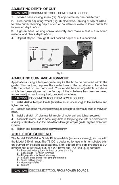
ADJUSTING DEPTH OF CUTDISCONNECT TOOL FROM POWER SOURCE.1. Loosen base locking screw (Fig. 3) approximately one-quarter turn.2. Turn depth adjusting wheel (Fig. 3) clockwise, looking at top of wheel,to raise cutter reducing depth of cut or counterclockwise to lower cutter forincreasing depth of cut.3. Tighten base locking screw securely and make a test cut in scrapmaterial and check depth of cut.4. Repeat steps 1 through 3 until desired depth of cut is achieved.LOCKINGSCREW SPRING WASHERDEPTH ADJUSTINGWHEELFig. 3ADJUSTING SUB-BASE ALIGNMENTApplications using a templet guide require the bit to be centered within theguide. This, in turn, requires the center hole in the sub-base to be in linewith the collet of the motor unit. Your model has an adjustable sub-basewhich has been aligned at the factory. If the sub-base has been removedand/or readjustment is required, proceed as follows:DISCONNECT TOOL FROM POWER SOURCE.1. Install 42054 Templet Guide (available as an accessory) to the subbase andtighten securely.2. Loosen sub-base mounting screws just enough to allow sub-base to move onbase.3. Install a straight 1 /4" diameter bit in collet of motor unit and tighten securely.4. Assemble motor unit to base, align hole in templet guide with 1 /4" diameter bitand adjust depth of cut so that bit extends through templet guide. Tighten motor unitin base.5. Tighten sub-base mounting screws securely.73100 EDGE GUIDE KITThe Model 73100 Edge Guide Kit is available (as an accessory), for use withthe Model 310 trimmer. The 73100 is designed for use with non-piloted bits,on curved or straight applications. Non-piloted bits can produce a 90°straight cut, a 10° bevel cut, or a 22° bevel cut. The kit (Fig. 4) contains:A – Base and roller guide - for flush or bevel trimmingB – Edge guide – for flush trimmingC – Edge guide – for bevel trimmingD – Straight edge guide – for straight trimmingE – Guide setting gaugeF – Mounting screwsG – WrenchDISCONNECT TOOL FROM POWER SOURCE.12