Instruction manual Double Insulated Laminate Trimmers
Instruction manual Double Insulated Laminate Trimmers
Instruction manual Double Insulated Laminate Trimmers

You also want an ePaper? Increase the reach of your titles
YUMPU automatically turns print PDFs into web optimized ePapers that Google loves.
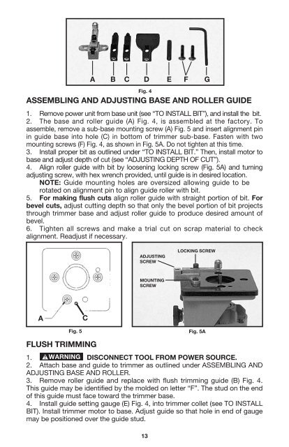
A B C D E F GFig. 4ASSEMBLING AND ADJUSTING BASE AND ROLLER GUIDE1. Remove power unit from base unit (see “TO INSTALL BIT”), and install the bit.2. The base and roller guide (A) Fig. 4, is assembled at the factory. Toassemble, remove a sub-base mounting screw (A) Fig. 5 and insert alignment pinin guide base into hole (C) in bottom of trimmer sub-base. Fasten with twomounting screws (F) Fig. 4, as shown in Fig. 5A. Do not tighten at this time.3. Install proper bit as outlined under “TO INSTALL BIT.” Then, install motor tobase and adjust depth of cut (see “ADJUSTING DEPTH OF CUT”).4. Align roller guide with bit by loosening locking screw (Fig. 5A) and turningadjusting screw, with hex wrench provided, until guide is in desired location.NOTE: Guide mounting holes are oversized allowing guide to berotated on alignment pin to align guide roller with bit.5. For making flush cuts align roller guide with straight portion of bit. Forbevel cuts, adjust cutting depth so that only the bevel portion of bit projectsthrough trimmer base and adjust roller guide to produce desired amount ofbevel.6. Tighten all screws and make a trial cut on scrap material to checkalignment. Readjust if necessary.ADJUSTINGSCREWLOCKING SCREWMOUNTINGSCREWACFig. 5FLUSH TRIMMING1. DISCONNECT TOOL FROM POWER SOURCE.2. Attach base and guide to trimmer as outlined under ASSEMBLING ANDADJUSTING BASE AND ROLLER.3. Remove roller guide and replace with flush trimming guide (B) Fig. 4.This guide may be identified by the molded on letter “F”. The stud on the endof this guide must face toward the trimmer base.4. Install guide setting gauge (E) Fig. 4, into trimmer collet (see TO INSTALLBIT). Install trimmer motor to base. Adjust guide so that hole in end of gaugemay be positioned over the guide stud.13Fig. 5A