Polyethylene Water/Sewer - JM Eagle
Polyethylene Water/Sewer - JM Eagle
Polyethylene Water/Sewer - JM Eagle
- No tags were found...

Create successful ePaper yourself
Turn your PDF publications into a flip-book with our unique Google optimized e-Paper software.
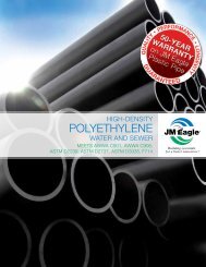
HIGH-DENSITyPOLYETHYLENEWATER/sewer PIPING SYSTEMAWWA C901, AWWA C906, ASTM D2239, ASTM D2737,ASTM D3035, F714TECHNICAL & INSTALLATION GUIDEBuilding essentialsfor a better tomorrow
HIGH-DENSITyPOLYETHYLENEWATER/sewer PIPING SYSTEMContents1.02.0INTRODUCTION. . . . . . . . . . . . . . . . . . . . . . . . . . . . . . . . . . . . . . . . 6Product and Technical Information .. . . . . . . . . . . . . . . . . . 72.1Effect of Environmental Exposure onPhysical Properties. . . . . . . . . . . . . . . . . . . . . . . . . . . . . . . 72.1.12.1.22.1.32.1.42.1.52.1.6Chemical Resistance .. . . . . . . . . . . . . . . . . . . . . . . . . 7Weather Resistance . . . . . . . . . . . . . . . . . . . . . . . . . . 8Installation Temperat.ures.. . . . . . . . . . . . . . . . . . . 8Thermal Expansion and Contraction .. . . . . . . . . . 8Effect of External Loading Stresses.. . . . . . . . . . 8Plastic Pipe Damage & Repair.. . . . . . . . . . . . . . . . . . 93.0INSTALLATION GUIDELINES. . . . . . . . . . . . . . . . . . . . . . . . . . . . . . 103.13.2Handling .. . . . . . . . . . . . . . . . . . . . . . . . . . . . . . . . . . . . . . . 10Unloading.. . . . . . . . . . . . . . . . . . . . . . . . . . . . . . . . . . . . . . . 103.2.13.2.2Unloading Site Requirements .. . . . . . . . . . . . . . . . 11Handling Equipment.. . . . . . . . . . . . . . . . . . . . . . . . . 113.33.43.53.63.7Stringing. . . . . . . . . . . . . . . . . . . . . . . . . . . . . . . . . . . . . . . . 12Dragging. . . . . . . . . . . . . . . . . . . . . . . . . . . . . . . . . . . . . . . . 13Cutting .. . . . . . . . . . . . . . . . . . . . . . . . . . . . . . . . . . . . . . . . . 13Cold-Weather Handling.. . . . . . . . . . . . . . . . . . . . . . . . . . 13Other Handling Precautions. . . . . . . . . . . . . . . . . . . . . . 14
Publications by the American Society for Testing and Materials (ASTM),American <strong>Water</strong> Works Association (AWWA) and the Plastics Pipe Institute(PPI) can also be helpful. Use of this information will minimize the potential forfailure resulting from improper design and installation practices.2.0 Product and Technical InformationThe <strong>JM</strong> <strong>Eagle</strong> Municipal & Industrial <strong>Water</strong> or <strong>Sewer</strong> Piping System is manufacturedto meet the requirements of ASTM D3035, ASTM F714, AWWAC901 or AWWA C906. Potable water pipe is listed to ANSI/NSF 14/61. Consultyour <strong>JM</strong> <strong>Eagle</strong> sales representative for advice regarding any questionsconcerning use of the <strong>JM</strong> <strong>Eagle</strong> Municipal & Industrial <strong>Water</strong> or <strong>Sewer</strong> PipingSystem.Potable water pipe is available with highly visible blue stripes OR a blueprint line.2.1 Effect of Environmental Exposure onPhysical Properties2.1.1 Chemical Resistance<strong>JM</strong> <strong>Eagle</strong> Municipal & Industrial <strong>Water</strong> or <strong>Sewer</strong> <strong>Polyethylene</strong> Pipe, for allpractical purposes, is chemically inert. There are a few chemicals that willaffect it, but it will not rot, rust or corrode by electrolytic action or requirecathodic protection. Potable water pipe should be disinfected in accordancewith ANSI/AWWA C651. Chemical solutions used for disinfecting new or repairedpotable systems should not exceed 12 percent active chlorine. Higherconcentrations can degrade polyethylene.Chemical resistance data for polyethylene pipe can be found in the PlasticPipe Institute’s (PPI) Technical Report TR-19, found at www.plasticpipe.org.HDPE WATER/SEWER PIPING SYSTEM TECHNICAL & INSTALLATION GUIDE7
2.1.2 Weather Resistance<strong>JM</strong> <strong>Eagle</strong> Municipal & Industrial <strong>Water</strong> or <strong>Sewer</strong> Pipe is protected againstdegradation caused by ultraviolet rays from direct sunlight. The polyethyleneresin contains 2 percent to 3 percent of finely divided carbon black.This provides the black color for <strong>JM</strong> <strong>Eagle</strong> Municipal & Industrial <strong>Water</strong> or<strong>Sewer</strong> Pipe. Carbon black is the most effective additive for enhancing theweathering characteristics of polyethylene pipe. <strong>JM</strong> <strong>Eagle</strong> Municipal & Industrial<strong>Water</strong> or <strong>Sewer</strong> Pipe can be safely stored outside in most climatesfor periods of many years without danger of loss of physical properties dueto ultraviolet (UV) exposure. In general, <strong>JM</strong> <strong>Eagle</strong> Co. recommends the useof a first-in first-out inventory management procedure.2.1.3 Installation Temperatures<strong>JM</strong> <strong>Eagle</strong> Municipal & Industrial <strong>Water</strong> or <strong>Sewer</strong> Pipe can be installed at anyambient temperature condition in which normal installation operations wouldcontinue. In cold weather, however, special procedural recommendations, asoutlined in this bulletin, should be followed.2.1.4 Thermal Expansion and ContractionThe coefficient of thermal expansion for <strong>JM</strong> <strong>Eagle</strong> Municipal & Industrial <strong>Water</strong>or <strong>Sewer</strong> Pipe is 9 x 10 -5 inch/inch/degrees F. This translates to an easyrule of thumb: the pipe changes in length 1 inch per 10 degrees F change intemperature per 100 feet of pipe length. The effect of expansion and contractionmust be considered when using compression and mechanical typefittings. The fitting must possess sufficient pullout resistance to counteractthe thermal stress forces generated by the pipe.2.1.5 Effect of External Loading StressesConsideration must be given to the installation of all plastic piping systems,including the <strong>JM</strong> <strong>Eagle</strong> Municipal & Industrial <strong>Water</strong> or <strong>Sewer</strong> Piping System,to avoid failures caused by excessive external stress. Field experiencehas shown that excessive externally induced stresses can act independently8 HDPE WATER/SEWER PIPING SYSTEM TECHNICAL & INSTALLATION GUIDE
or together with internal pressure to exceed material strength and causefailure. Excessive installed bending in plastic piping systems, particularly atjoints, can exceed stress limits and result in failure. Pipe where joined to fittingsshould be laid true to line and grade and backfilled carefully to preventdifferential settlement, and thus excessive bending. See “Permanent MinimumBending Radius Limits.”Excessive stresses and failure of plastic pipe can also result from impact,indentations or deflection. Avoid excessive compaction forces and particularlyavoid installation of the pipe against a source of point loading. The bedfor the pipe and fill materials around the pipe must be free of rocks, blockingmaterials or other sources of point loading or deflection. Heavy machinecompaction as by roller or hydrohammer should be used only for consolidationof final backfill with a minimum of 18 inches of previously layered andcompacted backfill.ASTM D2774, “Standard Recommended Practice for Underground Installationof Thermoplastic Pressure Piping,” provides additional information fordirect burial of <strong>JM</strong> <strong>Eagle</strong> Municipal & Industrial <strong>Water</strong> or <strong>Sewer</strong> Pipe.2.1.6 Plastic Pipe Damage & RepairIndustry surveys indicate the primary causes for repair of plastic piping arefrom third-party damage and poor workmanship in the initial installation. Repaircan be minimized by using careful mapping and location methods andby proper training and inspection procedures. Repairing PE pipe is similarto repairing ductile iron and PVC water pipe. Mechanical couplings or fusionmethods can be used for damage, such as puncture, rupture, or saddle repair.The first step in making a repair is determining the problem.For smaller sizes, an electrofusion system is useful in making repairs to polyethylenepipe.HDPE WATER/SEWER PIPING SYSTEM TECHNICAL & INSTALLATION GUIDE9
3.0 INSTALLATION GUIDELINES3.1 Handling<strong>JM</strong> <strong>Eagle</strong> Municipal & Industrial <strong>Water</strong> or <strong>Sewer</strong> Pipe is a tough flexible productthat is able to withstand normal installation handling. However, unusuallyrough handling of <strong>JM</strong> <strong>Eagle</strong> Municipal & Industrial <strong>Water</strong> or <strong>Sewer</strong> Pipe canresult in damage to the pipe wall. Care should be taken to avoid pushing or pulling<strong>JM</strong> <strong>Eagle</strong> Municipal & Industrial <strong>Water</strong> or <strong>Sewer</strong> Pipe over or around sharpprojections. <strong>JM</strong> <strong>Eagle</strong> Municipal & Industrial <strong>Water</strong> or <strong>Sewer</strong> Pipe is subjectto impact damage when dropped from excessive heights or when heavy objectsare dropped upon it, particularly during cold weather. Kinking or bucklingshould be avoided and any section of pipe that has been damaged in this mannershould be cut out. Based on pipe pressure tests, a good rule of thumb indetermining if a scratched piece of pipe should be cut out of the piping systemis: if the scratch depth is greater than 10 percent of the pipe wall thickness,then the section should be removed or repaired.3.2 UnloadingThe means by which PE Pipe is unloaded in the field is the decision andresponsibility of the customer. Preferred unloading is in units using mobilemechanical equipment such as forklifts or front-end loaders with adequateforks. Ensure that the equipment can handle the weight of thepipes (use <strong>JM</strong> <strong>Eagle</strong> catalog for book weights) and able to lift the pipebundles clear off the truck. Obtain and follow the handling instructions providedby the delivery personnel. Be extra cautious in handling pipe duringinclement weather.WARNING: Unsafe unloading and handling can result in damage to propertyor equipment, injury and death. Unloading and handling must be performedsafely. Keep unnecessary people away from the area during unloading.Only properly trained personnel should operate unloading equipment.Refer to the Plastic Pipe Institute’s Material Handling Guide for additionalguidance, available at www.plasticpipe.org/publications/material_handling_guide.html10 HDPE WATER/SEWER PIPING SYSTEM TECHNICAL & INSTALLATION GUIDE
3.2.1 Unloading Site RequirementsThe unloading site must be relatively flat and level. It must be large enoughfor the carrier’s truck, the load handling equipment and its movement, andfor temporary load storage. Silo packs and other palletized packages shouldbe unloaded from the side with a forklift. Non-palletized pipe, fittings, fabrications,manholes, tanks or other components should be unloaded withlifting equipment and wide web slings, or with a forklift.3.2.2 Handling EquipmentAppropriate unloading and handling equipment of adequate capacity mustbe used to unload the truck. Safe handling and operating procedures mustbe observed.Pipe must not be rolled or pushed off the truck. Pipe, fittings, fabrications,tanks, manholes and other components must not be pushed or dumped offthe truck, or dropped.Although polyethylene piping components are lightweight compared to similarcomponents made of metal, concrete, clay or other materials, larger componentscan be heavy. Lifting and handling equipment must have adequaterated capacity to lift and move components from the truck to temporarystorage. Equipment such as a forklift, a crane, a side boom tractor or an extensionboom crane is used for unloading. Do not use chains or wire ropes,but use fabric slings.When using a forklift, or forklift attachments on equipment such as articulatedloaders or bucket loaders, lifting capacity must be adequate at the loadcenter on the forks. Forklift equipment is rated for a maximum lifting capacityat a distance from the back of the forks. If the weight-center of the load isfarther out on the forks, lifting capacity is reduced.Before lifting or transporting the load, forks should be spread as wide apartas practical, forks should extend completely under the load, and the loadshould be as far back on the forks as possible.HDPE WATER/SEWER PIPING SYSTEM TECHNICAL & INSTALLATION GUIDE11
WARNING: During transport, a load on forks that are too short or too closetogether, or a load too far out on the forks, may become unstable and pitchforward or to the side, and result in damage to the load or property, or hazardsto people.Lifting equipment such as cranes, extension boom cranes and side boomtractors should be hooked to wide web choker slings that are secured aroundthe load or to lifting lugs on the component. Only wide web slings should beused. Do not use wire rope slings and chains for they can damage components.Spreader bars should be used when lifting pipe or components longerthan 20 feet.WARNING: Before use, inspect slings and lifting equipment. Equipment withwear or damage that impairs function or load capacity should not be used.WARNING: When breaking down bulk packs, take care to stand clear ofthe pipe while strapping is being cut. Coiled HDPE pipe may contain energyas in a spring. Uncontrolled release, i.e., cutting of straps, can result indangerous uncontrolled forces. All safety precautions and proper equipmentis required.3.3 StringingReel trailers can be helpful when stringing out coiled pipe for direct burial,plow-in, pull-in or insertion renewal. It is helpful when handling coiled pipeto string the pipe out on the ground upon arrival at the job site. This allowstime for the coil set to relax, and will simplify handling and emplacement ofthe pipe.When uncoiling pipe by hand, only cut those straps on the coils, which arenecessary to uncoil outer rolls; cut internal bands whenever necessary asthe coil is unrolled.Always inspect the pipe as it is being uncoiled and during installation to makesure no damage to the pipe has occurred during shipment and subsequenthandling at the job site.12 HDPE WATER/SEWER PIPING SYSTEM TECHNICAL & INSTALLATION GUIDE
3.4 DraggingOccasionally, when long strings of pipe are joined together, it is necessaryto drag the pipe to where it will be installed. When the pipe must be draggedover rocky terrain or hard pavement, take precautions to protect the pipefrom abrasion. Sandbags, used tires or short logs may be used to supportthe pipe and prevent hard contact with sharp rocks or hard pavement.3.5 CuttingFor smaller sizes, <strong>JM</strong> <strong>Eagle</strong> Municipal & Industrial <strong>Water</strong> or <strong>Sewer</strong> Pipeshould be cut with pipe cutters designed for plastic pipe. These tools easilyprovide the square cut ends that are necessary to provide satisfactory fusionjoints. If carpenter or hacksaws are used to cut the pipe, special care mustbe taken to ensure square cut ends and to clean the resultant sawdust frominside the pipe.WARNING: Before cutting coiled pipe, restrain both sides of cut. Pipe isunder tension. Unrestrained pipe can spring back forcibly while being cutand could cause personal injury.3.6 Cold-Weather Handling<strong>Polyethylene</strong> is a tough piping material; yet colder temperatures below 40degrees F can reduce resistance to damage from mechanical abuse, suchas impact. Avoid dropping the pipe, especially in cold weather. The recommendedmethod of unloading is to use a forklift or crane, in all cases thepipe should be inspected for damage.When handling coiled pipe at temperatures below 40 degrres F, it is helpfulto uncoil the pipe that is to be installed and let it straighten out prior tomaking the installation. This can be done by gradually uncoiling the pipe andcovering it with dirt at intervals to keep it from coiling up again. Always becareful when cutting the straps on coils of pipe because the outside end ofa coil may spring out when the strapping is removed.HDPE WATER/SEWER PIPING SYSTEM TECHNICAL & INSTALLATION GUIDE13
In cold-weather conditions, more effort will be required to uncoil the pipeand piping will spring back more forcibly if the ends are not anchored or restrained.Carefully follow equipment manufacturer’s recommendations andguidelines for cold-weather conditions.3.7 Other Handling PrecautionsDuring the transport of pipe, it should be continuously supported in a mannerso as to minimize movement between the pipe and its support. Anypractice of carrying supplies or equipment on top of plastic pipe should beavoided because of damage from sharp edges and other projections.Care should be taken to protect the pipe from excessive heat. Be particularlycareful of open flames. Do not lay an open flame or torch across pipe surfaces.3.8 TrenchingFor direct burial of <strong>JM</strong> <strong>Eagle</strong> Municipal & Industrial <strong>Water</strong> or <strong>Sewer</strong> Pipe,trench bottoms should be relatively smooth, continuous and free of rocksand other debris. When ledge rock, hardpan or boulders are encountered,the bottom of the trench should be padded with sand or other fine-grainedfill materials. The trench should be wide enough to allow (a) fusion in theditch if required, (b) snaking of the pipe along the bottom of the trench ifneeded, and (c) filling and compaction of sidewalls. Minimum trench widthscan be utilized in most instances by joining the pipe before lowering it intothe trench. Refer to ASTM D2321, “Standard Practice for Underground Installationof Thermoplastic Pipe for <strong>Sewer</strong>s and Other Gravity Flow Applications”and ASTM D2774 “Standard Practice for Underground Installation ofThermoplastic Pressure Piping” for additional information.Generally, sufficient cover must be maintained to provide reasonable protectionagainst anticipated external stress loads. Where frost penetration andsurface loads need not be considered, a minimum depth to provide 18 inchesof cover above the pipe is recommended. When surface loads are expected,a minimum of 3 feet of cover is recommended. Where frost is a factor, pipeshould be buried 6 inches below greatest recorded frost penetration.14 HDPE WATER/SEWER PIPING SYSTEM TECHNICAL & INSTALLATION GUIDE
3.9 Pipe Placement in Trenches<strong>JM</strong> <strong>Eagle</strong> Municipal & Industrial <strong>Water</strong> or <strong>Sewer</strong> Pipe can be joined eitherabove ground or in the ditch as the situation dictates. Though most joiningcan be accomplished above ground, joining that must be done in the ditchshould be well planned to ensure that enough space is available and thatproper alignment is achieved. Care should be taken to avoid buckling, gouging,and other mechanical damage when lowering <strong>JM</strong> <strong>Eagle</strong> Municipal &Industrial <strong>Water</strong> or <strong>Sewer</strong> Pipe into the ditch.Align all pipe true to line and grade. As mentioned earlier, extremely coldweather makes <strong>JM</strong> <strong>Eagle</strong> Municipal & Industrial <strong>Water</strong> or <strong>Sewer</strong> Pipe stifferand increases the likelihood of impact damage. When an unstable trenchbottom is encountered and, in the opinion of the engineer, it cannot supportthe pipe, an additional depth should be excavated and refilled to pipe gradewith material approved by the engineer.Because plastic pipe contracts as it cools, it is desirable in warm weather tosnake the pipe in the bottom of the trench. This provides for “slack” in the pipelineto be taken up as the pipe cools and contracts in the ditch prior to backfilling.3.10 Backfilling & CompactionBackfilling and compaction of installed <strong>JM</strong> <strong>Eagle</strong> Municipal & Industrial <strong>Water</strong>or <strong>Sewer</strong> Pipe must be accomplished so as to avoid induced bendingstresses both as a result of the backfilling itself and from differential settlingof fill materials subsequent to the backfilling operation. Additionally, careshould be taken to avoid mechanical damage to the pipe from the fill materialitself. Attention to careful emplacement, filling and compaction procedureswill prevent such induced stresses and mechanical damage.<strong>JM</strong> <strong>Eagle</strong> Municipal & Industrial <strong>Water</strong> or <strong>Sewer</strong> Pipe installations should becontinuously supported beneath their entire lengths by clean and firm backfillmaterials (no rocks). Intermittent blocking should not be used to supportpipe-excavated sections.Relatively compactable and clean fill materials should be used to bed newlyinstalled pipe with particular attention to filling voids beneath transitionHDPE WATER/SEWER PIPING SYSTEM TECHNICAL & INSTALLATION GUIDE15
connections. Side-fill compaction should be utilized to develop lateral passivesoil forces when backfilling larger diameter thin wall pipes. The first layerof fill material around and about 12 inches over the pipe should be free fromrocks or frozen chunks, which could damage the pipe. This layer should bewell compacted by hand. Successive layers should be spread uniformly to fillthe trench completely. Large rocks, frozen earth and decomposable debrissuch as wood should not be included in the backfill. The maximum fill materialparticle size versus the pipe size is given in the following table.Maximum Particle Size vs. Pipe SizeNOMINAL PIPE SIZE (inches) Maximum Particle Size2 to 4 ½6 to 8 ¾10 to 15 116 and larger 1½Table 1Heavy rollers and large mechanical tampers such as hydrohammers shouldonly be used to consolidate the final backfill and even then there should be aminimum of 24 inches of layered and previously compacted cover.Minimum Cold (field) Bending Radius (long-term)Reference: PE Pipe – Design and Installation M55 AWWAPIPE DRMinimum Cold Bending Radius9 20 times pipe OD9-13.5 25 times pipe OD13.5-21 27 times pipe OD21 30 times pipe ODFittings or flange presentor to be installed in bend *100 times pipe ODTable 2* Observe the minimum cold bending radius for a distance of about 5 times the pipediameter on either side of the fitting location.Tighter bends down to 10 times the pipe diameter can be made if they aretemporary, such as in the plowing or the insertion method of installation.16 HDPE WATER/SEWER PIPING SYSTEM TECHNICAL & INSTALLATION GUIDE
4.0 TESTING4.1 Leak TestingThe intent of leak testing is to find unacceptable faults in a piping system.If such faults exist, they may manifest themselves by leakage or rupture.Leakage tests may be performed if required in the contract specifications. Testingmay be conducted in various ways. Internal pressure testing involves fillingthe test section with a nonflammable liquid or gas, then pressurizing themedium. Hydrostatic pressure testing with water is the preferred andrecommended method. Other test procedures may involve paired internal orend plugs to pressure test individual joints or sections, or an initial service test.Joints may be exposed to allow inspection for leakage. Liquids such as waterare preferred as the test medium because less energy is released if the testsection fails catastrophically. During a pressure test, energy (internal pressure)is applied to stress the test section. If the test medium is a compressiblegas, then the gas is compressed and absorbs energy while applyingstress to the pipeline. If a catastrophic failure occurs, both the pipeline stressenergy and the gas compression energy are suddenly released. However,with an incompressible liquid such as water as the test medium, the energyrelease is only the energy required to stress the pipeline.WARNING: Pressure Pipe system testing is performed to discover unacceptablefaults in a piping system. Pressure testing may cause such faultsto fail by leaking or rupturing. This may result in catastrophic failure. Pipingsystem rupture may result in sudden, forcible, uncontrolled movement ofsystem piping or components, or parts of components.WARNING: Pipe Restraint. The pipe system under test and any closures in thetest section should be restrained against sudden uncontrolled movement fromcatastrophic failure. Test equipment should be examined before pressure is appliedto insure that it is tightly connected. All low-pressure filling lines and otheritems not subject to the test pressure should be disconnected or isolated.WARNING: Personal Protection. Take suitable precautions to eliminate hazardsto personnel near lines being tested. Keep all personnel a safe distanceaway from the test section during testing.HDPE WATER/SEWER PIPING SYSTEM TECHNICAL & INSTALLATION GUIDE17
REFERENCE: ASTM F2164, “Standard Practice for Field Leak Testing of<strong>Polyethylene</strong> (PE) Pressure Piping System Using Hydrostatic Pressure.”4.2 Pressure Testing PrecautionsThe piping section under test and any closures in the test section should berestrained or otherwise restricted against sudden uncontrolled movement inthe event of rupture. Expansion joints and expansion compensators shouldbe temporarily restrained, isolated or removed during the pressure test.Testing may be conducted on the system, or in sections. The limiting testsection size is determined by test equipment capability. If the pressurizingequipment is too small, it may not be possible to complete the test within allowabletesting time limits. If so, higher capacity test equipment, or a smallertest section may be necessary.If possible, test medium and test section temperatures should be lessthan 100 degrees F (38 degrees C). At temperatures above 100 degrees F(38 degrees C), reduced test pressure is required. Before applying testpressure, time may be required for the test medium and the test sectionto temperature equalize.4.3 ReferencesThe following reference publications provide pressure testing information:ASME B31.1 Power Piping, Section 137, Pressure Tests.Plastics Pipe Institute, Handbook of <strong>Polyethylene</strong> Pipes, Dallas, Texas.ASTM F1417, Standard Test Method for Installation Acceptance of PlasticGravity <strong>Sewer</strong> Lines Using Low-Pressure Air.Uni-Bell ® PVC Pipe Association Publication, Uni-B-6-98, “RecommendedPractice for Low-Pressure Air Testing of Installed <strong>Sewer</strong> Pipe.”ASTM F2164, “Standard Practice for Field Leak Testing of <strong>Polyethylene</strong> (PE)Pressure Piping System Using Hydrostatic Pressure.”18 HDPE WATER/SEWER PIPING SYSTEM TECHNICAL & INSTALLATION GUIDE
Other pressure testing procedures may or may not be applicable dependingupon piping products and/or piping applications.4.4 Test PressureTest pressure may be limited by valves, or other devices, or lower pressurerated components. Such components may not be able to withstand the requiredtest pressure, and should be either removed from, or isolated from thesection being tested to avoid possible damage to, or failure of these devices.Isolated equipment should be vented.• For continuous pressure systems where test pressure limiting componentsor devices have been isolated or removed, or are not present in thetest section, the maximum allowable test pressure is 1.5 times the systemdesign pressure at the lowest elevation in the section under test.• If the test pressure limiting device or component cannot be removed orisolated, then the limiting section or system test pressure is the maximumallowable test pressure for that device or component.4.5 Test DurationFor any test pressure from 1.0 to 1.5 times the system design pressure, thetotal test time including initial pressurization, initial expansion, and time attest pressure, must not exceed 8 hours. If the pressure test is not completeddue to leakage, equipment failure, etc., the test section should be de-pressurized,and allowed to “relax” for at least 8 hours before bringing the testsection up to test pressure again.4.6 Pre-Test InspectionTest equipment and the pipeline should be examined before pressure is appliedto ensure that connections are tight, necessary restraints are in placeand secure, and components that should be isolated or disconnected areisolated or disconnected. All low-pressure filling lines and other items notsubject to the test pressure should be disconnected or isolated.HDPE WATER/SEWER PIPING SYSTEM TECHNICAL & INSTALLATION GUIDE19
4.7 Relieving Air from PipelineAIR SHOULD BE VENTED FROM ALL HIGH SPOTS IN THE PIPELINE BE-FORE MAKING EITHER PRESSURE OR LEAKAGE TESTS. AUTOMATICAIR RELEASE VALVES ARE RECOMMENDED. Compressed entrapped aircauses difficulty in pumping to required pressure for strength tests. Furthermore,a pipeline may leak compressed air when it is actually water tight, andif this occurs during a leakage test it will cause erroneous results.4.8 Hydrostatic testingHYDROSTATIC PRESSURE TESTING IS PREFERRED AND IS STRONGLYRECOMMENDED. The preferred testing medium is clean water. The test sectionshould be completely filled with the test medium, taking care to bleed offany trapped air. Venting at high points may be required to purge air pocketswhile the test section is filling. Venting may be provided by loosening flanges,or by using equipment vents. Re-tighten any loosened flanges before applyingtest pressure.4.9 Pneumatic TestingWARNING: Pressure compressed air or any pressurized gas used as a testmedium may present severe hazards to personnel in the vicinity of lines beingtested. Extra personnel protection precautions should be observed whena gas under pressure is used as the test medium.WARNING: Explosive Failure. Piping system rupture during pneumatic pressuretesting may result in the explosive, uncontrolled movement of systempiping, components, or parts of components. Keep personnel a safe distanceaway from the test section during testing.Pneumatic testing should not be used unless the owner and the responsibleproject engineer specify pneumatic testing or approve its use as analternative to hydrostatic testing. Pneumatic testing (testing with a gas underpressure) should not be considered unless one of the following conditionsexists:20 HDPE WATER/SEWER PIPING SYSTEM TECHNICAL & INSTALLATION GUIDE
• The piping system is so designed that it cannot be filled with a liquid.• The piping system service cannot tolerate traces of liquid testing medium.The testing medium should be non-flammable and non-toxic. The test pressureshould not exceed the maximum allowable test pressure for any nonisolatedcomponent in the test section.Leaks may be detected using mild soap solutions (strong detergent solutionsshould be avoided), or other non-deleterious leak detecting fluids applied tothe joint. Bubbles indicate leakage. After leak testing, all soap solutions orleak detecting fluids should be rinsed off the system with clean water.4.10 High-Pressure ProcedureFor continuous pressure rated pipe systems, the pressure in the test sectionshould be gradually increased to not more than one-half of the testpressure, then increased in small increments until the required test pressureis reached. Test pressure should be maintained for 10 to 60 minutes, thenreduced to the design pressure rating, and maintained for such time as requiredto examine the system for leaks.4.11 Low-Pressure ProcedureFor components rated for low pressure service the specified rated test pressureshould be maintained for 10 minutes to one hour, but not more than onehour. Test pressure ratings must not be exceeded. Leakage inspectionsmay be performed during this time. If the test pressure remains steady(within 5 percent of the target value) for the one-hour test time, no leakageis indicated. Pressure testing of gravity-flow sewer lines should be conductedin accordance with ASTM F1417, Standard Test Method for InstallationAcceptance of Plastic Gravity <strong>Sewer</strong> Lines Using Low-Pressure Air.HDPE WATER/SEWER PIPING SYSTEM TECHNICAL & INSTALLATION GUIDE21
4.12 Initial Service TestingAn initial service test may be acceptable when other types of tests are notpractical, where leak tightness can be demonstrated by normal service, orwhen initial service tests of other equipment are performed. An initial servicetest may apply to systems where isolation or temporary closures are impractical,or where checking out pumps and other equipment affords the opportunityto examine the system for leakage prior to full-scale operations.4.13 Test ProcedureThe piping system should be gradually brought up to normal operatingpressure, and held at operating pressure for at least 10 minutes. Duringthis time, joints and connections should be examined for visual evidenceof leakage.4.14 Non-Testable SystemsSome systems may not be suitable for pressure testing. These systems maycontain non-isolatable components, or temporary closures may not be practical.Such systems should be carefully inspected during and after installation.Inspections such as visual examination of joint appearance, mechanicalchecks of bolt or joint tightness, and other relevant examinations shouldbe performed.5.0 REPAIRS TO DAMAGED PIPERepair situations may arise if a polyethylene pipe has been damaged. Damagemay occur during shipping and handling, during installation, or afterinstallation. Damage may include scrapes or abrasions, breaks, punctures,kinks, or emergency squeeze-off. Permanent repair usually involves removingand replacing the damaged pipe or fitting. In some cases, temporaryrepairs may restore sufficient serviceability and allow time to schedule permanentrepairs in the near future. IN ANY EVENT, ALL DAMAGED MATERIALMAY BE REPLACED OR REPAIRED BY METHODS AUTHORIZED BY THE22 HDPE WATER/SEWER PIPING SYSTEM TECHNICAL & INSTALLATION GUIDE
ENGINEER.5.1 Damage AssessmentDamaged pipe or fittings should be inspected and evaluated. Pipe, fittings,fabrications or structures with excessive damage should not be installed.Damage that occurs after installation may require that the damaged pipe orcomponent be removed and replaced.WARNING: Scrapes or gouges in pressure pipe cannot be repaired by fillingin with extrusion or hot air welding. The damaged sectionshould be removed and replaced.WARNING: Improperly made fusion joints cannot be repaired.Improper butt fusions must be cut out and re-done from the beginning.Poorly joined socket or electrofusion fittings must be removed and replaced.Poorly joined saddle fittings must be removed by cutting out the main pipesection, or, if the main is undamaged, made unusable by cutting the branchoutlet or chimney off the saddle fitting, and installing a new saddle fitting ona new section of main.WARNING: Broken or damaged fittings cannot be repaired and, as such,should be removed and replaced.WARNING: Kinked pipe must not be installed and cannot be repaired. Itmust be removed and replaced.WARNING: Pipe damaged during an emergency squeeze-off cannotbe repaired. Squeeze-off damaged pipe must be removedand replaced.HDPE WATER/SEWER PIPING SYSTEM TECHNICAL & INSTALLATION GUIDE23
Safety and Field Precautions:1. WARNING: Treat electrical tools as potential sources of ignition andfollow standard safety procedures for working in explosiveatmospheres.2. WARNING: Only properly trained and qualified personnel should makefusions.3. WARNING: Wear suitable gloves and eye protection.4. WARNING: Temperature of fusion tools should be checked to be surethat they conform to the recommended operating temperaturerange.5. WARNING: When breaking down bulk packs, take care to stand clearof pipe while strapping is being cut. Coiled HDPE pipe maycontain energy as in a spring. Both the straps and the pipemay spring outward when the strap is cut and could causesevere injury. All safety precautions and proper equipmentis required.6. WARNING: Before cutting coiled pipe, restrain both sides of cut. Pipeis under tension. Unrestrained pipe can spring back forciblywhile being cut and could cause personal injury.7. WARNING: Understand and follow all equipment manufacturer’s recommendationsand guidelines.8. WARNING: Properly made heat fusion joints do not leak. An improperlymade joint that leaks when pressurized may precede acatastrophic event that may result in violent or dangerouspipe movement, a sudden release of the system’s pressurizedcontents, and the potential for personal injury. All faultyjoints must be cut out and replaced using approved fusionprocedures, after the system has been safely depressurized.Stay clear of leaking, faulty joints until the system hasbeen fully depressurized.24 HDPE WATER/SEWER PIPING SYSTEM TECHNICAL & INSTALLATION GUIDE
5.2 Heating Tool MaintenanceClean heater adaptors carefully before and after each fusion. Remove anyresidual polyethylene using a clean non-synthetic cloth. Never use metalobjects to clean heater adaptors because they can damage the surface.The heating tool temperature recommendations shown in this bulletin representthe temperature on the surface of the heater adaptors that actuallycontact the pipe or fitting. This temperature should be monitored daily toensure compliance with recommendations.The operator can usually expect the tool thermometer to indicate a highertemperature than specified in order to achieve the correct surface temperature.In addition, the operator will normally encounter variations in heateradaptor temperature due to different adaptor configurations. In these cases,the adaptor having the lower temperature should be set at the recommendedtemperature.6.0 FUSION PROCEDURES6.1 SOCKET FUSIONWARNING: Understand and follow all equipment manufacturers’ recommendationsand guidelines.Equipment:1. Pipe or tubing cutter2. Cold ring3. Depth gauge4. Chamfering tool5. Heating tool6. Female and male heater adaptors7. Fitting puller8. Clean non-synthetic clothHDPE WATER/SEWER PIPING SYSTEM TECHNICAL & INSTALLATION GUIDE25
Procedures:1. Cut the pipe squarely with a pipe or tubing cutter.2. Chamfer pipe using a chamfering tool.3. Clean the end of the pipe with a clean, non-synthetic cloth.4. Install the depth gauge and cold ring. Remove depth gauge oncecold ring is secured. Ensure pipe is sufficiently round once cold ringis installed.5. Place a fitting puller on couplings, caps and reducers on 2-inch IPSthrough 4-inch IPS.6. Check the heater adaptor faces for proper joining temperature 500degrees F (± 10 degrees F).7. Place the fitting on the tool and then the tool on the pipe. Push thetool, pipe and fitting together with even pressure.8. When the fitting is against the tool and the tool against the cold ring,begin the heating cycle shown in Table 3.9. When you have heated for the proper cycle time, remove the fittingfrom the tool with a quick snap action. Then remove the tool fromthe pipe in the same way.10. Quickly inspect the melt pattern on the pipe and fitting. If an incompletepattern is obtained, repeat steps 1-9 using a longer heatingcycle and new fitting.11. Within 3 seconds, carefully line up and push the fitting onto the pipeuntil it bottoms against the cold ring on the pipe. Do not twist orrotate the fitting.12. Hold the joint firmly together without movement for the recommendedholding time shown in table below. After an additional 3minutes, release the cold ring and fitting puller.13. Inspect the entire circumference of the fused joint to be sure thereare no open gaps in the pipe to fitting juncture, and that the melt ispressed against the coupling all the way around. If a gap is found orthe joint is not aligned properly, cut it out and repeat the procedure.See Figure A for a properly made socket fusion joint. Only acceptjoints that meet these requirements. Never allow a questionablejoint to be installed.14. Wait an additional 10 minutes prior to pressure testing or burial.26 HDPE WATER/SEWER PIPING SYSTEM TECHNICAL & INSTALLATION GUIDE
Table 3Pipe SizeSocket Fusion Time CyclesHeating Time(sec)Holding Time(sec)¾" IPS 12 301" IPS 15 401¼" IPS 18 401½" IPS 20 402" IPS 24 403" IPS 28 504" IPS 32 50Figure ACorrectly Made Socket Fusion JointCold Weather Considerations (Below 55°F):• Carefully remove (by light tapping or scraping) the ice and frost fromthe fusion areas and the areas to be clamped. Otherwise, ice will meltwhen exposed to the heating tool and spot chill the polyethylene. Thiscould cause incomplete fusion.• If possible, store fittings at room temperature (such as in truck cab)prior to use. This will reduce fitting contraction and make placing fittingon heater adaptor easier.HDPE WATER/SEWER PIPING SYSTEM TECHNICAL & INSTALLATION GUIDE27
• Cold weather also causes pipe contraction that can result in a loose orslipping cold ring. For best results, clamp one cold ring in its normal positionbehind the depth gauge. Place shim material (i.e., a piece of paperor rag) around the inside diameter of a second cold ring and clampthis cold ring directly behind the first cold ring to prevent slippage.• Shield the heating tool and fusion area from the wind, snow and freezingrain.• Ensure heater adaptor faces maintain a temperature of 500 degrees F(±10 degrees F).• The length of cycle necessary to obtain a complete melt patternwill depend not only on the outdoor temperature, but also on windconditions, pipe contraction and operator technique. The maximumheating cycle times shown in Table 4 should be used as a startingpoint for determining the exact heating cycle time for the particularinstallation conditions.Determining the exact heating cycle time can be accomplished by makinga test melt pattern on a piece of cold scrap pipe. If the initial melt pattern isincomplete, try a 5-second longer cycle on another cold piece of scrap pipe.Continue this process until a complete melt pattern is obtained. Avoid cyclesin excess of that required to achieve a good melt pattern.Once the optimum heating cycle is established, begin fusion by placing thefemale adaptor on the pipe. Start counting the heating cycle once the pipeis completely seated. The socket fitting should then be pushed on the maleadaptor. There should be no problem with melt development in the fittingsince the fit will be snug.Work quickly once pipe and fitting have been removed from the heating toolso that melt heat loss is minimized. But still take time (2-3 seconds) to inspectboth melt patterns.WARNING: Understand and follow all equipment manufacturer’s recommendationsand guidelines.28 HDPE WATER/SEWER PIPING SYSTEM TECHNICAL & INSTALLATION GUIDE
6.2 Butt Fusion: Reference PPI’s TR-33 Generic ButtFusion Procedure for Field Joining of PE PipeThe most widely used method for joining individual lengths of large diameterpolyethylene pipe is by heat fusion of the pipe butt ends, as illustrated inFigure B. This technique, which precludes the need for specially modifiedpipe ends or couplings, produces a permanent, economical and flow-efficientconnection. Field-site butt fusions may be made readily by trainedoperators using specially developed butt fusion machines that secure andprecisely align the pipe ends for the fusion process.Heater Surface temperature 400-450 degrees F (204-232 degrees C)Interfacial Pressure60-90 psi (4.14-6.21 bar)The six steps involved in making a butt fusion joint are:1. Securely fasten the components to be joined2. Face the pipe ends3. Align the pipe profile4. Melt the pipe interfaces5. Join the two profiles together6. Hold under pressureFigure BCorrectly Made Butt Fusion JointHDPE WATER/SEWER PIPING SYSTEM TECHNICAL & INSTALLATION GUIDE29
6.2.1 SecureEach component that is to be fused must be held in position so that it will notmove unless it is moved by the clamping device.6.2.2 FaceThe pipe ends must be faced to establish clean, parallel mating surfaces.Most, if not all, equipment manufacturers have incorporated the rotatingplaner block design in their facers to accomplish this goal. Facing is continueduntil a minimal distance exists between the fixed and movable jaws ofthe machine and the facer is locked firmly and squarely between the jaws.This operation provides for a perfectly square face, perpendicular to the pipecenterline on each pipe end and with no detectable gap.6.2.3 AlignThe pipe profiles must be rounded and aligned with each other to minimizemismatch (high-low) of the pipe walls. This can be accomplished by adjustingthe clamping jaws until the outside diameters of the pipe ends match. Thejaws must not be loosened or the pipe may slip during fusion. The minimaldistance requirement between fixed and moveable jaws mentioned above allowsthe pipe to be rounded as close as possible to the joint area. The closerto the joint area that the pipe can be clamped, the better control the operatorhas in properly aligning the pipe.6.2.4 MeltHeating tools that simultaneously heat both pipe ends are used to accomplishthis operation. These heating tools are normally furnished withthermometers to measure internal heater temperature so the operator canmonitor the temperature before each joint is made. However, the thermometercan be used only as a general indicator because there is some heatloss from internal to external surfaces, depending on factors such as ambienttemperatures and wind conditions. A pyrometer or other surface-tem-30 HDPE WATER/SEWER PIPING SYSTEM TECHNICAL & INSTALLATION GUIDE
perature-measuring device should be used periodically to insure propertemperature of the heating tool face. Additionally, heating tools are usuallyequipped with suspension and alignment guides that center them on thepipe ends. The heater faces that come into contact with the pipe should beclean, oil-free and coated with a nonstick coating as recommended by themanufacturer to prevent molten plastic from sticking to the heater surfaces.Remaining molten plastic can interfere with fusion quality and must be removedaccording to the tool manufacturer’s instructions.Plug in the heater and bring the surface temperatures up to the temperaturerange (400-450 degrees F) (204-232 degrees C). Install the heater in the butt fusionmachine and bring the pipe ends into full contact with the heater. To ensurethat full and proper contact is made between the pipe ends and the heater, theinitial contact should be under moderate pressure. After holding the pressurevery briefly, it should be released without breaking contact. Continue to hold thecomponents in place, without force, while a bead of molten polyethylene developsbetween the heater and the pipe ends. When the proper bead size (seeTable 4) is formed against the heater surfaces, the heater should be removed.Bead Size for Pipe SizesPipe SizeSuggested Bead Size1¼" and smaller 1/32" – 1 /16"1¼" – 3" 1/16"3" – 8" 1/8" – 3 /16"8" – 12" 3/16" – ¼"12" – 24" ¼" – 7 /16"24" – 36" 7/16"36" – 63" 9/16"Table 46.2.5 JoiningAfter the pipe ends have been heated for the proper time, the heater tool isremoved and the molten pipe ends are brought together with sufficient forceto form a double rollback bead against the pipe wall. The fusion force isdetermined by multiplying the interfacial pressure, 60-90 psi (4.14-6.21 bar),HDPE WATER/SEWER PIPING SYSTEM TECHNICAL & INSTALLATION GUIDE31
y the pipe area.For manually operated fusion machines, a torque wrench may be used toaccurately apply the proper force. For manual machines without force readingcapability of a torque wrench, the correct fusion joining force is the forcerequired to roll the melt beads over to the pipe surface during joining. Forhydraulically operated fusion machines, the fusion force can be divided bythe total effective piston area of the carriage cylinders to give a hydraulicgauge reading in psi. The gauge reading is theoretical; the internal and externaldrag need to be added to this figure to obtain the actual fusion pressurerequired by the machine.6.2.6 HoldThe molten joint must be held immobile under pressure until cooled adequatelyto develop strength. The designs of the machines vary from a leverarm-assistto manual or automatic locking devices that assist the operatorto accomplish this step. The proper cooling time is until the joint is coolto the touch. Allowing proper times under pressure for cooling prior to removalfrom the clamps of the machine is important in achieving joint integrity.Do not apply water, wet cloths or similar items to shorten cool time. Thepulling, installation or rough handling of the pipe should be avoided for anadditional 30 minutes.6.2.7 Visual InspectionVisually inspect and compare the joint against a properly made joint. Visually,the width of butt fusion beads should be approximately two to two andone-half times the bead height above the pipe and the beads should berounded and uniformly sized all around the pipe circumference. The v-groovebetween the beads should not be deeper than half the bead height above thepipe surface. When butt fusing to molded fittings, the fitting-side bead maydisplay shape irregularities such as minor indentations, deflections and nonuniformbead rollover from molded part cooling and knit lines. In such cases,visual evaluation is based mainly on the size and shape of the pipe-sidebead. Visually unacceptable joints should be cut out and re-fused using thecorrect procedure.32 HDPE WATER/SEWER PIPING SYSTEM TECHNICAL & INSTALLATION GUIDE
Visually mitered (angled, off-set) joints should be cut out and re-fused.Coiled pipe is available in sizes through 6-inch IPS. Coiling may leave a curvaturein some pipe sizes that must be addressed in the preparation of thebutt fusion process. There are several methods to address this situation:Straighten and re-round coiled pipe before the butt fusion process. ASTMD2513 requires field re-rounding of coiled pipe larger than 3-inch IPS.If there is still curvature present, if possible, install the pipe ends in the machinein an “S” configuration with print lines approximately 180 degrees apartin order to help gain proper alignment and help produce a straight joint.If curvature is still present, another option is to install a straight piece of pipebetween the two coiled pipes.Every effort should be made to make the joint perpendicular to the axis ofthe pipe.WARNING: Understand and follow all equipment manufacturer’s recommendationsand guidelines.6.2.8 Saddle Fusion Joining Procedure of <strong>Polyethylene</strong>(PE) Pipe Mains 1.25-inch IPS and LargerThis procedure is for use only in conjunction with PPI’s Technical ReportTR-41, which more fully explains the background, scope and purposes of thePPI generic saddle fusion procedure, resuting in Figure C. This procedurehas not been qualified for use with any particular piping product or any combinationof piping products and must be qualified for use in accordance withDOT 49 CFR Part 192.283 prior to its use in field joining of PE gas pipe.Figure CHDPE WATER/SEWER PIPING SYSTEM TECHNICAL & INSTALLATION GUIDE33
Standard Saddle/Sidewall Fusion JointThis procedure can be used for HDPE pipe and fittings that have a gradedesignation (in accordance with ASTM D3350) of PE 3408/3608/4710. Thepipe and fitting nominal melt index range would be .07-.20 g/10 min. Thisprocedure is intended only as a guide because heating times can varyunder different ambient conditions. Please refer to table below for saddlefusion parameters.Generic Saddle Fusion ParametersHeater Adapter Surface TemperatureInitial Interfacial PressureHeat Soak Interfacial PressureFusion Interfacial PressureTotal Heating Time on Main – 1¼-inch IPSPressure MainTotal Heating Time on Main – 2-inch IPSPressure MainTotal Heating Time on non-pressure 1¼"IPS, 2-inch IPS mains, and on pressure ornon-pressure 3-inch IPS and larger mains.500°±10°F60±6 psi0 psi30±3 psi15 seconds max.25-35 seconds max.Look for a 1 /16-inch beadaround thefitting base.Table 5Note: Look in the lower right hand corner of the fitting label for the forces required forthat fitting (Initial Heat Force / Heat Soak Force / Fusion Force) (example 180/0/90)6.2.9 DefinitionsInitial Heat (Bead-up)—The heating step used to develop an initial meltbead on the main pipe.Initial Heat Force (Bead-up force)—The force (pounds) applied to establishan initial melt pattern on the main pipe. The Initial Heat Force is determinedby multiplying the fitting base area (square inches) by the initialinterfacial pressure (pounds per square inch).34 HDPE WATER/SEWER PIPING SYSTEM TECHNICAL & INSTALLATION GUIDE
Heat Soak Force—The force (pounds) applied after an initial melt patternis established on the main pipe. The Heat Soak Force is the minimum force(essentially 0 pounds) that ensures that the fitting, heater and main stay incontact with each other.Fusion Force—The force (pounds) applied to establish the fusion bond betweenthe fitting and the pipe. The Fusion Force is determined by multiplyingthe fitting base area (square inches) by the fusion interfacial pressure(pounds per square inch).Total Heat Time—A time that starts when the heater is placed on the mainpipe and initial heat force is applied and ends when the heater is removed.Cool Time—The time required to cool the joint to approximately 120 degrees F(49 degrees C). The fusion force must be maintained for 5 minutes on 1 ¼-inchIPS or 10 minutes for all other main sizes, after which the saddle fusion equipmentcan be removed. The joint must be allowed to cool undisturbed for anadditional 30 minutes before tapping the main or joining to the branch outlet.Interfacial Area for rectangular base fittings—The major width times themajor length of the saddle base, without taking into account the curvature ofthe base or sides, minus the area of the hole in the center of the base.Interfacial Area for round base fittings—The radius of the saddle basesquared times (3.1416), without taking into account the curvature of thebase or sides, minus the area of the hole in the center of the base.Fitting Label—The initial heat force, heat soak force and the fusion force willbe listed in the lower right-hand corner of the fitting label for all saddle fusionfittings. This will eliminate the need to calculate the fusion forces in the field.(example: 180/0/90)6.2.10 PreparationThis procedure requires the use of a saddle fusion tool. This tool must becapable of holding and supporting the main, rounding the main for goodalignment between the pipe and fitting, holding the fitting, and applying andHDPE WATER/SEWER PIPING SYSTEM TECHNICAL & INSTALLATION GUIDE35
indicating the proper force during the fusion process.1. Install the saddle fusion tool on the main according to the manufacturer’sinstructions. The tool should be centered over a clean, dry locationwhere the fitting will be fused. Secure the tool to the main. A mainbolster or support is recommended under the pipe on 6-inch IPS andsmaller main pipe sizes.2. Abrade the main, where the fitting will be joined, with a 50- to60-grit utility cloth until a thin layer of the pipe surface is removed. Theabraded area must be larger than the area covered by the fitting base.After abrading, brush residue away with a clean, dry cloth.3. Abrade the fusion surface of the fitting with 50- to 60-grit utility cloth;remove all dust and residue. Insert the fitting in the saddle fusion toolloosely. Using the saddle fusion tool, move the fitting base against themain pipe and apply about 100-pound force to seat the fitting. Securethe fitting in the saddle fusion tool.6.2.11 Heating1. The heater must be fitted with the correct heater adapters. The temperatureof the heater adapter fusion surfaces must be 490 to 510degrees F.2. Place the heating tool on the main centered beneath the fitting base.Immediately move the fitting against the heater faces, apply the initialheat force (see fitting label), and start the heat time. Apply the initial heatforce until melt is first observed on the crown of the pipe main (initialheat is the term used to describe the initial heating (bead-up) step todevelop a melt bead on the main pipe and usually is 3 to 5 seconds) andthen reduce the force to the heat soak force (Bead-up force) (see fittinglabel). Maintain the heat soak force until the total heat time is complete.3. At the end of the Total Heat Time, remove the fitting from the heaterand the heater from the main with a quick snapping action. Quicklycheck for an even melt pattern on the pipe main and fitting heatedsurfaces (no unheated areas).4. Total Heat Time ends:a. When the Total Heating Time expires for a pressurized 1¼-inch IPS or2-inch IPS main, orb. When a melt bead of about 1/16-inch is visible all around the fitting basefor a 1¼-inch IPS or 2-inch IPS non-pressurized main, or a larger pres-36 HDPE WATER/SEWER PIPING SYSTEM TECHNICAL & INSTALLATION GUIDE
surized or non-pressurized main.6.2.12 Fusion and Cooling1. Whether or not the melt patterns are satisfactory, press the fittingonto the main pipe very quickly (within 3 seconds) after removing theheater and apply the Fusion Force (see the fitting label). Maintain theFusion Force on the assembly for 5 minutes on 1¼-inch IPS and for 10minutes on all larger sizes, after which the saddle fusion equipmentmay be removed. (Fusion force adjustment may be required duringcool time, but never reduce the fusion force during cooling.)2. Cool the assembly for an additional 30 minutes before rough handlingor tapping the main. (If step 7 melt patterns were not satisfactory orif the fusion bead is unacceptable, cut off the saddle fitting above thebase to prevent use, relocate to a new section of main, and make anew saddle fusion using a new fitting.)These procedures are based on tests conducted under controlled ambienttemperature conditions. Environmental conditions on a job site couldaffect heating and cooling times. Regardless of job site conditions or ambienttemperature, the prescribed heating tool temperature is required. Do notincrease or decrease the heating tool temperature.6.3 HEAT FUSION QUALIFICATIONApproved joining methods are heat fusion, electrofusion, flanging, transitionfittings and approved mechanical fittings. Persons performing heat fusionshall be qualified in accordance with the manufacturer’s recommended fusionjoining procedures. Electrofusion and mechanical joints shall be made in accordancewith the fitting manufacturer’s instructions, according to Table 6.ASTM Test MethodTEST ASTM NO. REQUIREMENTShort term rupture strength (hoop stress) D1599 Ductile FailureTest for tensile properties of plastics D638 > 25%Time to failure under constant internalpressure (1600) psi hoop StressD1598 1000 hoursKnock-off resistance of saddle fusions F905 No joint failureHDPE WATER/SEWER PIPING SYSTEM TECHNICAL & INSTALLATION GUIDE37
Table 6Procedures for Heat Qualification1. Prepare fusion joint as described previously in the “Fusion Procedures”section of this manual. Allow joint to cool one hour.2. Compare the outside appearance of joint with photograph illustratingthe correct procedure.3. Section the joint axially into at least three straps (1-inch wide) to exposethe bond area. Leave approximately 8-inch of pipe on both sides ofthe joint.4. Inspect the fusion to verify:Socket Fusion BUTT Fusion Sidewall Fusion• complete meltdevelopment• no gaps or voids• external meltpressed againstcoupling• bond length• alignment• complete anduniform melt beads• melt bead rolledback to pipe• proper alignment• complete facing• visually mitered(angled, off-set)joints should be cutout and re-fused.• complete pipemelt pattern• complete meltdevelopment aroundbase of fitting• fitting placement inpipe melt pattern• properly preparedpipe surface5. Using the sectioned joint from step 3, perform the bend test asshown in Figures D, E and F. Hold the ends of the strap in the bentposition and inspect the fusion area. If there are any gaps or voidsevident, the joint should be rejected. The sectioned joint must befree of gaps or voids. An alternative method is to examine the jointby ultrasonic inspection and find no flaws that would cause failure.6. If the joint is not representative of the photographs shown in thisguide, determine the incorrect procedure step taken and make anotherjoint.38 HDPE WATER/SEWER PIPING SYSTEM TECHNICAL & INSTALLATION GUIDE
Figure DCorrectly Made Socket Fusion JointFigure ECorrectly Made Butt Fusion JointFigure FCorrectly Made Saddle Fusion JointHDPE WATER/SEWER PIPING SYSTEM TECHNICAL & INSTALLATION GUIDE39
7.0 SQUEEZE-OFFWARNING: Understand and follow all equipment manufacturer’s recommendationsand guidelines.PE gas pipe manufactured to ASTM D2513 is suitable for squeeze-off;however, squeeze-off practices are not limited to gas applications.Squeeze-off is applicable to PE 3408/3608/4710 pressure pipe.<strong>JM</strong> <strong>Eagle</strong> Municipal & Industrial <strong>Water</strong> or <strong>Sewer</strong> Pipe is suitable to propersqueeze-off procedures.Effective flow control is a basic requirement in piping systems. This is accomplishedwith the <strong>JM</strong> <strong>Eagle</strong> Municipal & Industrial <strong>Water</strong> or <strong>Sewer</strong> Pipe intwo ways. The primary method of flow control should be those installed systemvalves that are available. Secondly, squeeze-off using suitable equipmentcan be used to control flow or isolate a section of pipe. Also, squeezeoffis frequently used to control flow for emergency repairs or during certainpipeline or branch extension operations. Squeeze-off is applicable to sizesup to 16 inches and up to 100-psig internal pressures. Currently, there is nodemonstrated experience with larger sizes or higher pressures.This section describes equipment and explains proper procedures andprecautions for effectively and safely squeezing off <strong>JM</strong> <strong>Eagle</strong> Municipal& Industrial <strong>Water</strong> or <strong>Sewer</strong> Pipe for flow control. The pressure ratingof the pipe is retained if the recommended procedures and equipmentare used.7.1 ToolsSqueeze units suitable for use on <strong>JM</strong> <strong>Eagle</strong> Municipal & Industrial <strong>Water</strong>or <strong>Sewer</strong> Pipe consist of steel bars and a mechanical or hydraulicmeans of forcing the bars together. These units are designed to squeeze<strong>JM</strong> <strong>Eagle</strong> Municipal & Industrial <strong>Water</strong> or <strong>Sewer</strong> Pipe until the inside surfacesmeet. This adequately controls flow although a leak tight seal is notalways obtained. A positive locking mechanism should be available.40 HDPE WATER/SEWER PIPING SYSTEM TECHNICAL & INSTALLATION GUIDE
Caution: To assure flow control, yet prevent damage to the pipe,tools have mechanical stops to limit the minimum gap between thesqueeze bars. Recommended minimum gaps between the squeeze barsfor <strong>JM</strong> <strong>Eagle</strong> Municipal & Industrial <strong>Water</strong> or <strong>Sewer</strong> Pipe are based onthe formula:min.gap = (2)(max wall thickness)(0.7)In addition to observing the minimum gap distances between bars, the barsthemselves should be rounded to prevent pipe damage.The user also may want to consult the “Standard Guide for Squeeze-Offof Polyolefin Gas Pressure Pipe and Tubing,” Designation F1041, issued bythe ASTM.7.2 Precautions for Squeeze-Off• Certain precautions should be taken to prevent damage to the squeezetools or to <strong>JM</strong> <strong>Eagle</strong> Municipal & Industrial <strong>Water</strong> or <strong>Sewer</strong> Pipe duringsqueeze-off in recognition of the large forces required for flow control, particularlyin large main sizes. Damage to the pipe from improper squeezeoffprocedures may cause eventual failure.• Make certain the pipe is centered and squared in the squeeze tool. It isimportant that the pipe be free to spread as it flattens. Failure to do so mayprevent flow control or result in damage to the pipe or the tool.• Locate the squeeze point at least three pipe diameters away from the nearestfitting or butt-fused joint. Failure to do so may result in damage to thefittings or joints.• Squeeze-off <strong>JM</strong> <strong>Eagle</strong> Municipal & Industrial <strong>Water</strong> or <strong>Sewer</strong> Pipe onlyonce in the same place. It is possible for scale or other metal particlescontained within the flow to become trapped at the squeeze point. A secondsqueeze in the immediate area of the first could force these particlesto penetrate into or through the pipe wall.• Always use a squeeze tool with gap stops to limit the amount of squeezeand use the proper gap stops for the pipe size being squeezed. Usingsmaller gap stops or otherwise over-squeezing the pipe may result in dam-HDPE WATER/SEWER PIPING SYSTEM TECHNICAL & INSTALLATION GUIDE41
age to the pipe or tool.• A leak tight flow control will not always be obtained through squeeze-off.If more complete flow control is required, a valve should be used or additionalsqueeze tools used in series to supplement each other.• Close the squeeze tools until flow is controlled or until the gap stopsmake contact. Do not use extension levers or “cheater bars,” or otherwiseabuse the tools in trying to effect a squeeze-off. Such abuse mayoverstress the tool and result in failure of the tool and release of the flow.Any damaged tool should be repaired or replaced before use for squeezeoffof <strong>JM</strong> <strong>Eagle</strong> Municipal & Industrial <strong>Water</strong> or <strong>Sewer</strong> Pipe.• Squeeze <strong>JM</strong> <strong>Eagle</strong> Municipal & Industrial <strong>Water</strong> or <strong>Sewer</strong> Pipe slowly oruse momentary pauses in the operation to allow for pipe relaxation andreduction in resistance to closure. This is particularly helpful in larger diametersor when the pipe becomes stiffer in cold weather.• A release rate of 0.5 inches/minute or less is recommended by ASTMF1041 based on a GRI/Battelle Study, “Effect of Squeeze-Off Practicesand Parameters on PE Gas Pipe Damage.” ** Twelfth Plastic Fuel Gas Pipe Proceedings, pp. 228-242 (1991).42 HDPE WATER/SEWER PIPING SYSTEM TECHNICAL & INSTALLATION GUIDE
Notes:
Notes:
Revised March 2011<strong>JM</strong>E-11B© J-M Manufacturing Co., Inc.Building essentialsfor a better tomorrowGLOBAL HEADQUARTERS:Nine Peach Tree Hill RoadLivingston, NJ 07039T: 973.535.1633F: 973.533.4185www.<strong>JM</strong><strong>Eagle</strong>.comREGIONAL OFFICE:5200 West Century BlvdLos Angeles, CA 90045T: 800.621.4404F: 800.451.4170