Parts and service manual for hydraulic leveling ... - Power Gear
Parts and service manual for hydraulic leveling ... - Power Gear
Parts and service manual for hydraulic leveling ... - Power Gear

You also want an ePaper? Increase the reach of your titles
YUMPU automatically turns print PDFs into web optimized ePapers that Google loves.
# 500675 & 140-1231 Semi-auto touchpad# 500629 & 140-1226 Automatic touchpad# 500731 Manual touchpad1217 E. 7th St.Mishawaka IN46544800-334-4712fax (574) 256-6743www.powergearus.com<strong>Parts</strong> <strong>and</strong> <strong>service</strong> <strong>manual</strong> <strong>for</strong> <strong>hydraulic</strong><strong>leveling</strong> systems with touch pad #’s 500675 &140-1231, 500629 & 140-1226, <strong>and</strong> 500731 <strong>and</strong>round jack footpads82-LXXX
TABLE OF CONTENTSPage 2:Page 3:Page 4:Page 5:Page 6:Page 7:Page 9:Page 10:Page 11:Page 12:Page 15:Page 16:Page 20:Table of ContentsWarning/Be<strong>for</strong>e you operate the systemSystem description/Recommended fluidsPreventive maintenanceReplacement jacksPump assembliesManifold (valve) assembliesFluid SensorsHosesSystem controlsWiring diagramTroubleshootingWarranty2
BEFORE YOU SERVICE THE COACHWARNING• DO NOT USE THE POWER GEAR HYDRAULIC LEVELING SYSTEM (OR AIRSUSPENSION) TO SUPPORT VEHICLE WHILE UNDER COACH ORCHANGING TIRES. THE HYDRAULIC LEVELING SYSTEM IS DESIGNED ASA ‘LEVELING’ SYSTEM ONLY. TIRE REPAIRS SHOULD BE PERFORMED BYA TRAINED PROFESSIONAL. ATTEMPTS TO CHANGE TIRES WHILESUPPORTING THE VEHICLE WITH THE HYDRAULIC SYSTEM COULDRESULT IN DAMAGE TO THE MOTOR HOME AND/OR CAUSE SERIOUSINJURY OR EVEN DEATH.• KEEP PEOPLE CLEAR OF COACH WHILE LEVELING SYSTEM IS IN USE.• NEVER LIFT THE WHEELS OFF THE GROUND TO LEVEL THE COACH.DOING SO MAY CREATE AN UNSTABLE CONDITION.• NEVER EXPOSE HANDS OR OTHER PARTS OF THE BODY NEARHYDRAULIC LEAKS. HIGH PRESSURE OIL LEAKS MAY CUT ANDPENETRATE THE SKIN CAUSING SERIOUS INJURY.CAUTION - PARK THE COACH ON A REASONABLY SOLID SURFACE OR THEJACKS MAY SINK INTO GROUND. ON SOFT SURFACES, USE LOADDISTRIBUTION PADS UNDER EACH JACK.CAUTION - CHECK THAT POTENTIAL JACK CONTACT LOCATIONS ARE CLEAR OFOBSTRUCTIONS OR DEPRESSIONS BEFORE OPERATION.BEFORE YOU OPERATE THE SYSTEM:The <strong>leveling</strong> system shall only be operated under the following conditions:1. The coach is parked on a reasonably level surface.2. The coach "PARKING BRAKE" is engaged.3. The coach transmission should be in the neutral or park position.4. The ignition is in the run position, or engine is running.3
SYSTEM DESCRIPTIONPlease read <strong>and</strong> study the operating <strong>manual</strong> be<strong>for</strong>e you operate the <strong>leveling</strong> system.SYSTEM DESCRIPTION - The <strong>Power</strong> <strong>Gear</strong> electro-<strong>hydraulic</strong> <strong>leveling</strong> system consists of the followingmajor components:(A) Spring return jacks rated at a lifting capacity appropriate <strong>for</strong> your coach. Each jack has a large 10"diameter (78.5 square inch) shoe <strong>for</strong> maximum surface area on soft surfaces.(B) Each jack is powered from a central 12VDC motor/pump assembly, which also includes the<strong>hydraulic</strong> oil reservoir tank, control valve manifold, <strong>and</strong> solenoid valves.(C) The control system located in the coach controls the system. There are 3 different control systemspossible:• A Manual control with bubble level (touchpad # 500731).• A Semi-automatic control, with internal <strong>leveling</strong> sensor (touchpad # 500675 or 140-1231).• A fully automatic control, with internal <strong>leveling</strong> sensor (touchpad # 500629 or 140-1226)RECOMMENDED HYDRAULIC FLUIDSThe fluids listed here are acceptable to use in your pump assembly. Contact coach manufacturer orselling dealer <strong>for</strong> in<strong>for</strong>mation about what specific fluid was installed in your system.Please consult factory be<strong>for</strong>e using any other fluids.In most applications,• Type A automatic transmission fluid (ATF, Dexron III, etc.,) will work satisfactorily.• Mercon V is also recommended as an alternative fluid <strong>for</strong> <strong>Power</strong> <strong>Gear</strong> <strong>leveling</strong> systems operatingin environments with large temperature swingsOperating in cold temperatures (less than -10° F) may cause the jacks to extend <strong>and</strong> retract slowly. Forcold weather operation, fluid specially-<strong>for</strong>mulated <strong>for</strong> low temperatures may be desirable,• Mobil DTE 11M, Texaco R<strong>and</strong>o HDZ-15HVI, Kendall Hyden Glacial Blu, or any Mil. Spec. H5606<strong>hydraulic</strong> fluids are recommended <strong>for</strong> cold weather operation.4
PREVENTATIVE MAINTENANCE PROCEDURESWARNING:Your coach should be supported at both front <strong>and</strong> rear axles with jack st<strong>and</strong>s be<strong>for</strong>eworking underneath, failure to do so may result in personal injury or death.1. Check the fluid level every month. Fill the reservoir with the jacks in the fully retractedposition. On vertical pump assemblies, the fluid should be within 1/4 inch of the fill port lip<strong>and</strong> checked only with all jacks retracted. On horizontal pump assemblies, the fluid levelshould be up to the weep hole on the side of the reservoir tank <strong>and</strong> checked only with alljacks retracted.2. Change fluid every 24 months.3. Inspect <strong>and</strong> clean all <strong>hydraulic</strong> pump electrical connections every 12 months.4. Remove dirt <strong>and</strong> road debris from jacks as needed.5. If jacks are down <strong>for</strong> extended periods, it is recommended to spray exposed chrome rodswith a silicone lubricant every seven days <strong>for</strong> protection. If your coach is located in a saltyenvironment (within 60 miles of coastal areas), it is recommended to spray the rods every 2to 3 days.6. Jacks equipped with grease fittings at the bottom of the cylinder should be greased with alight weight lithium grease using a h<strong>and</strong> pump style grease gun only. 2 or 3 pumps shouldbe sufficient <strong>for</strong> 20-30 uses.5
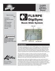
REPLACEMENT JACKS (LEGS)Internal Spring External Spring <strong>Power</strong> Level JackMeasurements in inchesInternal Spring Jacks <strong>and</strong> Rebuild KitsLeveling jack # Rebuild kit # Dimensions500385 kit # 800137S A=22.25 B=3.625500070 kit # 800131S A=22.25 B=4.0500145 kit # 800131S A=22.25 B=4.0500386 kit # 800130S A=22.375 B=4.5500620 kit # 800130S A=22.375 B=4.5500620 has a mounting pad width of 7.25External Spring jacksJack # Spring # Rebuild kit # Dimensions500082 500094 kit # 800129S A=20.75 B=3.25500146 500094 kit # 800129S A=20.75 B=3.25500272 500094 kit # 800129S A=20.75 B=3.25500235 500252 kit # 800129S A=18.3 B=3.25500498 500252 kit # 800129S A=18 B=3.25500384 500590 kit # 800132S A=21.25 B=2.625 (800132 kits <strong>for</strong> 2001 <strong>and</strong> later only)500598 500590 kit # 800132S A=21.25 B=2.625 (800132 kits <strong>for</strong> 2001 <strong>and</strong> later only)500482 500591 kit # 800132S A=18 B=2.625 (800132 kits <strong>for</strong> 2001 <strong>and</strong> later only)500600 500591 kit # 800132S A=18 B=2.625 (800132 kits <strong>for</strong> 2001 <strong>and</strong> later only)<strong>Power</strong> Level JacksJack # Spring # Rebuild kit # Dimensions500730 500591 kit # 800133S A=19.15 B=2.25 C=16 D= 8.0500832 500591 kit # 800133S A=23.25 B=2.25 C=22.3 D= 8.0500842 500591 kit # 800133S A=20.4 B=2.25 C=19.5 D=14.3 E=2.5500876 500591 kit # 800133S A=18.94 B=2.25 C=17.0 D=12.3 E= .5500933 500591 kit # 800133S A=19.75 B=2.25 C=17.75 D=12.3 E=1.5500759 500094 kit # 800138S A=20.85 B=2.6 C=17.6 D= 8500833 500094 kit # 800138S A=23.15 B=2.6 C=22.2 D=14.3 E=3.0500843 500094 kit # 800138S A=21.15 B=2.6 C=20.2 D=14.3 E=1.0500932 500094 kit # 800138S A=25.3 B=2.6 C=24.4 D=14.3 E=5.0500800 500094 kit # 800199S A=19.2 B=3.25 C=16.75 D= 8.06
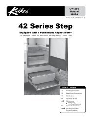
VERTICAL PUMP ASSEMBLIES2003 - PRESENT1102119864367ITEM PART # DESCRIPTION QTY APPLICATION500721 Complete power unit (1.5 gal. capacity)1 - 11500888 Complete power unit w/ <strong>manual</strong> override valves500893 Complete power unit1 2003 - present500911 Complete power unit500505 Valve manifold assembly (used w/ pump # 500893) 1 1999 - present8,9500641 Valve manifold assembly (used w/ pump # 500721)500595 Valve manifold assembly (used w/ pump # 500911)1 2003 - present500454 Valve manifold assembly w/ <strong>manual</strong> override valves (used w/ 50088)2 800302 Motor + Bearing14 800036S Tank replacement <strong>service</strong> kit (2.0 gal only)1999 - present07-1238 Fill plug6130-1214 Breather cap/dip stick (used with pump # 500911 only)130-1214 Push-in breather cap <strong>and</strong> dipstick1 1999 - present030-1040 Grommet, push-in breather cap5 07-1239 Drain plug 1 1999 - present7 500118 Fluid sensor assembly 1 1999 - present11500661 Pump harness 1500894 Pump harness w/ Packard connectors 12003 - present10500097 Dump valve assembly500440 Dump valve assembly w/ <strong>manual</strong> override1 1994 - present1 500310 Motor solenoid 1 1999 - present3 500685 Air breather 1 1999 - present13-1100 Pump/motor assy. (used with pump assembly # 500893) 1 1999 - present1,2,4,5,613-1138 Pump/motor assy. (used with pump assembly # 500721)130-1162 Pump/motor assy. (used with pump assembly # 500888)1 2003 - present130-1189 Pump/motor assy. (used with pump assembly # 500911)9500099 Leg valve assembly500439 Leg valve assembly w/ <strong>manual</strong> override3 1994 - present57
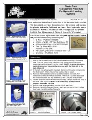
THE DIFFERENCE IS IN THE DETAILSP/N:SIZE:MISHAWAKA, INDIANAS/N:500812HORIZONTAL PUMP ASSEMBLIES62003 - PRESENT1342Weep HoleHYDRAULIC POWER UNITlevel5879ITEM PART # DESCRIPTION “A” QTY APPLICATIONComplete 3-valve pump assy500773 1.0 gal. capacity w/ <strong>manual</strong> override valves 11.0” 1 2003 - present1-8 500781 1.6 gal. capacity w/ <strong>manual</strong> override valves 9.0” 1 2003 - present500825 1.0 gal. capacity w/o <strong>manual</strong> override valves (obsolete) 11.0” 1 2002 - 2004Complete 4- valve pump assy500197 1.5 gal. capacity w/o <strong>manual</strong> override valves (obsolete) 1 1992-1995500910 1.0 gal. capacity w/o <strong>manual</strong> override valves (replaces pump # 500825) 9.8” 1 2003 - present1-9500920 1.4 gal. capacity w/o <strong>manual</strong> override valves 13.3” 1 2003 - present500925 1.4 gal capacity w/ <strong>manual</strong> override valves 13.3” 1 2003 - present501000 1.0 gal capacity w/ <strong>manual</strong> override valves 9.8” 1 2004 - present501013 1.4 gal capacity w/ <strong>manual</strong> override valves 13.3” 1 2004 - presentManifold assembly w/ <strong>manual</strong> override valves500772 Manifold assy. pump #’s 500773 & 500781 1 2003 - present1-2 500960 Manifold assy. pump #’s 500925 & 501000 1 2003 - present500641 Manifold assy. pump # 501013 1 2004 - presentManifold assembly w/o <strong>manual</strong> override valves1-2 500959 Manifold assy. pump #’s 500910 <strong>and</strong> 500920 1 2003 - present1500099 Leg valve assembly 3 1994 - present500439 Leg valve assembly w/ <strong>manual</strong> override 3 1994 - present3 140-1146 Fluid sensor 1 2002 - present130-1213 Breather cap <strong>and</strong> dipstick 1 2002 - present4 130-1214 Push-in breather cap <strong>and</strong> dipstick (pump assy. 500781) 1 2003 - present030-1040 Grommet, push-in breather cap 1 2003 - present5130-1194 1.0 gal. reservoir 1 2003 - present130-1196 1.4 gal. reservoir 1 2003 - present6 500661 Pump harness 1 2002 - present800302 Motor + Bearing only1 2002 - present130-1150 Pump/motor assy. <strong>for</strong> power unit assy’s 500773 <strong>and</strong> 5008257 130-1151 Pump/motor assy. <strong>for</strong> power unit assy 500781 1 2003 - present130-1193 Pump/motor assy. <strong>for</strong> power unit assy’s 500910 <strong>and</strong> 501000 1 2003 - present130-1195 Pump/motor assy. <strong>for</strong> power unit assy’s 500920 <strong>and</strong> 500925 1 2003 - present8 500310 Motor solenoid 1 1994 - present9500097 Dump valve assembly w/o <strong>manual</strong> override 1 1994 - present500440 Dump valve assembly w/ <strong>manual</strong> override 1 1994 - present8“A”
3 OR 4 JACK (LEG) VALVE ASSEMBLY1999 - PRESENTValve manifold assemblyITEM PART # DESCRIPTION QTY APPLICATION1,3,4 500636S Rear hose connector kit 1 1999- present1,3,6 500637* Front hose connector kit 1 1999- present5500099 Leg valve kit 11994- present500439 Leg valve kit w/ <strong>manual</strong> override 18 500523 O-ring kit 1 1999- present500505 Valve manifold assembly, pump # 500893 1 1999- present500641 Valve manifold assembly, pump # 5007211-7500454 Valve manifold assembly, pump # 500888500772 Valve manifold assembly, pump # 500773 & 500781500960 Valve manifold assembly, pump # 500925 & 501000500959 Valve manifold assembly, pump # 501013*”F” port has 2 springs1 2003- present9
FLUID SENSORS32ITEM PART # DESCRIPTION QTY APPLICATION1 500199 Fluid sensor 1 Jan. 1993-present2 500450 Fluid sensor w/ Packard connector 1 Nov. 1995-present3 140-1146 Horizontal pump assy. fluid sensor 1 Jun. 2002-present10
HOSES AND FITTINGSHose #080-XX XXX - IILeft hose fittingRight hose fittingLetterABCDEFGHose fitting at each endDefinition#4 37 deg female swivel end, 7/16-20 thread per S.A.E.J514/J.I.C#6 37 deg female swivel end, 9/16-18 thread per S.A.E.J514/J.I.C90 deg short bend tube, #4 37 deg female swivel 7/16-20thread per S.A.E. J514/J.I.C90 deg short bend tube, #6 37 deg female swivel 9/16-18thread per S.A.E. J514/J.I.C45 deg short bent tube, #4 37 deg female swivel 7/16-20thread per S.A.E. J514/J.I.C#4 37 deg male rigid end 7/16-20 thread per S.A.E.J514/J.I.C#6 37 deg male rigid end 9/16-18 thread per S.A.E.J514/J.I.CxExample: Hose assembly # 080-AA264-II is 264inches long, with #4 37 deg female swivel endfittings on both ends.xFittings:070-1261 070-1267 070-1268 070-1269070-1262Reducers:070-1258 070-126311
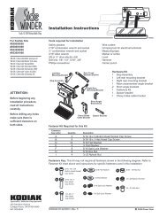
MANUAL TOUCH PAD CONTROL2004-present500731 touchpad (front view) 500731 touchpad (rear view)1423ITEM NOTE PART # DESCRIPTION QTY APPLICATION1 500731 Manual system touchpad 1 2004-present3 N5021-XXX Pump harness141-0005XXX Pump harness (with fuse)1 2004-present4 N5010-XXX5018-XXXSafety interconnect harness 1 2004-presentN=Part not shown“-XXX” = length of harness in inchesNote: See TIP Sheet # 204 <strong>for</strong> calibration instructions <strong>for</strong> this system. Calibration is required after installation.SEMI AUTO AND AUTO CONTROLSPLEASE SEE POWER GEAR TIP SHEET # 218 FOR INFORMATION REGARDINGUPDATING OF SEMI AUTO AND AUTOMATIC LEVELING TOUCH PADS ANDCONTROL BOXES12
SEMI-AUTOMATIC SEMI-AUTOMATIC TOUCH PAD CONTROL CONTROLS2002-2005500675 touchpad 500674 control box1 24563ITEM NOTE PART # DESCRIPTION QTY APPLICATION1 500675 Semi-auto touchpad Obsolete - use 500675S 1 2002-20052 N 500663 Auxiliary harness 1 2002-present3 N 5021-XXX Coach interconnect harness 1 2002-present4 N5020-XXX5018-XXXSafety interconnect harness 1 2002-present5 N 5019-XXX Touch pad harness Obsolete 1 2002-20056 500674 Control box Obsolete – use 500674S 1 2002-2005500673Semi-auto control kit (touchpad, control box,2002-presenttouchpad/control box harness)N=Part not shown“-XXX” = length of harness in inches2006-present140-1231 touchpad 140-1230 control box1 24563ITEM NOTE PART # DESCRIPTION QTY APPLICATION1 140-1231 Semi-auto touchpad 1 2006-present2 N 500663 Auxiliary harness 1 2002-present3 N 5021-XXX Coach interconnect harness 1 2002-present4 N5020-XXX5018-XXXSafety interconnect harness 1 2002-present5 N 141-0045XXX Touch pad harness 1 2005-present6 140-1230 Control box 1 2006-present1,5,6 500673Semi-auto control kit (touchpad, control box,2002-presenttouchpad/control box harness)N=Part not shown“-XXX” = length of harness in inchesNote: See TIP Sheet # 152 <strong>for</strong> calibration instructions <strong>for</strong> this system. Calibration is required after installation.13
AUTOMATIC TOUCH PAD CONTROL2002-20051 500629 touchpad 500630 touchpad24653ITEM NOTE PART # DESCRIPTION QTY APPLICATION1 500629 Auto touch pad Obsolete - use 500629S 1 2002-20052 N500771500787 Auxiliary harness 1 2002-present5013-XXX3 N 5021-XXX Coach interconnect harness 1 2002-present4 N 5020-XXX Safety interconnect harness 1 2002-present5 N 5019-XXX Touch pad harness Obsolete 1 2002-20056 500630 Control box Obsolete – use 500630S 1 2002-2005500643Automatic control kit (touchpad, control box, 1touchpad/control box harness)2002-presentN=Part not shown“-XXX” = length of harness in inches2006-present1 140-1226 touchpad 140-1227 control box42653ITEM NOTE PART # DESCRIPTION QTY APPLICATION1 140-1226 Auto touch pad 1 2006-present2 N500771500787 Auxiliary harness 1 2002-present5013-XXX3 N 5021-XXX Coach interconnect harness 1 2002-present4 N 5020-XXX Safety interconnect harness 1 2002-present5 N 141-0045XXX Touch pad harness 1 2006-present6 140-1227 Control box 1 2006-present1, 5, 6 500643Automatic control kit (touchpad, control box, 1touchpad/control box harness)2002-presentN=Part not shown“-XXX” = length of harness in inchesNote: See TIP Sheet # 153 <strong>for</strong> calibration instructions <strong>for</strong> this system. Calibration is required after installation.14
Wiring diagram <strong>for</strong> systems with control #’s 500731, 500675 & 140-1231, 500674 & 140-1230, 500629& 140-1226, 500630 & 140-1227Leveling Control BoxP/N’s:500630 & 140-1227500674 & 140-1230Manual Touch Pad P/N:500731** Horizontal pump assemblies 500773, 500781, <strong>and</strong> 500825do not use a dump valve assembly.15 1
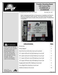
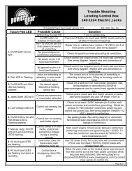
TROUBLESHOOTINGSYSTEM WILL NOT TURN ON, INDICATOR LIGHT DOES NOT LIGHTPROBABLE CAUSECORRECTIVE ACTIONCoach ignition not in run position Turn ignition to run positionTransmission not in park or neutral Place transmission in park or neutralParking brake not setSet brakeControl has been left on <strong>for</strong> more Push on/off button twicethan four minutes, auto shut off hasoccurredPin #5 of the 6 pin connector on the control must have +12 VDC with ignition in run position,No power to controlcheck coach fuse or breakerGround wire disconnected or shorted Pin #1 of the 8 pin connector is the main ground. Test <strong>for</strong> continuity with ground.Check <strong>for</strong> voltage at pin #6 at the 6 pin connector on the control. If it has 12v+ make sure pinNeutral safety switch wires shorted #2 also has 12v+. If it is ground, try grounding pin #2. If the control then operates, repair orreplace wires or neutral safety switchParking brake wire not grounded, or Check continuity between pin #1 of the 6 pin connector <strong>and</strong> ground. If there is no continuity,faulty parking brake switch the switch is bad, the parking brake is not set, or the wires to the switch are bad.Faulty controlIf all previous causes <strong>and</strong> actions do not apply replace controlJACKS WILL NOT EXTEND, PUMP IS NOT RUNNINGPROBABLE CAUSECORRECTIVE ACTIONMotor solenoid wire defectiveNo power from battery to pumpBad ground to pump motorMotor solenoid faultyPump motor faultyFaulty controlCheck <strong>for</strong> power at the blue solenoid signal wire while front or rear button is pushed (pin #3 ofthe 8 pin connector). If no power, check wires, <strong>and</strong> control..Check <strong>for</strong> +12 VDC at the large battery terminal of the solenoid, if no voltage recharge batteryor replace power cable.Add new ground cable from pump motor to chassis battery; check chassis ground connectionCheck <strong>for</strong> power at the blue solenoid signal wire while jacks down button is pushed. If nopower, check wires, <strong>and</strong> control. If power is present, connect +12 VDC to motor side terminalof solenoid; if motor runs, replace solenoidCheck <strong>for</strong> continuity between the motor <strong>and</strong> ground. Connect +12 VDC to motor sideterminal of solenoid; if motor does not run, replace pump motor (see TIP sheet 216 <strong>for</strong>details).If all previous causes <strong>and</strong> actions do not apply replace controlJACKS WILL NOT EXTEND, PUMP IS RUNNINGPROBABLE CAUSECORRECTIVE ACTIONFluid level low; pump cavitating Fill tank to proper level with automatic transmission fluid see tip sheet 140Check <strong>for</strong> ground at the black wire <strong>for</strong> each solenoid valve. If none, repair the wire.While pushing the button <strong>for</strong> "jacks down" check <strong>for</strong> 12 v + at the control wire <strong>for</strong> eachsolenoid valve, if none check <strong>for</strong> voltage at these wires where they exit the controller. IfPump harness faultyvoltage is present, repair the wires.If no voltage is present check the controller <strong>for</strong> trouble codes (see tip sheet 184). If notrouble codes check <strong>for</strong> proper signals on the 6 pin harness see "system will not turn on,indicator light does not light ". If proper signals are present, replace the controller.It is possible to use a leg valve to diagnose by swapping the dump valve <strong>and</strong> one leg valve. Ifthe system then builds pressure the dump valve is bad (the leg that now has the dump valveDump valve stuck open or faulty will malfunction). Replace dump valve <strong>and</strong> return leg valve to original position.NOTE- If there still is no pressure after swapping the valves, the pump may be faulty. SeeTIP sheet 215 <strong>for</strong> pump diagnostic details.See TIP sheet 215 <strong>for</strong> details. Remove tank <strong>and</strong> disassemble pump <strong>for</strong> visual inspection.Pump itself is damagedLeg solenoid wires damagedValve solenoids mis-wiredCheck <strong>for</strong> 12 V + at leg coil wires from control while pushing the button "front" or "rear" <strong>for</strong>that jacks valve. If no 12 V + signal, check <strong>for</strong> continuity on each wire between coil <strong>and</strong>controller. Good wire = bad control. Check <strong>for</strong> ground at the black wire <strong>for</strong> each solenoidvalve coil. Repair if necessaryCheck wiring diagrams161
ONLY FRONT JACKS WILL NOT EXTEND, PUMP IS RUNNINGPROBABLE CAUSECORRECTIVE ACTIONLeg solenoid wires damagedValve solenoid coil defectiveFront jack valve faultyCheck <strong>for</strong> 12 V + at leg coil wires from control while pushing the button "front" or "rear" <strong>for</strong>that jacks valve. If no 12 V + signal, check <strong>for</strong> continuity on each wire between coil <strong>and</strong>controller. Good wire = bad control. Check <strong>for</strong> ground at the black wire <strong>for</strong> each solenoidvalve coil. Repair if necessaryCheck coil <strong>for</strong> continuity, if none replace solenoid coilReplace cartridge valveANY ONE OF THE REAR JACKS WILL NOT EXTEND, PUMP IS RUNNINGPROBABLE CAUSECORRECTIVE ACTIONLeg solenoid wires damagedValve solenoid coil defectiveCartridge valve faultyCheck <strong>for</strong> 12 V + at leg coil wires from control while pushing the button "front" or "rear" <strong>for</strong>that jacks valve. If no 12 V + signal, check <strong>for</strong> continuity on each wire between coil <strong>and</strong>controller. Good wire = bad control. Check <strong>for</strong> ground at the black wire <strong>for</strong> each solenoidvalve coil. Repair if necessaryCheck coil <strong>for</strong> continuity, if none replace solenoid coilReplace cartridge valveALL JACKS WILL NOT RETRACT OR WILL NOT RETRACT FULLYPROBABLE CAUSECORRECTIVE ACTIONDump solenoid wires damagedCheck <strong>for</strong> 12 V + at leg coil wires from control while pushing the button "front" or "rear" <strong>for</strong>that jacks valve. If no 12 V + signal, check <strong>for</strong> continuity on each wire between coil <strong>and</strong>controller. Good wire = bad control. Check <strong>for</strong> ground at the black wire <strong>for</strong> each solenoidvalve coil. Repair if necessarySystem overfilled with fluid Drain fluid to recommended level-see tip 140System is operating as if the jacksare already retractedDump solenoid coil defectiveDump cartridge valve faultyCheck float switch operation. Check the float switch <strong>for</strong> proper orientation. Check the system<strong>for</strong> overfilling. Check <strong>for</strong> continuity on brown wire from float switch to control. Check <strong>for</strong>ground to float on black wire.Check coil <strong>for</strong> continuity, if none replace solenoidReplace valveANY ONE OR TWO JACKS WILL NOT RETRACT AT ALLPROBABLE CAUSECORRECTIVE ACTIONBroken jack spring (s) Replace jack spring see tip sheet 34Pin #5 of the 8 pin connector completes circuit <strong>for</strong> road side rear jackJack coil signal wire faultyPin #6 of the 8 pin connector completes circuit <strong>for</strong> curb side rear jackPin #7 of the 8 pin connector completes circuit <strong>for</strong> front jack (s)Check <strong>for</strong> continuity, if none replace wireJack coil ground wire faulty Check <strong>for</strong> ground at the coil terminal black wire repair if necessaryJack solenoid valve coil faulty Check coil <strong>for</strong> continuity, if none replace solenoidJack rod guide is rusted or dirtyClean chrome rod, grease rod guide if equipped with grease fittings. Otherwise lubricate withsilicone fluid. It may be necessary to reseal jack or replace.Jack valve faultyReplace cartridge valveShunt valve cloggedRemove hose fitting on manifold <strong>for</strong> that jack, to gain access to valve. Clean valve passageswith solvent <strong>and</strong> compressed air.Hose damagedReplace kinked, or damaged hose (damage may not be visible externally)PROBABLE CAUSEShunt valve cloggedShunt valve spring damagedHose damagedJack rod guide is rusted or dirtyInternal failure within jackANY JACK RETRACTS VERY SLOWLYCORRECTIVE ACTIONRemove hose fitting on manifold <strong>for</strong> that jack, to gain access to valve. Clean valve passageswith solvent <strong>and</strong> compressed air.Replace springReplace kinked, or damaged hose (damage may not be visible externally)Clean chrome rod, grease rod guide if equipped with grease fittings. Otherwise lubricate withsilicone fluid. It may be necessary to reseal jack or replace.Rebuild / replace components or jack as necessary.17 2
ANY JACK RETRACTS WITH NO POWER, WITH POSSIBLE POPPING SOUNDPROBABLE CAUSECORRECTIVE ACTIONCheck <strong>for</strong> coils in hose. Remove the coil if present then extend all jacks to full extension, thenAir in systemretract fully, repeat 4 cycles waiting a few minutes between cycles, check fluid level inbetween cyclesContaminated fluid Replace fluid, see page a3, tip sheet 140 <strong>and</strong> 141.Leg solenoid valves stuck open Remove solenoid valve, clean or replaceDump solenoid valve contaminated Remove solenoid valve, clean or replaceDump solenoid valve stuck open Replace solenoid valveAll solenoid valves stuck open Replace all valvesExtend jack legs, clean rod, lubricate with light weight grease if equipped with grease fittingsJack legs create popping soundor lubricate with silicone sprayDue to changes in temperature, exp<strong>and</strong>ing <strong>and</strong> contracting of fluid will magnify the problem ofpopping jacks, to help minimize this replace fluid with Mercon V fluidPANEL JACKS DOWN LIGHT WILL NOT GO ON WITH JACKS EXTENDEDPROBABLE CAUSECORRECTIVE ACTIONHarness wire faultyFluid sensor mis-adjustedFluid sensor faultyOpen on the brown wireDefective light on touch padCheck <strong>for</strong> ground at fluid sensor wires. Brown wire to control should read ground when jacksare down. Other wire should read ground at all times.See tip sheet 30, 54 or 81 <strong>for</strong> fluid sensor orientationCheck fluid sensor <strong>for</strong> continuity* with jacks extended, if no continuity, replace sensor *continuity: pre 2001 models, resistance should be near zero. For 2001 <strong>and</strong> newer units,resistance should be near 1 KWCheck <strong>for</strong> continuity between brown wire at float sensor <strong>and</strong> brown wire at control. If nonereplace wire.Apply +12 VDC at brown wire to 8 pin harness with key on. If no light. Replace touch pad,control, or both.PANEL JACKS DOWN LIGHT WILL NOT GO OFF WITH JACKS RETRACTEDPROBABLE CAUSECORRECTIVE ACTIONLow fluid level Fill tank with automatic transmission fluid see tip sheet 140Fluid sensor misadjustedSee tip sheet 30, 54 or 81 <strong>for</strong> fluid sensor orientationCheck fluid sensor <strong>for</strong> continuity* with jacks extended, if no continuity, replace sensor * : preFluid sensor faulty2001 models, resistance should be near zero. For 2001 <strong>and</strong> newer units, resistance shouldbe near 1 KWControl faultyIf all other probable causes have been checked, replace control <strong>and</strong> touch pad.JACKS DOWN LIGHT AND ALARM WILL GO ON WHILE DRIVING, JACKS RETRACTEDPROBABLE CAUSECORRECTIVE ACTIONLow fluid level Fill tank with automatic transmission fluid see tip sheet 140Fluid sensor misadjustedSee tip sheet 30, 54 or 81 <strong>for</strong> fluid sensor orientationCheck fluid sensor <strong>for</strong> continuity* with jacks extended, if no continuity*, replace sensor: preFloat sensor faulty2001 models, resistance should be near zero. For 2001 <strong>and</strong> newer units, resistance shouldbe near 1 KWShort in harnessCheck float switch wires <strong>for</strong> open circuit.SYSTEM LEVELS OK BUT RETRACTS WHEN KEY IS TURNED OFFPROBABLE CAUSECORRECTIVE ACTIONImproper wiring to 6 pin harness. See tip sheets 195, 196, 197, 199, 200, 204, 205SYSTEM JUMPS DOWN SLIGHTLY AS KEY IS SHUT OFFPROBABLE CAUSECORRECTIVE ACTIONImproper wiring to 6 pin harness.See tip sheets 195, 196, 197, 199, 200, 204, 205LEVELING SYSTEM DUMPS WHEN KEY IS PUT INTO ACC POSITIONPROBABLE CAUSECORRECTIVE ACTIONImproper wiring to 6 pin harness See tip sheets 195, 196, 197, 199, 200, 204, 20518 3
SYSTEM WILL NOT AUTO RETRACT WHEN THE CHASSIS IS PUT INTO DRIVEPROBABLE CAUSECORRECTIVE ACTIONImproper wiring to 6 pin harness. See tip sheets 195, 196, 197, 199, 200, 204, 205Check <strong>for</strong> voltage at pin #6 at the 6 pin connector on the control. If it has 12v+ make sure pinNeutral safety switch wires shorted #2 also has 12v+. If it is ground, try grounding pin #2. If the control then operates, repair orreplace wires or neutral safety switchSYSTEM DOES NOT GO TO CORRECT LEVEL POSITIONPROBABLE CAUSECORRECTIVE ACTIONControl / level needs to beSee tip sheet 147, 152, or 153,recalibratedFaulty controlIf previous causes <strong>and</strong> actions do not apply replace controlControl box is not mounted in proper Arrow on control box must point <strong>for</strong>ward. Mounting flange <strong>for</strong> control box must be on top,orientationwith wire harnesses coming out the bottom.TOUCH PAD LIGHTS ARE FLASHINGCORRECTIVE ACTIONPROBABLE CAUSEJacks are still down partially Press retract all jacks button to allow jacks to fully retractPossible trouble code being See tip sheet 184 <strong>for</strong> trouble codes <strong>and</strong> correctionsdisplayedFluid low, see tip sheet 140Coach is in emergency retract mode Sensor in pump tank is misadjusted see tip sheets 30, 54,81SYSTEM TURNS ON BUT TURNS OFF AS SOON AS A BUTTON IS PUSHEDPROBABLE CAUSECORRECTIVE ACTIONLow system voltageVoltage must remain above 10 volts while in operation-check battery condition <strong>and</strong>connections.194
POWER GEARLIMITED WARRANTY<strong>Power</strong> <strong>Gear</strong> warrants to the original retail purchaser that the product will be free from defects in material <strong>and</strong>workmanship <strong>for</strong> a period of (2) years following the retail sales date. <strong>Power</strong> <strong>Gear</strong> will, at its option, repair or replace anypart covered by this limited warranty which, following examination by <strong>Power</strong> <strong>Gear</strong> or its authorized distributors or dealers,is found to be defective under normal use <strong>and</strong> <strong>service</strong>. No claims under this warranty will be valid unless <strong>Power</strong> <strong>Gear</strong> orits authorized distributor or dealer is notified in writing of such claim prior to the expiration of the warranty period.Warranty is transferable pending documentation of original sale date of product.THIS WARRANTY SHALL NOT APPLY TO:• Failure due to normal wear <strong>and</strong> tear, accident, misuse, abuse, or negligence.• Products which are modified or altered in a manner not authorized by <strong>Power</strong> <strong>Gear</strong> in writing.• Failure due to misapplication of product.• Telephone or other communication expenses.• Living or travel expenses.• Overtime labor.• Failures created by improper installation of the product’s slideout system or slideout room to include final adjustmentsmade at the plant <strong>for</strong> proper room extension/retraction; sealing interface between slideout rooms <strong>and</strong> side walls;synchronization of inner rails; or improper wiring or ground problems.• Failures created by improper installation of <strong>leveling</strong> systems, including final adjustments made at the plant, or low fluidlevel, wiring or ground problems.• Replacement of normal maintenance items.There is no other express warranty other than the <strong>for</strong>egoing warranty. THERE ARE NO IMPLIED WARRANTIES OFMERCHANTABILITY OR FITNESS FOR A PARTICULAR PURPOSE. IN NO EVENT SHALL POWER GEAR BE LIABLEFOR ANY INCIDENTAL OR CONSEQUENTIAL DAMAGES. This warranty gives you specific legal rights, <strong>and</strong> you mayalso have other rights, which vary from state to state. Some states do not allow the limitations of implied warranties, orthe exclusion of incidental or consequential damages, so the above limitations <strong>and</strong> exclusions may not apply to you.For <strong>service</strong> contact your nearest <strong>Power</strong> <strong>Gear</strong> authorized warranty <strong>service</strong> facility or call 1-800-334-4712. Warranty <strong>service</strong>can be per<strong>for</strong>med only by a <strong>Power</strong> <strong>Gear</strong> authorized <strong>service</strong> facility. This warranty will not apply to <strong>service</strong> at any otherfacility. At the time of requesting warranty <strong>service</strong>, evidence of original purchase date must be presented.<strong>Power</strong> <strong>Gear</strong>1217 E. 7 th StreetMishawaka, IN 46544800/334-4712www.powergearus.com205