
You also want an ePaper? Increase the reach of your titles
YUMPU automatically turns print PDFs into web optimized ePapers that Google loves.
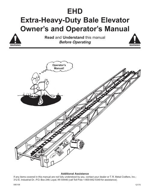
WARNING<strong>EHD</strong>Extra-Heavy-Duty Bale ElevatorOwner’s and Operator’s <strong>Manual</strong>Read and Understand this manualBefore OperatingWARNINGOperator’s<strong>Manual</strong>!Additional AssistanceIf any items covered in this manual are not fully understood by you, contact your dealer or T. R. Metal Crafters, Inc.;312 E. Industrial Dr.; P.O. Box 248; Loyal, WI 54446 (call Toll Free 1-800-842-5349 for assistance).08010812170
General Safety StatementIt is your responsibility as an owner, operator or supervisor to know what specific requirements, precautions and workhazards exist and to make these known to all other personnel working with the equipment or in the area, so that they toomay take any necessary safety precautions that may be required. Failure to read this Owner's and Operator's <strong>Manual</strong> andits safety instructions is a misuse of the equipment.Operator's<strong>Manual</strong>!The Operator's <strong>Manual</strong>Anyone who will operate or work around anelevator or transport shall first read theOwner's and Operator's <strong>Manual</strong>!WARNINGComplete sign-off sheet in "Operator Qualifications"section of this <strong>Manual</strong> to documenttraining.Safety Alert SymbolThis Safety Symbol means:Attention!Become Alert!Your Safety Is Involved!The Safety Alert Symbol identifies important safety messages on machines, safetydecals, in manuals, or elsewhere. When you see this symbol, be alert to the possibilityof personal injury or death. Follow the instructions in the safety message.This symbol will be used with one of three signal words:the degree of hazard.CAUTION WARNING DANGERto indicateCAUTIONWARNINGDANGER— Hazards or unsafe practices which COULD result in minor personal injury or product or propertydamage.— Hazards or unsafe practices which COULD result in severe personal injury or death.— Immediate hazards which WILL result in severe personal injury or death.Why is Safety important to You?• Accidents Disable and Kill3 Big Reasons: • Accidents Cost• Accidents Can Be Avoided11160412170
1ForewordThis <strong>Manual</strong> is intended to point out some of the basic situationswhich may be encountered during the normal operation andservice of your machine and to suggest possible ways ofdealing with these conditions.Additional precautions may be necessary, depending onconditions at the worksite or in the service area. Themanufacturer has no direct control over machine application,operation, inspection, lubrication, or maintenance. Therefore,it is your responsibility to use good safety practices in theseareas.Other information which may affect the safe operation of yourmachine may be contained on safety decals, or in insurancerequirements; employer’s safety programs; safety codes; andlocal, state/provincial, and federal laws, rules, and regulations.If you require information not covered in this manual, contactT. R. Metal Crafters, Inc.; 312 E. Industrial Drive; P.O. Box248; Loyal, WI 54446 (call Toll Free 1-800-842-5349).Because our engineers are constantly improving products, T. R. Metal Crafters, Inc. reserves the right to change design and/or specificationswithout notice. The information on this document does not constitute a warranty by T. R. Metal Crafters, Inc.111604 12170
2Table of ContentsGeneral Safety Statement .............................. Inside Front CoverForeword ................................................................................... 1Decal Location........................................................................... 3Operator Qualifications and Sign Off Sheet .............................. 4Operating InstructionsMaximum Angle of Elevation for Various Bale Lengths ..... 5Machine Inspection ...................................................... 6,7Winch Operating Instructions.......................................... 8Movement and Placement ....................................... 9 - 11Electric Motor Drive ...................................................... 12Safety Lockouts and Horsepower Requirements ......... 13Work Area Diagram ............................................... 14 - 15Elevator Operation ........................................................ 16Bale Kick-off Operation and Assembly .................. 18 - 19Elevator Shutdown ....................................................... 20Optional Accessories............................................................... 21Trouble Shooting .............................................................. 22 - 28Service and Maintenance ........................................................ 29Operating Heights and General Dimensions ..................... 30, 31Layout Guide ..................................................................... 32, 33Assembly Instructions ...................................................... 34 - 44Serial No. and Model No. Plate Location Guide ................. InsertWarranty ......................................................... Inside Back Cover11160412170
The Decals Shown On This Page Must BeDisplayed As Shown BelowFREE REPLACEMENTS ARE AVAILABLE UPON REQUEST3Contact T. R. Metal Crafters, Inc.; 312 E. Industrial Drive; P.O. Box 248; Loyal, WI 54446(Call Toll Free 1-800-842-5349)• Safety decals must be replaced if they are destroyed, missing, painted over, or can no longer be read.• New equipment components installed during repair shall be equipped with the same safety decals that were affixed tothe original components.• Keep decals wiped clean at all times.4654WILLWILL48refer to Parts List11160412170
4Operator Qualifications and Sign Off SheetOperation of this machine shall be limited to competent and experienced persons. In addition, anyone whowill operate or work around this machine must use good common sense. In order to be qualified, he mustalso know and meet all other requirements, such as:1. Some regulations specify that no one under the age of 18 may operatepower machinery. This includes this machine. It is your responsibility toknow what these regulations are in your own area or situation.2. Current OSHA regulations state in part: “At the time of initial assignmentand at least annually thereafter, the employer shall instruct every employeein safe operation and servicing of all equipment with which theemployee is, or will be involved” (per Federal Occupational Safety andHealth Standards for Agriculture Subpart D, Section 1928.57 (a) (6))3. Complete sign off sheet below to document training.4. A person who has not read and understood all operating and safetyinstructions, is not qualified to operate this machine.5. It is the responsibility of the owner, qualified operator/s or supervisor/s tosee that no unqualified persons are allowed to operate this machine andthat unqualified persons (especially children) stay out of the work area.CAUTIONAs a requirement of OSHA, it is necessary for the employer to train the employee in the safe operation and servicing of thismachine at the time of initial assignment and at least annually thereafter. Use this sign off sheet to document training.Date Employer Signature Employee Signature11160412170
Maximum Angle of Elevationfor Various Bale Lengths5BaleLengthMaximumElevation Angle20" 30º24" 35º30" 40º36" 45ºGot a Question?If any items covered in this manual are not fully understood by you, contactyour dealer or T. R. Metal Crafters, Inc.; 312 E. Industrial Dr.; P.O. Box 248;Loyal, WI 54446 (call Toll Free 1-800-842-5349 for assistance).01010812170
6Machine InspectionInspect machine after delivery, upon completion of assemblyand before each use. Machine inspection is mandatory.Replace ThisSafety Decal!All GuardsCheck that all guards are in place, secured, and functional. Forinformation about guards, their location and free replacements, seepage 44 of this manual.Check all safety decals and replace any thatare worn, missing, or illegible. For informationabout safety decals, their location, and freereplacements, see page 3 or this manual.DischargeEndSafety CableWARNINGDo not mount a longer or shorterlength elevator than recommendedbelow on transport. Failure to heedcould result in personal injury or death.Model HST-10T Fits only T. R. Metal Crafter’s elevatorsModel HST-20T Fits only T. R. Metal Crafter’s elevatorsModel HST-40T Fits only T. R. Metal Crafter’s elevatorsHECStandardElevator Length<strong>EHD</strong>Extra-Heavy-DutyElevator Length20' - 32' 24' - 30'36' 36' - 48'N/A 54' - 60'Make sure the safety cable is installed onto transport at the correct location. Refer to Transport <strong>Manual</strong> for instructions.The safety cable prevents transport from being lowered to an unsafe working position. Failure to install safety cable mayresult in personal injury or death. Note: Elevator weight should never rest on transport safety cable during normal operation.If safety cable is lost or missing, contact T. R. Metal Crafters, Inc. for free replacement.07010812170
Machine Inspection7Winch and CableWARNING1. Are all fasteners tight?DANGERCheck winch and cable for condition, security, and operation. Thereshould be at least 3-complete wraps of cable around winch drumin full down position. The cable anchor on the winch drum mustbe tight.2. Are all belts and chains properly adjusted?(See Service and Maintenance Section of thismanual).3. Check all lubrication points. (See Service andMaintenance Section of this manual).Cable ClampsThimbleRight Way: for maximum rope strengthDead Endof CableU SectionWrong Way: clips staggered111604DANGERWrong Way: clips reversedThe correct way to attach cable clamps is shown at the top; the “U”section is in contact with the rope’s dead end and is clear of the thimble.12170
8Winch Operating InstructionsDANGERRead Carefully: Instructions for Safer Operation of your WinchThis winch is of general purpose design. The load rating is based on an intermittent duty cycle.High forces may be created by use of winch, creating potential safety hazards. DANGER Donot allow anyone who is not familiar with these operating instructions to operate the winch.DANGER This winch is not designed to be a human hoistand should never be operated when there are personspositioned on or under the load being moved. The winch isdesigned for raising the elevator weight only! Do not liftother items with the elevator.1. The winch must be securely bolted down to its mountingplate. The cable must be securely fastened to the transportand to the winch drum.2. Never fully extend the cable. Always keep at least three(3) complete turns of cable around the drum. Otherwisecable can pull loose from the drum.3. Always be sure the cable is pulling straight off the winch -not at an angle. This will prevent the cable from rubbingagainst the sides of the drum and becoming damaged.4. Never stand along side the winch cable or guide the cablewith your hands. Always inspect the cable and cableclamps for damage before each use. Replace the cable ifit is frayed or kinked. If the cable breaks, it can act like awhip and inflict serious injury to anyone in the path of thecable.5. Never permit anyone to stand on or under the elevatorwhen it is being raised, lowered or pulled. DANGERThis machine is not grounded. Keep at least 10 feet awayfrom overhead electrical wires and obstructions.Electrocution can occur without direct contact.6. Elevator should be in the down position or secured tobuilding when unattended as unauthorized persons mayattempt to operate the winch, thereby creating an unsafecondition.7. Never lower transport to straight-out position — transportlegs may bend due to increased stress.8. Always keep the winch lubricated per instructions.Remember, worn-out parts cause unsafe conditions.This winch is equipped with a brake that isactuated by turning the handle. The brake isdesigned to hold the load whenever the handleis released.1. Never operate winch with wet or oily hands andalways use a firm grip on the handle.2. To raise the elevator, turn the handle clockwiseand listen for the “loud clicking sound” of theratchet. If the clicking sound stops, keep a firmgrip on the handle and return the elevator tothe down position by turning the handlecounterclockwise. Repair the winch.3. To lower the elevator, turn the handlecounterclockwise (no clicking sound)–theratchet pawls should be fully engaged into theratchet gear teeth. To stop while lowering theload, turn the handle clockwise until you heartwo clicks (about 6 inch movement of thehandle). Note: If your hand slips off of the handlewhile turning it counterclockwise, the brake willprevent the handle from spinning backwards.DANGER The brake is not fully lockeduntil the handle Is turned clockwise farenough to hear two clicks.4. To pull the cable off the winch without a load,you must pull on the cable and turn the handlecounterclockwise at the same time. The Load-Lok brake is always actuated so the winch cannot freewheel.5. Always inspect the brake disc for wear prior toeach use. If less than 1/16" thick, cracked orbroken, it should be replaced.WARNING The brake disc will get hotwhen lowering the load. If brake is smoking orsqueals, stop lowering and let the brake coolfor 15 minutes. Do not touch brake.11160412170
Movement and Placement9RightWrongLocking Hitch Pin20 mphMaximumLockingHitch PinWARNING1. Elevator must be empty and in down position (with light tension on safety cable), beforemoving.2. Use a locking hitch pin.3. Transports are designed only for towing at tractor speeds up to 20 mph between sunrise andsunset. Check and comply with all state and local regulations governing marking, lighting,towing and maximum width.RightWrongUtility Lines10 Feet AwayLowerElevatorKEEPAWAYNORIDERSDANGER1. This machine is not insulated. When moving, upper end can contact electric utility lines andoverhead obstructions.2. Lower elevator well below level of power lines before moving.1116043. Keep at least 10 feet away from overhead electrical wires and devices. Electrocution canoccur without direct contact.12170
10Movement and PlacementSlow and EasyNo RidersWARNING1. Do not allow anyone to ride on or stand below elevator and/or transport at any time.2. Care should be exercised when traveling on rough and uneven terrain to avoid upsetting.3. Leave elevator in recommended down position until final positioning requires raising it.Electrical WiresEveryone ClearDANGER1. Never move the elevator manually. Use a vehicle. When releasing from or attaching to the vehicle,test the hitch end for downward weight. Lift it slowly and keep the hitch end no higher thanthe tractor tow bar. Be sure elevator is empty before lifting or moving.2. During placement, make sure entire area above elevator and in line of travel is clear of obstructionsand electrical wires. Failure to stay clear of electrical wires will result in electrocution.1116043. Move elevator slowly into working position with towing vehicle, not by hand. Make certain everyoneis clear of the work area. 12170
Movement and Placement11MinimumDistanceLevelWARNINGLevel Area !Vehicle Attached !12170Keep distance between elevator and barn to a minimum when positioning a raised elevator. Theelevator must be on a level surface, attached to a vehicle, and the wheels must be free to movewhen raising or lowering.1. Once in place, the elevator should be anchored at the hitchend and/or supported at the discharge end. The wheelson the elevator should be chocked on both sides.DANGER2. Do not attempt to increase elevator height by positioningwheels on lumber, blocks, or by other means. Failure toheed may result in personal injury or death.Anchor111604Wheel Chocks(on both sides of both wheels)
12Electric Motor DriveDANGER1. Electric motors and controls shall be installed by a certified electrician and must meet thestandards set by the National Electrical Code and all local and state codes.2. A magnetic starter should be used to protect your motor.WARNING3. Electric motor must be totally enclosed, fan cooled and have a manual reset overload protector.Use a motor that is rated between 1725 to 1800 RPM.4. Be sure that the wiring to the electric motor is large enough and the power source is theright voltage and frequency for the motor used. Make certain that all electrical assembliesare grounded and located in a weatherproof dry location.WARNING5. Do not operate equipment without all shielding in place.6. Keep electric motors and motor fans clean of hay and dust. This will allow motor to coolproperly.DANGER7. Be certain to keep all wiring and controls out of reach of livestock and children.8. Check and determine that the belts are in line.9. Make certain that the belts are snugged up but not overtightened. Overtightened belts willcause pulley and bearing failure. If belt tension is correct, belt can be depressed about 1/2"to 3/4" at midpoint between pulleys. Replace pulleys when pulley grooves are worn enoughto cause belt slippage.WARNING10. You must disconnect and lockout power source before resetting your motor (see lockout/tagout rules on following page).11. Reset and motor starting controls must be located so that the operator has full view of theentire operation.12. Use a 2.8" O.D. Type A, cast iron motor pulley (not included).13. Make certain that the motor horsepower is adequate and is properly matched to the motorpulley.WARNING14. Do not use an electric motor of lower horsepower than specified in our “Horsepower RequirementsGuide”. Failure to heed these instructions can result in personal injury or death!11160412170
New Lockout/Tagout Rule Becomes Effective13Main Power Disconnect SwitchWARNINGNew Occupational Safety and Health Administration (OSHA)regulations on locking out or tagging out equipment prior tomaintenance became effective October 31, 1989. The new rulerequires that any equipment subject to restarting be locked out— when possible — prior to servicing. When lockout is notpossible, equipment must be tagged.Previous lockout/tagout regulations allowed a choice betweenlocking and tagging. But the new rule permits sole use of warningtags only if the employer can prove that equipment cannot belocked out or that tagging is adequate protection.Employers are also required to thoroughly document exactly howworkers are to turn off equipment, disconnect it, and verify that ithas been de-energized. Workers, including contractors, must benotified of the lockout/tagout procedures.Lockout: A main power disconnect switchcapable of being locked only in the OFFposition shall be provided. This shall be lockedwhenever work is being done on theequipment.Safety Lockouts IllustratedHorsepower RequirementsBales should be “pulled toward” electric-motor drive end. However,if elevator is mounted on a transport, drive end must remain onground and “push bales”.Safety Lockouts In Use OnSwitch BoxesHorizontal ConveyorIncline Elevator1/2 HP 16' – 28' 1/2 HP 16' – 24'3/4 HP 30' – 44' 3/4 HP 28' – 40'1 HP 48' – 60' 1 HP 42' – 44'1-1/2 HP 64' – 90' 1-1/2 HP 48' – 60'2 HP 96' – 120'Use 2.8" O.D. Type A motor pulley on horizontal conveyor and incline elevator.Use a motor that is rated between 1725 to 1800 RPM.NOTE: The above chart is only a guide –– the size, shape and weight of your bales;angle of elevator; and desired speed may affect your installation. Remember, balesare more effectively pulled than pushed. Less horsepower is required when pulled!Attaches to main power disconnect switch.Equipment cannot be started until all workmenhave removed their personal padlocks.11160412170
14Work Area Diagram – Unloading Baled HayWARNING1. The work area shown below should be marked offwith barriers.2. It shall be the duty of the operator to see that childrenand/or other persons stay out of the work area!Trespass into the work area by anyone not involvedin the actual operation, or trespass into a hazard areaby anyone, shall result in an immediate shut downby the operator.3. Prior to start up and during operation, it shall be theresponsibility of the operator to see that the workarea has secure footing, is clean and free of all debrisand tools which might cause accidental tripping and/or falling.DANGERFallingHayBalesDANGERUnder elevator andunder transport areaKeep Out!WARNINGKEEP OUT OF SHADEDHAZARD AREAWheel ChocksWheel ChocksWARNINGWork AreaAuthorized Personnel OnlyWARNINGElevator Motor Drive AreaHazard — Keep Out!Chock All Wheels11160412170
15Work Area Diagram – Movement and PlacementDANGERDANGEROVERHEAD WIRESKEEP AWAY!Under elevator andunder transport areaKEEP OUT!WARNINGHAZARD AREAKEEP OUT!WARNINGKEEP OUT OF SHADEDHAZARD AREA11160412170
16Elevator OperationDANGERDo not allow persons to stand below or ride bales up elevator at any time.WARNING1. Observe work area restrictions.2. Keep all safety shields and devices in place.3. Make certain everyone is clear before operating or moving the machine.4. Keep hands, feet, hair, and clothing away from moving parts.5. Shut OFF power and lock out to adjust, service, or clean.Important Break-in InstructionsCheck and make sure that bearings on drive unit and tightener end contain grease. Pour a light stream of heavy oil ontoelevator chain before running elevator. Oil will reduce friction, quiet elevator and greatly extend chain life. Run emptyelevator for thirty minutes after final assembly. Because bolts do have a tendency to loosen and chains tend to flex afterinitial use, this will give you time to make the break-in adjustments and check that elevator functions properly before youstart making hay. Check and tighten any loose bolts. Elevator chain will loosen after use and should be readjusted in thefollowing order:1. Loosen chain tightener and remove extra links from conveyor chain.2. Connect and retighten conveyor chain until snug.Important — first remove extra chain links before using chain tightener. Failure to remove extra chain links willresult in chain tightener not being able to take up all of the slack chain.11160412170
17THIS PAGE LEFTINTENTIONALLYBLANK11160412170
18Bale Kick-off Operation and AssemblyWrongRightDANGERDANGERDo not knock bales off conveyor by hand. Use an Automatic Bale Kick-off available fromthe factory. Failure to heed these instructions will result in personal injury or death!111604Tapered design provides for unloading to either right or left along conveyor. Kick-off may be removed fromor installed onto conveyor without breaking the conveyor chain. Remove cotter pin #1 and pull out kick-offaxle #3 and spacer #2. Lift conveyor chain up from conveyor chain track. Conveyor chain should ride overgreen plastic wear strip and under kick-off axle. Reassemble kick-off axle, spacer and cotter pin.12170
Bale Kick-off Operation and Assembly19ArmGreen Plastic Wear StripFinForwardBackwardFinArmEach kick-off requires 3 control ropes. Use a 1/4" low-stretch grade, nylon rope. The length of each control rope is equalto the conveyor length plus distance of conveyor to barn floor. Install control ropes as shown in the following illustrations.Pull control rope #4 or #5 to change direction of unloading (right or left side of conveyor), or to slide kick-off backwardalong conveyor. Pull control rope #6 to slide kick-off forward along conveyor. Pulling one arm backward and raising thefin above it will automatically push the opposite arm forward, lowering the fin above it.To secure the kick-off during operation, tie the end of the control rope #4 or #5 to a sturdy anchor point. Use thecontrol rope #4 or #5 that is connected to the kick-off arm in the backward position. The side of the kick-off with thearm in the backward position is also the side of the kick-off with the fin in the up position. Securing the backward arm holdsthe fin in the up position and prevents a hay bale from pushing the kick-off along toward the end of the conveyor.Bales should not be run over the top of the kick-off and back down into the conveyor. The kick-off lifts the conveyor chainout of the conveyor chain track. When the bale travels over the top of the kick-off and back down into the conveyor, it maypush the chain off to the side of the conveyor chain track. The weight of the bale will hold the chain to the side of theconveyor chain track, and as it reaches the end of they conveyor, it may be derailed from the drive sprocket.11160412170
20Elevator ShutdownWARNING1. Empty Elevator2. Stop Unit3. Lockout PowerA. Normal Shutdown:1. Empty elevator before stopping unit.2. Lockout power source before operator leaves work area.B. Emergency Shutdown:WARNING1. Disconnect and lockout the power source if elevator shuts downunder load. Clear as much hay from elevator as you can. Neverattempt to restart when full.2. Starting the unit under load may result in damage to the elevator.Such damage is considered abuse of the equipment.Cleanup and StorageCAUTIONWhen the operation has been completed:1. Clean entire work area.2. Remove anchors, supports, and chocks.3. Move elevator slowly out of “working” position with towing vehicle -not by hand.4. If not in “transport” position, lower elevator to the “full down” positionimmediately upon clearance of any obstructions.5. Transport to the new work area or storage area. Observe previousmovement and placement instructions. Store elevator in the “fulldown” position with hitch end anchored.11160412170
Optional Accessories21Connector plates: Connects incline elevatorto horizontal mow conveyor. Prevents bales fromturning and tumbling out when transferring.Above drawing illustrates incline elevator assembledto horizontal conveyor, using Bale Guides (modelHST-7A), Connector Plates (model HST-17A or 18A)and Bale Arrangers (model HST-16A).Bale arrangers: Directs irregular shaped balesinto horizontal conveyor. Made of heavy galvanizedsteel.Bale chute(grate-type,6´ length)Hinges to elevator — tips back against wagon ortruck for easy unloading. Long-taper designautomatically lines up each bale to prevent themfrom tipping or turning while being conveyed upelevator. Grate-type construction permits loosematerial to fall through for smoother operation.Bale chute(pan-type; 4´ length)Hinges to elevator — rests onits own stand or tips back against wagon or truckfor easy unloading. Made of heavy, galvanizedsteel. Short-taper design automatically lines upeach bale to prevent them from tipping or turningwhile being conveyed up elevator.Bale guidesKeeps bale twine fromcatching and breaking when bales are dischargingfrom a steeply inclined elevator. Prevents balesfrom tipping and turning and then tumbling outwhen transferring from an inclined elevator to mowconveyor. Pair of sturdy steel tubes clamp ontosides of inclined elevator on top end.Bale railsRails increase height of elevator sides to preventirregular-shaped bales from tumbling out. Rigid12´ long steel rails clamp onto sides of inclinedelevator.(No. HST-40TTransport illustrated)Transports Engineered for better balance andgreater strength — now you can move yourelevator with ease to exactly where you want it.Rugged, oversize 2" x 3" x 1/8" steel tubingtransports are extra heavy for more strength.Wheels are set far apart for increased stability.Equipped with 15" four-bolt, ag-type wheel rims(less rubber tires) mounted on regreaseable,tapered roller bearings (max. speed – 20 mph).Transport can be quickly raised from towingposition up to 45º. Sturdy, easy-to-operate handwinch features double-disc, automatic brakesystem for positive load control. Winch is zincplated to resist rust.Bale kickoff Sturdy, tapered design providesfor fast, smooth, accurate unloading to eitherright or left from any point along conveyor. Pullcontrol rope (rope not included), from mow floorto change direction of unloading or to slidekickoff to any position along full length ofconveyor. Bales cannot be conveyed overkickoff and onward toward end of conveyor.Mow hangersMakes it simple and easy to installconveyor from hay track, rafters,or roof. Sturdy tubular steelhangers are extra wide toprevent bales from snagging.Recommended at ends andevery 12´ of conveyor lengthfor proper support.Transport hitchSpecially-designed, extra-long poleto prevent elevator from binding againsttractor or truck bumper during short turns —pole unpins for easy removal. Pin can be removedfrom rigid clevis to permit swiveling — preventstractor or truck hitch pin from binding when elevatoris raised.01010812170
22Symptom:Trouble Shooting GuideBales fall off elevator before reaching mow conveyor.Problem:Bales are not loaded onto elevator properly.Illustration AIllustration BWrongRight(End View)(End View)SOLUTION:Load bales as shown in Illustration A above or use a Bale Chute accessory (Model No. HST-5A orHST-12A), as shown below.Model No. HST-5ABale chute (grate-type, 6´ length): Hinges to elevator — tips backagainst wagon or truck for easy unloading. Long-taper designautomatically lines up each bale to prevent them from tipping or turningwhile being conveyed up elevator. Grate-type construction permitsloose material to fall through for smoother operation.Model No. HST-12ABale chute (pan-type; 4´ length): Hinges to elevator — rests on its ownstand or tips back against wagon or truck for easy unloading. Made ofheavy, galvanized steel. Short-taper design automatically lines up eachbale to prevent them from tipping or turning while being conveyed upelevator.SOLUTION:Use Bale Side Rail accessory (HST-6A)Bale rails: Rails increase height of elevator sides to prevent irregularshapedbales from tumbling out. Rigid 12´ long steel rails clamp onto sidesof inclined elevator.Problem:SOLUTION:Problem:SOLUTION:Problem:SOLUTION:Problem:SOLUTION:010108Hay possibly not being properly baled.Operate baler within speed range recommended by manufacturer to obtain properly baled hay.Bale string knots are breaking.Repair knot tieing mechanism in baler.Elevator positioned at too steep of an angle.Decrease elevator angle.Elevator speed is too fast.Use a 2.8" O.D. motor pulley.12170
Trouble Shooting Guide23Symptom:Problem:SOLUTION:Problem:SOLUTION:Conveyor chain breaks apart during operation.Loose conveyor chain catching on elevator.Tighten chain. Important — first remove extra chain links before using chain tightener. Failureto remove extra chain links will result in chain tightener not being able to take up all of the slackchain.Conveyor chain is worn out.Replace worn chain.Problem:SOLUTION:Chain return guides are worn out or defective.Replace chain return guides.Problem:SOLUTION:Elevator sprocket may have a bad tooth.Replace worn sprockets.Symptom:Problem:SOLUTION:Problem:SOLUTION:Problem:SOLUTION:Problem:SOLUTION:Conveyor chain become loose when conveyor is loaded, but snug when conveyor is empty.Elevator chain is not tightened properly.Tighten chain. Important — first remove extra chain links before using chain tightener. Failureto remove extra chain links will result in chain tightener not being able to take up all of the slackchain.Elevator too heavily loaded.Increase space between bales when loading elevator.Elevator positioned at steep angle.Decrease elevator angle.Bales are being “pushed away” rather than “pulled toward” electric motor drive end. This may result intop ”pushing” chain becoming slack and bottom “pulling” chain remaining snug.Reassemble elevator to pull bales toward electric motor drive end. Drive end must remain onground and push bales if elevator is mounted on a transport.11160412170
24Trouble Shooting GuideSymptom:Problem:SOLUTION:Elevator or conveyor tears hay loose from bottom side of bale.Elevator or conveyor tracks do not line up properly.Gently hammer tracks into alignment. Properly aligned tracks will not grab hay from bottom ofmoving bales.Tap corner down with hammerChainTravelTap corner down with hammerSymptom:Problem:SOLUTION:Bales travel over kick-off and down conveyor.Kick-off fin does not stay in up position.Secure kick-off with control rope (refer to illustration on page 18). When securing the kick-off, usethe control rope that is connected to the kick-off arm in the backward position. The side of thekick-off with the arm in the backward position is also the side of the kick-off with the fin in the upposition. Securing the backward arm holds the fin in the up position and prevents a hay bale frompushing the kick-off along toward the end of the conveyor.Bales should not be run over the top of the kick-off and back down into the conveyor. The kick-offlifts the conveyor chain out of the conveyor chain track. When the bale travels over the top of thekick-off and back down into the conveyor, it may push the chain off to the side of the conveyorchain track. The weight of the bale will hold the chain off to the side of the conveyor chain track,and as it reaches the end of the conveyor, it may be derailed from the drive sprocket.Symptom:Problem:SOLUTION:Symptom:Problem:SOLUTION:Bales are bunching up at the kick-off and not going over the side smoothly.Kick-off model does not match Conveyor model.Contact the factory for assistance in model identification.Bales travel up kick-off and wedge against the ceiling.Conveyor possibly hung too close toward ceiling.Lower the conveyor to increase ceiling clearance.11160412170
Trouble Shooting Guide25Symptom:Problem:Problem:Problem:Bales are bunching up at kick-off and not going over the side smoothly.Mow Conveyor is not setting level.Motor weight at drive end pulls one side of the conveyor down.Mow Hangers are not installed level.RightWrong(End View)(End View)SOLUTION:Clamp conveyor to a solid wood mow-hanger as shown below. Locate wood mow-hanger nearmotor drive end of conveyor, as weight imbalance (due to motor) is greatest at that point. Woodmow-hangers are not available from the factory.(End View)11160412170
26Trouble Shooting GuideSymptom:Symptom:Bales are bunching up at kick-off and not going over the side smoothly.Bales fall off conveyor before reaching the kick-off.Problem:Elevator is not loading bale onto conveyor properly.Illustration AIllustration BWrongRight(End View)(End View)SOLUTION:Use the accessories shown below.Connector plates: Connects incline elevatorto horizontal mow conveyor. Prevents bales fromturning and tumbling out when transferring.Above drawing illustrates incline elevator assembledto horizontal conveyor, using Bale Guides (modelHST-7A), Connector Plates (model HST-17A or 18A)and Bale Arrangers (model HST-16A).Bale arrangers: Directs irregular shaped balesinto horizontal conveyor. Made of heavy galvanizedsteel.Bale guidesKeeps bale twine fromcatching and breaking when bales are dischargingfrom a steeply inclined elevator. Prevents balesfrom tipping and turning and then tumbling outwhen transferring from an inclined elevator to mowconveyor. Pair of sturdy steel tubes clamp ontosides of inclined elevator on top end.SOLUTION: Continued on page 2711160412170
Trouble Shooting Guide27SOLUTION:Position the outside elevator to feed bales straight onto the mow conveyor.RightWrongMow ConveyorMow ConveyorOutside ElevatorOutside Elevator(Top View)(Top View)11160412170
28Trouble Shooting GuideRightHay BaleHorizontal ConveyorHay BaleIncline ElevatorHay bale position as it tips onto the horizontal mow conveyor is very important.Incline-elevator sprocket A must be higher than horizontal mow conveyorsprocket B (see illustration above). Hay bale travels up incline-elevatorand tips down onto horizontal mow conveyor.WrongHay Bale #1Horizontal ConveyorHay Bale #2Incline ElevatorIncline-elevator sprocket A is lower than horizontal mow conveyorsprocket B . Hay bale #1 travels up incline elevator and tips part way towardhorizontal mow conveyor, but not completely onto horizontal mow conveyor.As a result, the horizontal mow conveyor chain cannot pull bale off inclineelevator.As bale #1 teeters at transfer point, chains spin through baleunderside (possibly breaking strings). Hay bale #2 then travels up inclineelevatorand pushes bale #1 onto mow conveyor, or up in the air, or overmow conveyor side. Bale #2 may roll backwards down elevator.11160412170
30OPERATING HEIGHTS & GENERAL DIMENSIONSSafety Cable Removed for Display Purposes OnlyTOWING ANGLE30° ANGLE35° ANGLE40° ANGLE45° ANGLETRANSPORT AXLE WIDTH(From center of tire to center of tire - outside width will varydepending on tire width)11160412170
Elevator LengthDischarge HeightReachWheel to WallEave ClearanceFree ClearanceElevator OverhangWheel toElevator EndElevator End toTransport MountLegWeight at Hitch,including Motor& Bale Chute31A B C D E F G H I J KTOWING ANGLE — Model HST-10T Transport20´ 7´ 7˝ 18´ 11˝ 6´ 10˝ 0´ 10˝ 6´ 3˝ 1´ 5˝ 12´ 1˝ 2´ 7˝ 9´ 0˝ 161 lbs.24´ 9´ 1˝ 22´ 8˝ 10´ 7˝ 4´ 7˝ 6´ 3˝ 5´ 4˝ 12´ 1˝ 2´ 7˝ 9´ 0˝ 124 lbs.28´ 10´ 4˝ 26´ 6˝ 14´ 5˝ 8´ 5˝ 6´ 3˝ 9´ 5˝ 12´ 1˝ 2´ 7˝ 9´ 0˝ 81 lbs.30´ 10´ 5˝ 28´ 6˝ 15´ 6˝ 9´ 4˝ 6´ 3˝ 10´ 7˝ 13´ 0˝ 3´ 6˝ 9´ 0˝ 70 lbs.32´ 10´ 4˝ 30´ 7˝ 16´ 11˝ 10´ 9˝ 6´ 1˝ 11´ 9˝ 13´ 9˝ 4´ 3˝ 9´ 0˝ 71 lbs.TOWING ANGLE — Model HST-20T Transport36´ 10´ 3˝ 34´ 11˝ 16´ 6˝ 2´ 7˝ 8´ 1˝ 4´ 10˝ 18´ 5˝ 2´ 7˝ 15´ 0˝ 140 lbs.40´ 10´ 10˝ 38´ 10˝ 19´ 8˝ 6´ 3˝ 8´ 1˝ 8´ 3˝ 19´ 2˝ 3´ 4˝ 15´ 0˝ 116 lbs.42´ 11´ 3˝ 40´ 9˝ 21´ 4˝ 8´ 11˝ 7´ 11˝ 9´ 9˝ 19´ 5˝ 3´ 7˝ 15´ 0˝ 97 lbs.44´ 11´ 2˝ 42´ 10˝ 22´ 5˝ 9´ 10˝ 7´ 8˝ 11´ 0˝ 20´ 6˝ 4´ 8˝ 15´ 0˝ 98 lbs.48´ 11´ 2˝ 47´ 1˝ 24´ 11˝ 12´ 1˝ 6´ 10˝ 13´ 0˝ 22´ 3˝ 6´ 5˝ 15´ 0˝ 85 lbs.TOWING ANGLE — Model HST-40T Transport54´ 11´ 1˝ 53´ 2˝ 26´ 2˝ 8´ 2˝ 7´ 11˝ 9´ 0˝ 27´ 0˝ 6´ 0˝ 20´ 0˝ 135 lbs.60´ 11´ 7˝ 59´ 1˝ 31´ 1˝ 13´ 1˝ 8´ 1˝ 14´ 3˝ 28´ 0˝ 7´ 0˝ 20´ 0˝ 81 lbs.30º ANGLE — Model HST-10T Transport20´ 10´ 0˝ 17´ 4˝ 5´ 5˝ 2´ 2˝ 8´ 9˝ 2´ 6˝ 11´ 11˝ 2´ 7˝ 9´ 0˝ 184 lbs.24´ 12´ 0˝ 20´ 9˝ 8´ 11˝ 5´ 8˝ 8´ 9˝ 6´ 6˝ 11´ 11˝ 2´ 7˝ 9´ 0˝ 158 lbs.28´ 14´ 0˝ 24´ 3˝ 12´ 4˝ 9´ 2˝ 8´ 9˝ 10´ 6˝ 11´ 11˝ 2´ 7˝ 9´ 0˝ 120 lbs.30´ 15´ 0˝ 26´ 0˝ 13´ 4˝ 10´ 6˝ 8´ 11˝ 12´ 1˝ 12´ 8˝ 3´ 6˝ 9´ 0˝ 115 lbs.32´ 16´ 0˝ 27´ 9˝ 14´ 5˝ 11´ 11˝ 9´ 1˝ 13´ 10˝ 13´ 3˝ 4´ 3˝ 9´ 0˝ 112 lbs.30º ANGLE — Model HST-20T Transport36´ 18´ 0˝ 31´ 2˝ 13´ 0˝ 6´ 7˝ 14´ 3˝ 7´ 7˝ 18´ 2˝ 2´ 7˝ 15´ 0˝ 205 lbs.40´ 20´ 0˝ 34´ 8˝ 15´ 10˝ 9´ 8˝ 14´ 5˝ 11´ 2˝ 18´ 9˝ 3´ 4˝ 15´ 0˝ 178 lbs.42´ 21´ 0˝ 36´ 4˝ 17´ 4˝ 11´ 4˝ 14´ 6˝ 13´ 1˝ 19´ 0˝ 3´ 7˝ 15´ 0˝ 170 lbs.44´ 22´ 0˝ 38´ 1˝ 18´ 3˝ 12´ 8˝ 14´ 8˝ 14´ 7˝ 19´ 11˝ 4´ 8˝ 15´ 0˝ 167 lbs.48´ 24´ 0˝ 41´ 7˝ 20´ 3˝ 15´ 6˝ 15´ 1˝ 17´ 10˝ 21´ 4˝ 6´ 5˝ 15´ 0˝ 160 lbs.30º ANGLE — Model HST-40T Transport54´ 27´ 0˝ 46´ 9˝ 20´ 7˝ 12´ 11˝ 19´ 7˝ 14´ 11˝ 26´ 2˝ 6´ 0˝ 20´ 0˝ 225 lbs.60´ 30´ 0˝ 52´ 0˝ 25´ 0˝ 17´ 10˝ 19´ 8˝ 20´ 8˝ 27´ 0˝ 7´ 0˝ 20´ 0˝ 190 lbs.35º ANGLE — Model HST-10T Transport20´ 11´ 6˝ 16´ 5˝ 4´ 7˝ 3´ 0˝ 9´ 5˝ 3´ 7˝ 11´ 9˝ 2´ 7˝ 9´ 0˝ 199 lbs.24´ 13´ 9˝ 19´ 8˝ 7´ 11˝ 6´ 3˝ 9´ 5˝ 7´ 7˝ 11´ 9˝ 2´ 7˝ 9´ 0˝ 180 lbs.28´ 16´ 1˝ 22´ 11˝ 11´ 2˝ 9´ 6˝ 9´ 5˝ 11´ 7˝ 11´ 9˝ 2´ 7˝ 9´ 0˝ 141 lbs.30´ 17´ 3˝ 24´ 7˝ 12´ 1˝ 10´ 11˝ 9´ 7˝ 13´ 4˝ 12´ 6˝ 3´ 6˝ 9´ 0˝ 137 lbs.32´ 18´ 4˝ 26´ 3˝ 13´ 2˝ 12´ 5˝ 9´ 8˝ 15´ 2˝ 13´ 0˝ 4´ 3˝ 9´ 0˝ 132 lbs.35º ANGLE — Model HST-20T Transport36´ 20´ 8˝ 29´ 6˝ 11´ 6˝ 7´ 7˝ 15´ 4˝ 9´ 3˝ 18´ 0˝ 2´ 7˝ 15´ 0˝ 240 lbs.40´ 22´ 11˝ 32´ 9˝ 14´ 2˝ 10´ 8˝ 15´ 6˝ 13´ 0˝ 18´ 7˝ 3´ 4˝ 15´ 0˝ 215 lbs.42´ 24´ 1˝ 34´ 5˝ 15´ 7˝ 12´ 3˝ 15´ 6˝ 14´ 11˝ 18´ 10˝ 3´ 7˝ 15´ 0˝ 208 lbs.44´ 25´ 3˝ 36´ 0˝ 16´ 5˝ 13´ 7˝ 15´ 9˝ 16´ 7˝ 19´ 8˝ 4´ 8˝ 15´ 0˝ 200 lbs.48´ 27´ 6˝ 39´ 4˝ 18´ 4˝ 16´ 7˝ 15´ 11˝ 20´ 3˝ 20´ 11˝ 6´ 5˝ 15´ 0˝ 188 lbs.35º ANGLE — Model HST-40T Transport54´ 31´ 0˝ 44´ 3˝ 18´ 4˝ 14´ 6˝ 20´ 9˝ 17´ 9˝ 25´ 10˝ 6´ 0” 20´ 0˝ 272 lbs.60´ 34´ 5˝ 49´ 2˝ 22´ 7˝ 19´ 4˝ 20´ 11˝ 23´ 7˝ 26´ 7˝ 7´ 0” 20´ 0˝ 230 lbs.40º ANGLE — Model HST-10T Transport20´ 12´ 10˝ 15´ 4˝ 3´ 8˝ 3´ 8˝ 9´ 9˝ 4´ 10˝ 11´ 8˝ 2´ 7” 9´ 0˝ 216 lbs.24´ 15´ 5˝ 18´ 5˝ 6´ 9˝ 6´ 9˝ 9´ 9˝ 8´ 10˝ 11´ 8˝ 2´ 7” 9´ 0˝ 200 lbs.28´ 18´ 0˝ 21´ 5˝ 9´ 10˝ 9´ 10˝ 9´ 9˝ 12´ 10˝ 11´ 8˝ 2´ 7” 9´ 0˝ 162 lbs.30´ 19´ 3˝ 23´ 0˝ 10´ 9˝ 11´ 3˝ 9´ 10˝ 14´ 9˝ 12´ 3˝ 3´ 6” 9´ 0˝ 160 lbs.32´ 20´ 7˝ 24´ 6˝ 11´ 9˝ 13´ 0˝ 10´ 9˝ 16´ 11˝ 12´ 9˝ 4´ 3” 9´ 0˝ 154 lbs.40º ANGLE — Model HST-20T Transport36´ 23´ 2˝ 27´ 7˝ 9´ 8˝ 8´ 6˝ 16´ 0˝ 11´ 1˝ 17´ 11˝ 2´ 7˝ 15´ 0˝ 261 lbs.40´ 25´ 9˝ 30´ 8˝ 12´ 3˝ 11´ 6˝ 16´ 1˝ 15´ 0˝ 18´ 5˝ 3´ 4˝ 15´ 0˝ 248 lbs.42´ 27´ 0˝ 32´ 2˝ 13´ 7˝ 13´ 0˝ 16´ 1˝ 17´ 0˝ 18´ 7˝ 3´ 7˝ 15´ 0˝ 240 lbs.44´ 28´ 3˝ 33´ 9˝ 14´ 4˝ 14´ 6˝ 16´ 2˝ 18´ 11˝ 19´ 4˝ 4´ 8˝ 15´ 0˝ 235 lbs.48´ 30´ 10˝ 36´ 9˝ 16´ 3˝ 17´ 11˝ 17´ 3˝ 23´ 4˝ 20´ 6˝ 6´ 5˝ 15´ 0˝ 226 lbs.40º ANGLE — Model HST-40T Transport54´ 34´ 9˝ 41´ 4˝ 15´ 10˝ 16´ 0˝ 21´ 4˝ 20´ 10˝ 25´ 6˝ 6´ 0˝ 20´ 0˝ 312 lbs.60´ 38´ 7˝ 46´ 0˝ 19´ 10˝ 20´ 7˝ 21´ 4˝ 26´ 10˝ 26´ 2˝ 7´ 0˝ 20´ 0˝ 270 lbs.45º ANGLE — Model HST-10T Transport20´ 14´ 2˝ 14´ 2˝ 2´ 8˝ 4´ 6˝ 11´ 5˝ 6´ 5˝ 11´ 5˝ 2´ 7˝ 9´ 0˝ 239 lbs.24´ 17´ 0˝ 17´ 0˝ 5´ 6˝ 7´ 4˝ 11´ 5˝ 10´ 5˝ 11´ 5˝ 2´ 7˝ 9´ 0˝ 228 lbs.28´ 19´ 10˝ 19´ 10˝ 8´ 4˝ 10´ 2˝ 11´ 5˝ 14´ 5˝ 11´ 5˝ 2´ 7˝ 9´ 0˝ 197 lbs.30´ 21´ 3˝ 21´ 3˝ 9´ 2˝ 11´ 7˝ 12´ 0˝ 16´ 4˝ 12´ 0˝ 3´ 6˝ 9´ 0˝ 181 lbs.32´ 22´ 8˝ 22´ 8˝ 10´ 2˝ 13´ 2˝ 12´ 6˝ 18´ 8˝ 12´ 6˝ 4´ 3˝ 9´ 0˝ 173 lbs.45º ANGLE — Model HST-20T Transport36´ 25´ 6˝ 25´ 6˝ 7´ 9˝ 9´ 7˝ 17´ 9˝ 13´ 7˝ 17´ 9˝ 2´ 7˝ 15´ 0˝ 300 lbs.40´ 28´ 3˝ 28´ 3˝ 10´ 1˝ 12´ 5˝ 18´ 3˝ 17´ 7˝ 18´ 3˝ 3´ 4˝ 15´ 0˝ 287 lbs.42´ 29´ 8˝ 29´ 8˝ 11´ 4˝ 13´ 10˝ 18´ 5˝ 19´ 7˝ 18´ 5˝ 3´ 7˝ 15´ 0˝ 280 lbs.44´ 31´ 1˝ 31´ 1˝ 12´ 1˝ 15´ 5˝ 19´ 1˝ 21´ 9˝ 19´ 1˝ 4´ 8˝ 15´ 0˝ 277 lbs.48´ 33´ 11˝ 33´ 11˝ 13´ 11˝ 18´ 6˝ 20´ 1˝ 26´ 2˝ 20´ 1˝ 6´ 5˝ 15´ 0˝ 270 lbs.45º ANGLE — Model HST-40T Transport54´ 38´ 2˝ 38´ 2˝ 13´ 1˝ 17´ 5˝ 25´ 1˝ 25´ 7˝ 25´ 1˝ 6´ 0˝ 20´ 0˝ 352 lbs.60´ 42´ 5˝ 42´ 5˝ 16´ 9˝ 21´ 9˝ 25´ 8˝ 30´ 9˝ 25´ 8˝ 7´ 0˝ 20´ 0˝ 323 lbs.11160412170
32LAYOUT GUIDEBALE HANDLING SYSTEMSFor each Reference No. # below, refer to related Reference No. # on layout illustrations below.Reference No.Component Description and (Model No.)1 Transport Hitch (HST-10A or HST-15A)2 Bale Chute (HST-5A or HST-12A)3 Drive Unit and Electric Motor Location4 Transport (HST-10T, HST-20T or HST-40T)Reference No.Component Description and (Model No.)5 Bale Guides (HST-7A)6 Connector Plates (HST-17A or HST-18A)7 Bale Arrangers (HST-16A)10 Mow Hanger Chain Kit (HST-2A)11 Automatic Bale Kick-off (HST-1A or HST-13A)6311160412170
LAYOUT GUIDEBALE HANDLING SYSTEMS33For each Reference No. # below, refer to related Reference No. # on layout illustrations below.Reference No.Component Description and (Model No.)1 Transport Hitch (HST-10A or HST-15A)2 Bale Chute (HST-5A or HST-12A)3 Drive Unit and Electric Motor Location4 Transport (HST-10T, HST-20T or HST-40T)Reference No.Component Description and (Model No.)5 Bale Guides (HST-7A)6 Connector Plates (HST-17A or HST-18A)7 Bale Arrangers (HST-16A)10 Mow Hanger Chain Kit (HST-2A)11 Automatic Bale Kick-off (HST-1A or HST-13A)11160412170
34HAY CONVEYOR (Model <strong>EHD</strong>) – Parts ListKEY NO. DESCRIPTION NEW PART NO. NO. REQUIRED___________________________________________________________________________________________________1 NUT,NY-IN LOCK,5/16-18,G2,PLT F356040 5_____________________________________________________________________________________________________2 CLAMP,<strong>EHD</strong>/HEC ELEV MOTOR MOUNT 70500 2___________________________________________________________________________________________________3 PIPE,<strong>EHD</strong> BALE ELEV MOTOR MOUNT <strong>EHD</strong>-00003 1_____________________________________________________________________________________________________4 HHCS,5/16-18 X 3",G5,PLT F1072375 4___________________________________________________________________________________________________5 BEARING W/STRAIGHT ZERK,FLANGE,1"ID FAH16G 4________________________________________________________________________________________________________________________________________________________________________________________________________6 WASHER,SPRING LOCK,5/16",PLT F805050 20_____________________________________________________________________________________________________7 NUT,HEX,5/16-18,G5,PLT F354040 20___________________________________________________________________________________________________9 BUSHING,MACH,18 X 1-1/32 X 1-1/2",UPLT F806060 6_____________________________________________________________________________________________________10 SPROCKET,<strong>EHD</strong>,#62 X 7T X 1"ID <strong>EHD</strong>-000010 1___________________________________________________________________________________________________11 PIN,ROLL,5/16 X 1-7/8",PLT F407055 1_____________________________________________________________________________________________________13 PIN,ROLL,5/16 X 1-1/2",PLT F407050 1___________________________________________________________________________________________________14 WASHER,STD FL,5/16",PLT F808030 18_____________________________________________________________________________________________________15 TIGHTENER,NYLON ROLLER CHAIN 70449 1___________________________________________________________________________________________________16 HHCS,5/16-18 X 1-3/4",G5,PLT F1072357 1_____________________________________________________________________________________________________17 NUT,HEX,3/8-16,G5,PLT F354050 10___________________________________________________________________________________________________18 WASHER,SPRING LOCK,3/8",PLT F805060 4_____________________________________________________________________________________________________19 HHCS,3/8-16 X 1",G5,PLT F1072450 4___________________________________________________________________________________________________20 FRAME W/SHAFT & SPROCKET,DRIVE,6' 70516 1_____________________________________________________________________________________________________21 ARM,ELEV MOTOR MOUNT ADJUSTING 70431 2___________________________________________________________________________________________________22 HHCS,5/16-18 X 1",G5,PLT F1072345 4_____________________________________________________________________________________________________23 SS,SK-HD,K-P,5/16-18 X 3/8",G2,UPLT F702037 1 **___________________________________________________________________________________________________24 V-BELT,TYPE AX43,NOTCHED EDGE AX43 1_____________________________________________________________________________________________________25 PULLEY,12" X 1"BORE 70519 1___________________________________________________________________________________________________26 SPROCKET W/SHAFT,<strong>EHD</strong>,#40 X 12T X 1" <strong>EHD</strong>-000026 1_____________________________________________________________________________________________________27 LINK W/PIN&CLIP,ROLL CHAIN,#40 N0401 1___________________________________________________________________________________________________28 CHAIN W/LINK,ROLLER,#40 X 62 PITCH 70016 1_____________________________________________________________________________________________________29 SPROCKET W/SHAFT,<strong>EHD</strong>,#40 X 50T X 1" <strong>EHD</strong>-000029 1___________________________________________________________________________________________________30 TUBE,RD,DOM,11/64" X 1-3/8" X 1/2"L 70976 2_____________________________________________________________________________________________________31 HHCS,5/16-18 X 3/4",G5,PLT F1072340 8___________________________________________________________________________________________________32 NUT,WING,3/8-16,G2,PLT F358080 1_____________________________________________________________________________________________________33 COVER W/DECALS,HEC/<strong>EHD</strong> SHIELD 70448 1 *___________________________________________________________________________________________________34 NUT,NY-IN LOCK,1/4-20,G2,PLT F356030 8_____________________________________________________________________________________________________35 HHCS,1/4-20 X 1-1/2",G5,PLT F1072255 6___________________________________________________________________________________________________36 SHIELD,<strong>EHD</strong> FRAME(UPPER) <strong>EHD</strong>-000036 1 *_____________________________________________________________________________________________________37 SHIELD,HEC/<strong>EHD</strong> FRAME(LOWER) 70447 1 *___________________________________________________________________________________________________38 HHCS,1/4-20 X 3/4",G5,PLT F1072245 2_____________________________________________________________________________________________________39 SHAFT,<strong>EHD</strong> BALE ELEVATOR IDLER <strong>EHD</strong>-000039 1___________________________________________________________________________________________________40 HH TAP BOLT,3/8-16 X 4",G2,PLT F108560 2_____________________________________________________________________________________________________41 PIPE,PLASTIC,3/4" X 15/16"L <strong>EHD</strong>-000041 2___________________________________________________________________________________________________42 SPROCKET,IDLER,7 TOOTH AG2422 1_____________________________________________________________________________________________________43 CHAIN W/RAISED LINK,BALE,#62,1' HC621 -___________________________________________________________________________________________________44 LINK, BALE ELEV #62 RAISED HB4-62 -_____________________________________________________________________________________________________45 IDLER L/PARTS BOX,<strong>EHD</strong> ELEV,12' <strong>EHD</strong>-12I-LPB 1___________________________________________________________________________________________________46 DECAL,WARNING-BEFORE STARTING 11096 1 *_____________________________________________________________________________________________________48 DECAL,DANGER-SHIELDS ARE OFF 11097 1 *___________________________________________________________________________________________________49 RETURN,BALE ELEV #62 CHAIN <strong>EHD</strong>-000049 2_____________________________________________________________________________________________________50 U-BOLT,5/16-18 X 1-3/8 X 2-3/16",G2 F105020 4___________________________________________________________________________________________________51 WA,SAE FL,5/8",PLT F807070 2_____________________________________________________________________________________________________53 MANUAL ASSY,<strong>EHD</strong> BALE ELEV OWNER <strong>EHD</strong>-000052 1 *___________________________________________________________________________________________________54 DECAL,DANGER-FALLING HAY.... DEC101293 1 ** Specify serial number of elevator** Not sold separately. Available from your local hardware store.CAUTIONDo not substitute Grade 2 bolts when stronger Grade 5 bolts are specified.Failure to heed could result in personal injury or death!08010812170
35Illustration ADRIVE ENDPartially Assemble Safety ShieldSafety Shield Cover #33Removed For Display Purposes Only11160412170
36Owner’sandOperator’s<strong>Manual</strong>Illustration BIDLER SECTION11160412170
Assembly Instructions37NOTE: For Each # below, refer to related# on enclosed drawing.Lay out drive section, idler section and extensions. Cut and remove packing and shipping wire. Open cartons and lay outparts so they will be available when needed. Open hardware sacks and group like items.Bolt connecting joints on drive section #20 , extensions and idler section #45 together using 3/8" x 1" bolts #19 , 3/8"lockwashers #18 and 3/8" nuts #17 .Each basic 18' elevator (one 6' drive section and one 12' idler section) comes with two chain returns (see #49 perIllustration D below). Each 12' center extension comes with two chain returns and each 6' center extension comes withone chain return (see #49 per illustration D below). Beginning at drive end, bolt one chain return #49 onto elevatorevery 6' (refer to examples below).Illustration CRedChain ReturnRedChain ReturnIllustration DAfter installing the chain returns recheck and make sure that:1) The chain returns are bolted onto elevator as shown in Illustration D.2) The first chain return #49 is 6' from drive end of conveyor as shown in Illustration C.3) The remaining returns are bolted at 6' intervals as shown in Illustration C.11160412170
38THIS PAGE LEFTINTENTIONALLYBLANK11160412170
Install size 40 roller chain #28 onto headshaft sprocket #29 and jackshaft sprocket #26 . If chain appears too short,loosen bearing bolts #31 , lockwashers #6 and nuts #7 on outside of elevator. Move headshaft #29 and jackshaft#26 together until chain fits. Splice chain together with connecting link #27 . Pull headshaft and jackshaft away fromeach other until chain is tight. Retighten bearing bolts with chain pulled tight (see illustration below).39Illustration EBolt nylon roller chain tightener slide #15 to one of the two holes on side of drive plate using a 5/15" x 2" bolt #16 ,5/16" flat washer #14 and 5/16" nylon insert lock nut #1 . Use the top hole if 60-tooth sprocket rotates counterclockwise. Use the bottom hold if 60-tooth sprocket rotates clockwise. When installed, the slack side of nylon rollerchain should ride against the nylon roller chain tightener slide. Rotate the nylon roller chain tightener slide until rollerchain is snug and then tighten the bolt, flatwasher and nut (see illustrations below).Illustration FSafety shield removed for display purposes only.Mount 12" jack pulley #25 onto jackshaft #26 with screw #23 . Tighten set screw #23 down onto flat spot on endof jackshaft.11160412170
40Located idler shaft #39 , 3/8" nuts #17 , 3/8 x 3½" bolts #40 , 25/32 x 1¼" bushings #51 , idler sprocket #42 , andspacers #41 . Assemble into idler section end #45 (see Illustration G and H below).Illustration GIllustration HLay out the conveyor chain #43 in the chain guide tray of elevator. The straight side of the raised link #44 should bepushing the bales (refer to Illustration I below).Illustration IStraight sideof raised linkBale of Hay" Direction of chain travel"The chain can then be assembled and fished through the red chain returns on bottom of elevator. Connect and tightenchain until snug.Chain is properly tightened if on 18 ft. unit it can be easily raised about 4" at center with your hand; on 24 ft. unit, 5", etc.If the steel detachable chain is tightened too tight, the elevator will run rough. If the chain is not tightened enough, it maycatch during operation.It is important when tightening chain, to first remove all extra links before using chain tightener. Failure to tighten chain inabove order will result in chain tightener not being able to take up all of the slack chain, which is important if the chain isto function properly.11160412170
Install the motor mount pipe #3 onto the drive framework #20 using the clamp plates #2 , 5/16" x 3" bolts #4 and5/16" nylon insert lock nuts #1 as shown in illustration below.41Illustration JIt is important that the motor mount pipe be installed as shown below so as to assure proper fitting of shield.Illustration K111604Check and make sure that the 5/16" x 3" boltsare pressed tight against the bottom side of cross tube.12170
42Install lower shield #37 onto the elevator using the 1/4" x 1½" bolts #35 , 1/4" x 3/4" bolts #38 and 1/4" locknuts#34 (See illustration below).Safety shield removed for display purposes onlyIllustration LIllustration MInstall upper shield #36 onto the elevator, using the 1/4" x 1½"bolts #35 and the 1/4" locknuts #34 (See illustration below).Safety shield removed for display purposes only11160412170
See pages 12 and 13 for Electric Motor and Horsepower requirements.43Bolt electric motor onto motor mount arms #21 using 5/16" x 1" bolts #22 , 5/16" flatwashers #14 , 5/16" lockwashers#6 and 5/16" nuts #7 . Install electric motor and motor mount arms onto motor mount cross pipe using the AX43 or4L45 belts #24 . It is important that the motor be hung exactly as shown below in order to utilize weight of motor to keepbelt snug and to assure proper fitting of shield. Tighten motor mount arm setscrews onto motor mount cross pipe (Seeillustration below).Illustration NSafety shield removed for display purposes onlyMotor Mount ArmSet ScrewPeep HoleLook through peep hole (under motor mount pipe) in lower shield, and determine the belt is in line. Also check that belt issnugged up but not overtightened. OVERTIGHTENED BELTS WILL CAUSE BEARING AND PULLEY FAILURE.See pages 12 and 13 for Electric Motor and Horsepower requirements.11160412170
44Install shield cover #33 onto elevator (See illustrations below).Illustration OIllustration PElevator should be securely fastened to the building during operation or when raised and unattended. This machine is notinsulated. Keep away from overhead electrical wires and devices. Electrocution can occur without direct contact. If shieldsare lost or missing, contact T. R. Metal Crafters, Inc. for free replacement.11160412170
WARRANTY REGISTRATION CARDFill out all lines on this card to make warranty effective. Card must be completely filled out to activate warranty.Mail within 30 days of purchase.Name_________________________________________________________ Phone No.____________________Address ____________________________________________________________________________________City__________________________________ State________________________________Zip Code__________Purchase Date_____________________________________Purchased From ___________________________________________________________________________Address ____________________________________________________________________________________City__________________________________ State________________________________ Zip Code_________Machine Serial No. ____________________________ Machine Model No. _____________________________(See illustration below for Serial No. and Model No. location.)I have read and understand the <strong>EHD</strong> Bale Elevator Owner’s and Operator’s <strong>Manual</strong>. The ‘Elevator’ has beenassembled and the ‘Shields’ and ‘Decals’ have been installed as shown in this manual.Signature__________________________________________ Date____________________________________Safety Shield RemovedFor Display Purposes OnlySERIAL NO. and MODEL NO. LOCATIONRecord your machine’s Serial No. and ModelNo. onto the “Serial No. Plate” below.When ordering parts or service, refer to thisSerial No.Serial No. PlateT. R. METAL CRAFTERS INC.LOYAL, WI 54446MODEL NO. SERIAL NO.11160412170
PLACEFIRST CLASSPOSTAGEHERET. R. Metal Crafters, Inc.P.O. Box 248Loyal, Wisconsin 54446➡IMPORTANTTear on dotted line, provide the information requested on the card.The <strong>EHD</strong> Bale Elevator Warranty is valid “only” after this card isreceived and recorded at T. R. Metal Crafters, Inc.Mail within 30 days of purchase.11160412170
Limited WarrantyT.R. Metal Crafters, Inc. warrants this unit to be free from breakage or malfunctions due to defects in material and/orworkmanship under normal farm use and service, for a period of one-year from date of original sale. Should such breakageoccur within warranty period, the liability of T.R. Metal Crafters, Inc., its employees, agents, authorized distributors, anddealers (hereinafter collectively referred to as sellers) is hereby expressly limited to repairing or, at its option, replacing freeof charge at its factory, any part or parts found upon examination by factory to be defective in material or workmanship orboth; this is the exclusive remedy. The purchaser is responsible for transportation cost of the equipment for warranty serviceor for any service call expense. Sellers liability is further expressly limited with respect to components manufactured byothers, such as, but not limited to tubes, tires, bearings, detachable link and roller chains, or other trade accessories; to theextent of such warranties as are extended to sellers by these manufacturers. This warranty shall apply only within theboundaries of the continental United States.Notice of defect shall be furnished in writing to the Seller and to the agent through whom the unit was purchased, disclosingin full all known defects and failure in operation and use. Reasonable time shall be given to the Seller to remedy any suchdefects and failures.This warranty is in lieu of all other warranties, expressed (except as set forth within) or implied, including but not limited towarranties of merchantability and fitness for a particular purpose. Manufacturer makes no warranty as to the design,capability, capacity, nor suitability for use of the unit. The obligation and liability of sellers under this warranty does not extendto loss of crops, loss because of delay in harvesting or any expense or loss incurred for labor, supplies, substitute machineryor rental machinery, transportation, or other charges.Except as provided herein, manufacturer shall have no liability or responsibility to purchaser or any other person or entitywith respect to any liability, loss, or damage caused or alleged to be caused directly or indirectly by the unit including, butnot limited to, any indirect, special, consequential, or incidental damages resulting from the use or operation of the unit orany breach of this warranty. Not withstanding the above limitations and warranties, manufacturer's liability hereunder fordamages incurred by purchaser or others shall not exceed the price of the unit.T.R. Metal Crafters, Inc., reserves the right to make changes in design and components or material or to utilize availablematerials which it deems satisfactory, in order to improve its products. Also, T.R. Metal Crafters, Inc. reserves the right tomake changes in the construction or design of any parts without incurring any obligations to install these improvements orchanges on previously delivered units.This warranty shall be void if any part or parts not manufactured or supplied by T.R. Metal Crafters, Inc., are used eitherin servicing or maintaining the unit, and sellers obligation to repair or replace parts are then voided. This warranty shall bevoid if in the judgement of T.R. Metal Crafters, Inc., repairs are made in such a manner to affect this unit in a materiallyadverse manner or if this unit is operated unsafe or while in a state of disrepair. This warranty shall be void if equipmentis used for commercial, industrial, lease, rental, custom operation and non-agricultural use. Any damage to this productas a result of misuse, abuse, neglect, accident, improper installation, alteration, repairs (not out own), improper adjustment,accident, damage by fire, act of God, lack of performing required maintenance or any other use contrary to our instructionswill void the warranty. This warranty will be void if the product serial numbers are altered, defaced or removed.If any provision of this limited warranty shall violate any applicable law and is held to be unenforceable, then the invalidityof such provision shall not invalidate any other provisions herein. Applicable law may provide rights and benefits topurchaser in addition to those provided herein.The terms and conditions of this warranty cannot be altered, modified, or waived by any seller without the expressed, writtenconsent of an officer of T.R. Metal Crafters, Inc.NoticeT.R. Metal Crafters, Inc., disclaims any liability for the operation of the equipment with the safety shields removed ormodified. The nature of this product require that it be operated in a safe way only, and in good repair by qualified persons.Each purchaser, through the process of purchasing this equipment, agrees with T.R. Metal Crafters, Inc., to operate it ina safe manner and in accordance with applicable state and federal laws and agrees to indemnify and hold harmless sellers,from any loss to any person or persons caused by purchaser's failure to do so. Each purchaser further agrees to bring tothe attention this notice to each subsequent purchaser, and to obtain his agreement thereto as a condition of resale ortransfer.ImportantTo make this warranty effective, the Owners "Warranty Registration" card (located inside Owners/Operator's <strong>Manual</strong>) mustbe filled out and sent to T.R. Metal Crafters, Inc. within 30-days of purchase.4511160412170
WARNINGRead and Understand this manualBefore OperatingFAILURE TO HEED COULD RESULT IN PERSONAL INJURY OR DEATH111604Copyright © 2004 by T. R. Metal Crafters, Inc. All rights reserved. This literature, or parts thereof (including charts, tables,and illustrations), may not be reproduced in any form without the prior written permission of the copyright owners.12170