Aaton 35 - Panavision
Aaton 35 - Panavision
Aaton 35 - Panavision
- No tags were found...

Create successful ePaper yourself
Turn your PDF publications into a flip-book with our unique Google optimized e-Paper software.
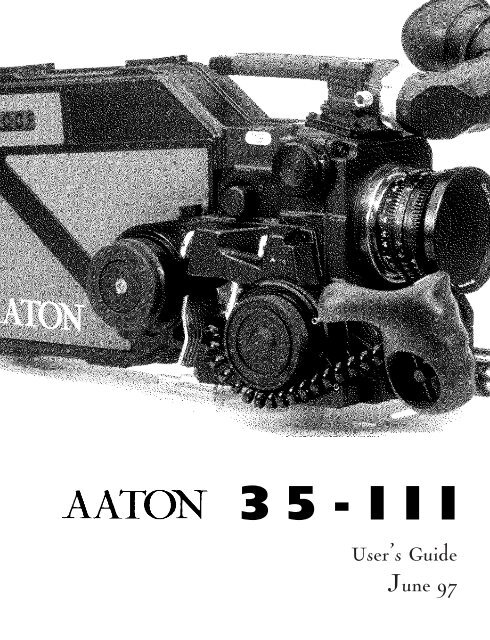
<strong>35</strong>-IIIUser’s GuideJune 97
INTRODUCTION3
The AATON <strong>35</strong>-III User GuideAATON2 rue de la PaixBP300238000 GrenobleFRANCE+33 4 7642 9550+33 4 7651 3491 faxE-mail: support@aaton.comWeb: http://www.aaton.com(c) June 1997 <strong>Aaton</strong> / Grenoble , France.Limitation of LiabilityThe information contained in this manual is distributed without warranty of any kind, express or implied. To the maximumextent permitted by law, <strong>Aaton</strong> and its licensors disclaim any and all warranties, express or implied, by statute orotherwise, regarding this manual, including the fitness for a particular purpose, quality, or merchantability. Under no circumstancesshall <strong>Aaton</strong> or its licensors be liable to the user of this manual or any other person for any incidental, special,or consequential damages resulting from the use of this manual or the operation of the equipment described therein,whether arising out of breach of warranty, breach of contract, or otherwise. Under no circumstances shall <strong>Aaton</strong> or itslicensors be liable for any damages arising out of the operation of the equipment described in this manual, whether operatedin a manner which is consistent with or contrary to the instructions contained therein, for physical abuse or misuseof the equipment. No oral or written information or advice given by <strong>Aaton</strong> or its licensors, their respective employees,distributors, dealers, or agents, shall create any warranty. <strong>Aaton</strong> and its licensors further disclaim any and all warranties,express or implied, by statute or otherwise, regarding this manual, including the fitness for a particular purpose, quality,or merchantability, regarding the equipment described in this manual, and in no event shall <strong>Aaton</strong> or its licensors beliable for any damages, including but not limited to incidental, special, or consequential damages, arising out of the useof the equipment, or any exposure of motion picture film used in the equipment.4
TABLE OF CONTENT1 GENERAL OVERVIEWFront View 12Rear View 13Battery Side 14Motor Side 15LCD Control Panel - Quick Reference 162 THE CAMERA BODY2.1 Lenses 20Arri PL Lens Port 20Installing the Lens 202.2 Viewing System 20Viewfinder Options 20Installing the Extension Finder 21Viewfinder Tension Adjustments 22Adjusting the Diopter 22The Eyepiece Shutter 23Adjusting the Viewing Horizon 23Viewing Screen 23Changing the Viewing Screen 24Adjusting the Viewing Screen 252.3 Mirror Shutter 25Concept 25Adjusting the Shutter 262.4 Film Gate and Pulldown Claw 27Adjusting the Pitch 27The Side Pressure Bar 282.5 Flange Focal Distance Adjustment 28Concept 28Polishing a Spacer 28Changing a Spacer 29Adjusting the Viewing Screen 29Flange Focal Distances 295
TABLE OF CONTENTMenu Operations 423 THE MAGAZINEConcept 48Pressure Plate System 48The Gate Plate 48The Picture Plate 48Loading 49First Step, in Daylight 49Loading, in the Dark 50Adjusting the Loop 514 THE AATON SYSTEMCamera Configurations 5615mm Front Rods 56Sliding Bridgeplate 56Handgrip 57Mounting the Handgrip 57Handgrip On/Off Functions 57Handgrip Adjustment 58Tripod Use 58Shoulder Operation 58Carrying Handle 593/8 Accessory Screw 59Mounting from the Carrying Handle 59Tape Measure Hook 59Transport 60Extreme Conditions 60Cold Weather 61Warm Weather 617
5 CLEANING5.1 Lens 64Lens Elements 64Lens Exterior 64Mounting Surface 645.2 Body 64Exterior 64Mounting Surfaces 65Camera Gate 655.3 Viewing System 65Viewing Screen 66Eyepiece 66Viewfinder 665.4 Magazine 66Exterior 66Pressure Plates 66Interior / Film Path 676 SUPER<strong>35</strong>6.1 Super<strong>35</strong> 70The Format 70When to Shoot Super<strong>35</strong> 706.2 Super<strong>35</strong> Field Conversions 71Changing the Viewing Screen 71Shifting the Viewfinder 71Shifting the PL Lens Port 71Shifting the Video Assist 727 3-PERF FORMAT7.1 Concept 767.2 The AATON <strong>35</strong>-III 3-Perf Camera Body 768
TABLE OF CONTENT8 AATONCODE8.1 Concept 808.2 The Internal Clock 808.3 OriginC plus MasterClock 818.4 Initializing <strong>Aaton</strong>Code in the Camera 81Using the OriginC plus - Recommended Method 82Using an External SMPTE Device 828.5 Monitoring and Maintaining <strong>Aaton</strong>Code 83Monitoring <strong>Aaton</strong>Code with OriginC plus 83Maintaining <strong>Aaton</strong>Code without OriginC plus 838.6 GMT1 Smpte Generator 848.7 The Camera’s Assistant Duties 84Checking the Diodes 84Setting the ASA 859 TECHNICAL SPECIFICATIONSList of Specifications 88Connector - Pin Attributions 89Viewing Screens 909
1GENERAL OVERVIEW11
123456789101.1 FRONT1 Eyepiece2 Friction Adjusting Ring adjusts the tension of the eyepiece swivel3 Diopter Set Ring adjusts the diopter setting of the viewfinder to the operator’s eye4 Lateral Lock Knob locks the lateral position of the viewfinder5 PL Lens Port6 CCD Control Unit7 CCD Friction Ring8 Lens Locking Ring9 Wooden Handgrip10 15mm Front Rods12
212223242526272829301.3 BATTERY SIDE21 Carrying Handle22 Base of the carrying handle and viewing system block23 Guiding Pin for the magazine24 Amph9 Connector connects the CCD unit to the camera body25 Cap covering the viewing screen holder26 Magazine Connector27 Coupler allows for the handgrip attachment28 Guiding Grooves for the Magazine29 LED Indicators30 Run/Test Switch provides camera Run and half frame inching14
GENERAL OVERVIEW313233<strong>35</strong>3634373839401.4 MOTORS SIDE31 Eyepiece Shutter blocks light when operator’s eye is away from the viewfinder32 Lemo6 Connector33 Lemo8 Connector34 Led Indicators<strong>35</strong> Handgrip Run/Test Switch provides camera run and full frame inching36 Lemo2 Connector37 Magazine’s Take-up Core Motor38 Handgrip T-Screw39 Mag Release Lever40 Magazine’s Sprockets and Camera Pulldown Claw Motor15
1.5 LCD CONTROL PANEL - QUICK REFERENCETime speedTestVARISO / BattSYNCRunSETISOIN SHOW MODE24’ - 080 Camera speed and Remaining footage (default mode)ISO = 100 Film ASA (1 x Batt/Iso)Batt = 10’4 Battery voltage (2 x Batt/Iso)MAG =0071 Magazine number (3 x Batt/Iso)Sp = 27’454 Camera Speed (1 x Speed)Ela = 042 Elapsed footage during last take (2 x Speed)22=32=54 Hours=minutes=seconds in <strong>Aaton</strong>Code (1 x Time)95-03-25 Year-Month-Day in <strong>Aaton</strong>Code (2 x Time)123456 Production ID in <strong>Aaton</strong>Code (3 x Time)2321 Equipment number in <strong>Aaton</strong>Code (4 x Time)IN SET MODESp =2 4’ Adjusting a preset speed (SET, 1 x SYNC, toggle SYNC or use Jog)Sp = 27’454 Adjusting a specific speed (SET, 1 x VAR, use Jog)Et Speed controled by external speed device (SET, 2 x VAR)Phase Phase Adjusting (Camera running,SET, 2 x VAR, use Jog)ISO = 100 ASA Setting (SET, 1 x ISO, toggle ISO or use Jog)WARNINGSLo SpdCamera has not yet reached the selected speedLo Batt Battery is too low (below 10V)LoopFilm loop is too smallScratchSomething is wrong in the magazineEmptyNo more film in the magazineUnadjust Please check page 3916
2THE CAMERA BODY19
2.1 LENSESThe AATON <strong>35</strong>-III’s flexible lens mounting system allows for the use ofa wide variety of <strong>35</strong>mm lenses.Flange focal distance.Refers to the critical distancefrom the lens seat to the filmplane. With the PL port, theprecise FFD of the AATON<strong>35</strong>-III is 52mm -40 to -50microns as measured with adepth gauge in the lens port.With the PV port, the FFD is57.15mm -60 to -70 micronsIt is recommended that thesetolerances be checked andmaintained by a qualified technician.The combination ofFFD and back focus distanceof a lens directly affects precisefocus and overall image sharpness.Make sure these criticalmeasurements are strictlyupheld. When using an unfamiliarlens for the first time,check that the eye focusmatches the tape-measuredfocus marks on the lens, and/orshoot a focus test.2.1.1 ArriPL Lens PortThe ArriPL lens port is the standard mounting system deliveredwith the AATON <strong>35</strong>-III and allows the use of all <strong>35</strong>mm ArriPLmounted motion picture lenses. PL lenses adaptors are available forArri standard and Arri bayonet mounted lenses. This lens port isideal for rental facilities, where a mounting system compatible withother manufacturer’s <strong>35</strong>mm cameras is often desired.If you need to get a <strong>Panavision</strong> or Nikon mount, please contact acertified <strong>Aaton</strong> technician.2.1.2 Installing the LensTo install the lens on the camera body, turn the outer locking ringcounter-clockwise. If the port cap is on, remove it. Align the fourprotruding flanges on the lens with the four corresponding cutawaysin the locking ring and insert the lens into the camera port so thatits flanges rest evenly against the lens seat. Tighten the locking ringby turning clockwise until the lens is secured in place and the lockingring is firmly set. Make sure the locking ring is tight enough sothat it cannot be inadvertantly unlocked.VIEWING SYSTEM2.2.1 Viewfinder OptionsThe viewfinder is designed to be fully orientable, providing left orright side viewing and upright image in any position. The viewfindercomes equipped with a standard short eyepiece that can be usedfor handheld and tripod-mounted operation. For more comfortabletripod and studio applications, the standard extension finder(200mm) can be fitted in place of the short eyepiece. With an Elemak or20
THE CAMERA BODYMitchell type dolly, or in situations requiring additional reach, thehyperlong (400 mm) finder, which is twice as long as the standardextension finder, can be used.The <strong>Aaton</strong> hyperlong finder integrates as a standard feature a heatingsystem designed to fight mist. A heating system kit is also availablefor the standard eyepiece.2.2.2 Attaching the Extension FinderIn order to use an extension finder on the AATON <strong>35</strong>-III, the standardeyepiece must first be removed To remove the eyepiece, locatethe eyepiece lock ring, marked a in the image below. Rotate counterclockwiseuntil the ring reaches its stop and gently pull off the eyepiece.To install the extension finder, locate the protruding guideThe Pechan PrismIn order to provide a fullyorientable upright image, the<strong>Aaton</strong> viewfinder incorporatesa Pechan prism assembly, whichis actually comprised of twotriangular prisms sandwichedtogether. On some viewfinders,depending of the constructionof this prism, rotation of theeyepiece a full 360°will causethe image in the finder to shiftslightly left or right.After attaching an extensionfinder, if the image in the finderappears to have shiftedslightly, rotate the finder 360°and choose the preferred centeredimage.dcba21
pin on the seat of the viewfinder and align the pin with the hole inthe flange of the finder. Make the flange to the seat of the viewfinderand tighten the lock ring until it is set firmly in place. Duringthis procedure, you will notice that the extension finder needs toface 180° away from the operator’s eye to be installed on the viewfinder.Because of its optical construction, this is completely normal.After installation, rotate the finder 180° to regular viewing position.2.2.3 Viewfinder Tension AdjustmentsThe large knurled knob at the base of the left/right lateral movementpoint (B) locks the lateral positioning.The friction adjusting ring, located behind the eyepiece lock ring,can be used to adjust the tension of the eyepiece swivel, dependingon the operator’s preference and the viewfinder being used.When using the standard eyepiece, tension should be relatively lightto allow for movement with a moderate amount of pressure.When using a standard extension finder, tension should be increasedto hold the additional weight of this finder in place.To adjust the tension of the swivel, loosen the steel knurled screw(C) located on the friction adjusting ring. Hold the eyepiece in place,rotate the adjusting ring slightly and retighten the screw; 1/8 of aturn, at first, will have an effect. To increase the tension of the eyepieceswivel, rotate the adjusting ring clockwise; to decrease the tension,rotate the adjusting ring counter-clockwise.2.2.4 Adjusting the DiopterBefore shooting, the diopter setting of the viewfinder should beadjusted to the operator’s eye. To set the diopter, locate the diopterset ring (D) in front of the carrying handle at the top of the viewfinder,and loosen the small knurled knob. Look through the viewfinder,rotate the diopter set ring until the edge of the cross-hair is atits sharpest point and retighten the knob. It is recommended that,for easiest setting, this adjustment be performed with the port coveroff and no lens on the camera.Notice that the diopter set ring is engraved with numbers and dots22
THE CAMERA BODY-use this reference to quickly recall your particular setting whenmore than one person will be looking through the viewfinder.If a corrective lens is required, one can be fitted in the recessed areaof the eyecup ring of both the standard eyepiece and the extensionfinder.2.2.5 The Eyepiece ShutterIn order to avoid light seepage through the viewfinder, the eyepieceshutter must be closed any time the camera is running film and theoperator’s eye is away from the viewfinder.Locate the black wheel under the base of the carrying handle. Toclose the eyepiece shutter, turn this wheel counter-clockwise. Toopen it, turn the wheel clockwise.2.2.6 Adjusting the Viewing HorizonIf the rotation of the image seen through the camera’s viewfinderdoes not exactly match what is seen through the naked eye, there isa fine adjustment that can be made to the image’s relative horizon.Locate the small slotted screw located on the underside of the viewfinderinside the eyepiece lock ring. Notice that the screw travels inan elongated cutout. Loosen the screw one turn and, while lookingthrough the viewfinder, move the screw within its cutout in order toadjust the horizontal rotation. When the images seen through yourleft and right eyes coincide, lock the screw.Checking your viewinghorizonthere is a simple means ofdetermining whether adjustmentof the horizon needs tobe made. Mount a zoom lensonto the camera and rest thecamera on your shoulder in astandard handheld position.Look through the viewfinderwith your right eye while alsokeeping your left eye open.Compose a frame that includesvertical or horizontallines (a window frame forexample) and adjust the zoomon the lens so that the focallength of the lens generallymatches what you see withyour left eye.Ignore the viewing screen markingsfor the time being anddetermine whether the rotationof the image you see throughthe viewfinder matches whatyou see with your left eye. If itdoes not, then a find adjustmentmay be necessary.2.2.7 Viewing ScreenThe AATON <strong>35</strong>-III utilizes an interchangeable viewing screen (or“ground-glass”) system which allows the cinematographer to installthe screen which best suits his particular application. <strong>Aaton</strong> offers12 viewing screens as standard (see section Viewing Screens in theTechnical Specifications chapter).Custom screens can also be manufactured upon request. Contactyour local <strong>Aaton</strong> representative for details.2.2.8 Changing the Viewing Screen23
post-itscreenThe viewing screen is designed to be easily removed by the user forthe purpose of interchanging or for cleaning. To remove the screen,first remove the port cap. Remove the battery and clear the mirrorshutter so that it is positioned safely inside the body by rotating atthe base of the shutter with your finger. Look into the port andlocate the screen directly above the aperture opening. To operate,use a piece of Post-it, that will take the viewing screen without dirtyingit. Put the Post-it on your forefinger, the sticking part of itfacing up. Smoothly put your finger on the viewing screen, andremove it.To reinstall the screen, look into the port and locate the right andleft lip of the viewing screen holder. The grounded side of the viewingscreen should face down. Proceed as before, with a piece ofPost-it on your finger.2.2.9. Adjusting the viewing screen :The image focus on the viewing screen (or “ground-glass”) shouldmatch the lens barrel focus mark and the focus on the film. Beforeadjusting the viewing screen, be certain that the flange focal distance24
THE CAMERA BODYof the camera is set according to the manufacturer specifications. 52mm ,57.15 mm and that the lens used is correctly adjusted ; thiscan be determined by the use of a collimator. It is preferable to use a“wide angle lens” i.e. : less than 25 mm. To proceed, you must firstunscrew and remove the circular Cap located on the upper side ofthe rectangle plate, above the battery locking screw. Inside the accesshole, locate the screen holder that you can unlock by turning itsAllen screw counterclockwise. Set your focusing chart at a measureddistance. Set the focus mark of the lens at the exact same distance (Adjust the diopter ! ) you can, now, focus theground-glass, moving the holder up or down by turning the <strong>Aaton</strong>two pins tool. Lock the Allen screw. Double check the focus of theviewing screen using the focus ring of the lens. If the image is stillnot sharp, proceed again.2.3 MIRROR SHUTTER2.3.1 ConceptThe reflex mirror shutter is designed to provide an optical path tothe viewfinder while the claw movement advances the film to thenext frame.The shutter features a four-position user-adjustable opening.• Standard180° for filmingunder standard 60 Hz HMI lighting at 24 fpsor under standard 50 Hz HMI lighting at 25 fpswithout flicker.• 172.8° for filmingunder 50 Hz HMI lighting at 24 fpswithout flicker.• 150° for filmingunder 60 Hz HMI lighting at 25 fpsAlways Remove theBatteryEach time you need to go insidethe camera body, you mustfirst remove the battery. If, bymistake, the camera starts runningwhile you finger is rotatingthe mirror shutter, themechanism of the camera bodycould be seriously damaged.25
without flicker.• 144°to minimize the roll bar while filmingNTSC broadcast monitor at 24 fps.2.3.2 Adjusting the shutterTo adjust the shutter opening, unscrew the shutter tool marked“Sh” located in the hollow at the rear of the camera’s carrying handle.Make sure that the battery is off the camera and remove the portcap. Locate the tool guiding hole to the lower right of the inside lensholder. Gently rotate the shutter at its base with your finger untilthe brass driving gear is centered underneath the tool guiding hole.Insert the shutter tool through the guiding hole and into the brassgear. Rotate the tool until the appropriate notched shutter setting isreached ; turning counter-clockwise will reduce the shutter opening,turning clockwise will increase the opening.When setting the opening to 172.8°, 150° or 144°, a shutter bladeindicating these settings will be visible from behind the left edge ofthe mirror. Make sure the white line to the immediate right of the172.8°, 150° and 144° markings meet the left edge of the mirror.tool guiding hole26
THE CAMERA BODYWhen the adjustment is complete, remove the tool and store back inthe hollow of the carrying handle.2.4 FILM GATE AND PULLDOWN CLAW2.4.1 Adjusting the PitchTo adjust the pitch, use the tool (Ref 09.203.65) located at the rearof the camera carrying handle.Looking at the camera with the lens port facing you, locate thesmall opening situated between the two camera front rods, closer tothe left rod. Using the tool, you can undo the Allen screw retainingthe opening cover. Insert the tool inside the opening. You will "feel"a screw that you will turn counter-clockwise until it stops. The lengthof the pulldown is now at its maximum.Put the loaded magazine on the camera, and keeping the tool inposition, inch and run the camera. The camera will run with a "clickingnoise", due to the perf being hit by the claw. Turn the toolclockwise until you reach a more pleasant noise, like a loud "purring".If you go too far, you will hear one "clack" noise indicatingthat the claw lost a perforation. If more than one "clack" is heard,the camera display will show "LOOP".Once you reach the proper setting, it is recommended to turn thetool counterclockwise, approximately 20º, to accomodate any variationof the film pitch that occures between different film stocks orunder humid or hotweather conditions. To do this adjustment, usethe film stock you are most likely to use.2.4.2 The Side Pressure BarThe film gate also features a side pressure bar which is recessed intothe claw-side rail at the point of image exposure to insure maximumlateral stability.2.5 FLANGE FOCAL DISTANCEADJUSTMENT27
2.5.1 ConceptFor a few years now, <strong>Aaton</strong> has inserted a spacer between the lensport and the camera body. This thin (0.3mm) metallic ring is responsiblefor the precise distance between the lens port seat and thefilm plane called the flange focal distance (FFD), and therefore it isalso mainly responsible for the sharpness of the images.In order to change the FFD of the AATON <strong>35</strong>-III, simply changethe spacer, and only the spacer. Do not polish any other surface, orinsert anything else between the lens port and the film plane. Forfine adjustment of the FFD, order some aluminium spacers(0.<strong>35</strong>mm) from your <strong>Aaton</strong> agent, and then safely change the FFDof your camera.2.5.2 Polishing a SpacerIn order to fine-adjust the thickness of a specific spacer, <strong>Aaton</strong> carriesa specific tool (ref <strong>35</strong> 310 32) designed to hold the spacer firmlyand evenly against polishing paper. When polishing a spacer, alwayswork on a perfectly flat worktable or stone, and be sure to firmlyhold the tool.2.5.3 Changing the SpacerThe spacer is placed between the PL lens port and the camera body’stitanium base. First, remove the lens locking ring: screw two or threeturns its stop (placed on the bottom, inside the PL port), and turnthe ring counterclockwise. Remove the PL port by unscrewing its 6screws. Then gently remove the aluminium spacer .Once you have placed a new spacer, install the PL port, then thelenses locking ring, and do not forget to unsrew two or three turnsthe locking ring stop.2.5.4 Adjusting the Viewing ScreenBecause you have changed the distance separating the base of thelens and the camera body, the image on your viewing screen mightnow appear to be less sharp than usual. Most likely, you may need28
THE CAMERA BODYto readjust the precise focus of the viewing screen. Refer to the 2.9section of this chapter to proceed.2.5.5 Flange Focal DistancesHere are the flange focal distances for all the lens ports available forthe AATON <strong>35</strong>-III. Remember that these distances are automaticallyshorter by 0.3mm than the indicated ones (because of the neededspacer)2.6 MAGAZINEMount Référence FFD Diameter AdjustmentArriflex (PL) <strong>35</strong> 340 30 52.00 mm 54.00 mm -40 / -50 microns<strong>Panavision</strong> (PV) <strong>35</strong> 330 30 57.15 mm 49.50 mm -60 / -70 micronsNikon (Ni) <strong>35</strong> 360 10 46.44 mm 43.53 mm -40 / -50 micronsThe <strong>Aaton</strong> magazine holds 400ft (122m) of <strong>35</strong>mm film, which represents4’28’’ shooting at 24fps in <strong>35</strong>mm 4-Perf, and 5’26’’ shooting at24fps in <strong>35</strong>mm 3-Perf.2.6.1 Installing the MagazineTo install the mag, situate yourself at the rear of the camera body,battery side. Do not forget to remove the aperture plate cover.Place your left hand underneath the magazine while your right handis firmly holding it at the midway point of its rear. Rest the nose ofthe magazine on the camera base, hold the camera body with yourleft hand while pushing the mag in the bottom dovetail and into theaperture area with your right hand. Make sure that the top of the"nose" of the mag is parallel to the camera carrying handle as youguide the mag in place. Push firmly and evenly until you feel andhear that the mag snaps against the aperture area. The mag noseshould be pressed against the camera body's rubber seal. This operationshould be done without having to force the mag into position.29
2.6.2 Removing the MagazineTo remove the magazine, situate yourself at the rear of the camerabody, battery side. Place your right hand palm on the camera takeupmotor and pull the mag lock lever towards the rear of the camerawith your fingers.The mag will be toward the rear of the camera. The mag is now freeto be pulled offthe camera, using both your hands.2.7 POWERThe AATON <strong>35</strong>-III body requires only 12 volts for all aspects of operation.One standard <strong>Aaton</strong> on-board (12V, 1.8 Ah, rechargeable, nicad)will power the camera, CCD and accessories which are connected to thebody’s accessory inputs (such as zoom controls, speed controls, etc.)through a standard 4 pin XLR connector. One 1.8 ah on-board batterywill run 7-8 magazines on the AATON <strong>35</strong>-III, without CCD andaccessories. With accessories in use, this number will decrease.2.7.1 Installing the Battery on the CameraThe on-board battery fits above the LCD conrol panel. In order toinstall, loosen the black knurled screw approximately four or fiveturns. Push the battery evenly onto the XLR4 connection of the30
THE CAMERA BODYbody. When snug, tighten the knurled screw onto the battery tab tohold it in place.When running <strong>Aaton</strong>Code, get into the practice of having a freshbattery on hand before removing the one from the camera. Even alow battery that no longer runs the body (below 10V) will haveenough voltage to keep accurate time counting.Thanks to a super capacitor built into the camera base you will havea full minute to change the battery before time is lost. After replacingthe battery, confirm that time is still counting by checking thecontrol panel.2.7.2 Battery ChargingThe <strong>Aaton</strong> on-board can be recharged with an appropriate 12Vnicad battery charger.For the best results, use a microprocessor-controlled charger or astandard trickle charger with a charging output of at least 200ma,both of which prevent of the overheating and mistreatment of yournicad cells. Always follow the specific guidelines of the chargermanufacturer. You can use the <strong>Aaton</strong> Chr1, designed to charge twostandard batteries in 6 hours, without any risk.Beware of older, timed chargers manufactured when 1.2 and 1.4ah31
atteries where the norm; these chargers where most likely rated forthe lower amperage batteries of that time and will consistentlyundercharge the higher rated nicad cells of today.Nicad Battery TipsFollow a few simple rules toinsure the long life of yournicad cells:• Allow the battery to runthrough their normal cycle ofcharging and use. Avoid toppingoff partially full batteries.Once every few months,discharge cells to 8-10V usinga standard discharger to minimizetheir memory.• Do not rapid-charge yourcells more than necessary, asthe added heat will eventuallyshorten their life span. Insteadrecharge batteries at a normalcharging rate when your scheduleallows.• If your batteries will not beused for long periods of time,always store them in a cool dryenvironment fully charged.2.7.3 Other Power OptionsSince the AATON <strong>35</strong>-III power input is a standard 4 pin XLR type,a great varitey of 12-14 volt sources can be used to power the camera.This includes AC power supplies, battery blocks, lithium cellsand car batteries.Get into the habit of carrying a standard XLR4 powercable in yourpackage in case an alternative power source is needed.Regarding AC power supplies, it is recommended that the unit youuse be at least 5 A and 25 W. Before connecting any non-standardsource, always make sure that the pin configuration of the unit iscorrect. See the Technical Specifications chapter of this manual fordetails for proper wiring.2.8 MOTORThe tri-phase samarium design of the AATON <strong>35</strong>-III provides lowpower consumption and improved stability at high speeds. Thebody is capable of speeds between 3 and 40 fps with a standard12V battery.2.8.1 Camera SpeedsThe AATON <strong>35</strong>-III provides boths preset crystal speeds (in syncmode) and specific crystal speeds (in variable mode) in .001 increments,all accessible from the LCD control panel.Available preset speeds consist of 6, 12, 18, 23.98, 24, 25, 29.97and 30. The preset speed selector (SYNC) allows for quick access tothese frequently used speeds.If any other speed is desired, or if the camera speed must match thefrequency of a monitor to eliminate a roll bar, the specific speedselector (VAR) should be employed. The specific speed selector32
THE CAMERA BODYenables the body to run at any speed between 3 and 40 in .001 frameincrements. A phase adjustment of the variable speed is accessiblefrom the VAR selector and jog wheel.The camera speed can also be adjusted while the camera is runningin either sync or variable mode. For more information on thesespeed functions, refer to section LCD Control Panel and Jog of thischapter.2.8.2 Using External Speed DevicesThe AATON <strong>35</strong>-III can be driven externally from devices such asfilm/video synchronizers, speed aperture computers and externalspeed controls. In these situations, the camera VAR selector must beset to Et. If such a device is connected and the selector is not set toEt, the camera will run at the speed indicated on the display.Keep in mind that, with certain manufacturer’s speed controls, itmay be possible to run the camera at speeds higher than the 40 fpsfactory limitation. Overcranking in such a way, however, will increasemechanism wear, increase noise and compromise image registration.<strong>Aaton</strong> urges to avoid such usage at all cost and will not be responsiblefor the resulting damage that will occur. This top speed capof 40 fps has been designated by <strong>Aaton</strong> because it is the limit atwhich the camera can run safely without any adverse effects on itsmechanics.2.8.3 Electronic InchingThe inching function of the motor is accomplished electronicallyand can be accessed in a number of ways.From the HandgripThe wooden handgrip switch, by way of the lemo2 connector, providescamera run and full frame inching for single frame operationand loop situating.From the LCD Control PanelThe run/test switch, besides the LCD control panel, not only runs33
the camera, but provides half frame inching for gate inspection andloop situating when installing a fresh mag.From a Remote CableThe Lemo2 connector, as well as Lemo6, Lemo8 and Amph9 accessoryconnectors, provide the capability of using a remote on/off witheither a half-frame or full-frame inching function.2.8.4 Single Frame OperationWith the use of electronic inching switch via the wooden handgripor a remote cable, the AATON <strong>35</strong>-III can be used as a simple intervalometerfor single frame operation. Each frame is 1/4 sec exposure.2.9 LCD CONTROL PANEL AND JOGThe AATON <strong>35</strong>-III utilizes a straightforward and intuitive controlpanel structure in conjunction with a small jog wheel to access andadjust all operator functions.2.9.1 The <strong>Aaton</strong> JogLocated to the immediate right of the LCD control panel, <strong>Aaton</strong>Jog is a small wheel designed to simplify many user functions. Whenused in conjunction with the contol panel the jog allows for quickadjustment of some of the otherwise time-consuming parameters(such as the setting of a precise 5-digit speed or a film short end).2.9.2 Understanding the Control PanelThe control panel consists of a LCD display and four buttons toaccess information. The control panel operates in two modes: Showand SET. To show a parameter without adjusting, go directly to oneof the black function buttons to view relative information. To set aparameter, first press the white SET button, then go to the appropiatefunction. Information is changed by either toggling that but-34
THE CAMERA BODYton ot by rotating the jog, depending on the parameter. PressingSET afterwards (or waiting for 7 seconds) will enter your selection.Capped text (SYNC, VAR, ISO) refers to those functions adjustablewhile in the SET mode; standard text (Speed, Time, Iso/Batt) refersto those functions accessible directly in the default Show mode.Note that, while viewing a Show function on the control panel, anyinactivity longer than 10 seconds will revert the display back to itsdefault mode (speed and remaining footage). As mentioned previously,any break longer than 7 seconds while in SET mode willautomatically enter the last selection.The following parameters can be accessed from the LCD controlpanel in conjunction with the jog. For more concise information seethe table in the System Features and Controls chapter of thismanual.2.9.3 <strong>Aaton</strong>CodeAs a standard feature the AATON <strong>35</strong>-III is equipped with the capabilityof recording <strong>Aaton</strong>Code in-camera time. TimeCode informationis exposed onto the film by optical projection of seven microdiodesinto the gate to the left of the aperture opening. Thesemicro-diodes flash rapidly to form the code as the film rolls throughthe gate between exposures.<strong>Aaton</strong>Code is initialized in the camera, in ASCII or SMPTE form,through the Lemo5 connector located to the righ of the LCDcontrol panel. For the most straightforward and reliable communication,OriginCplus, <strong>Aaton</strong>’s masterclock, comparator, and SMPTEgenerator device, should be used.If <strong>Aaton</strong>Code has been initialized in the camera, press button Timeto view timecode information. Toggling button Time will displayhours/minutes/seconds, then year/month/day, then the six-digit productionID, then the camera’s equipment #, in that order.2.9.4 ASA SettingWhen using <strong>Aaton</strong>Code in the AATON <strong>35</strong>-III, the ASA(ISO) settingmust be adjusted to the exposure index of the film stock being<strong>35</strong>
Force Processing and the<strong>Aaton</strong>Code matrixRegardless of the situation,always set the ASA selector tothe actual exposure index ofthe film. If you know beforehandthat your footage will bepushed or pulled, don't worryabout compensating for thesake of the precise exposure ofyour timecode matrix. Thematrix is resistant enough tohandle exposure variances ofone and a half stops or more ineither direction.Changing Speeds whileRunning the CameraAny camera speed, whetherpreset or specific, can be changedwhen the camera is running.To do so, run the camera,then follow these simple steps:• Operating under a presetspeed (in sync mode), pressSET, then SYNC, then use thejog wheel to choose a higher orlower stepped speed.Under a specific speed (invariable speed), press SET, thenVAR, then use the jog to rampthe speed higher or lower in.001 frame increments.used. The ASA/ISO selection will insure that the timecode matrixrecorded on the edge of the film in the gate will be exposed at anappropriate and useable level.If <strong>Aaton</strong>Code is not running in the camera, the setting of theASA/ISO will have no effect.Press button Iso/Batt twice to view the ASA selection.Press SET then button ISO, to adjust the ASA setting. Make yourselection between 25 and 1000 ISO by toggling ISO or by rotatingthe jog wheel.If the ISO selector is adjusted while the camera is in test or runposition, the correction will not take place until the next camerastart.2.9.5 Battery VoltagePress button Iso/Batt to read the voltage of the camera’s power source.Notice that if the camera is running and button Iso/Batt is pressed,the control panel will read and display the voltage under load.2.9.6 Magazine NumberAs soon as a magazine is installed in the camera, you can read isnumber ID by pressing Iso/Batt three times.2.9.7 Camera Preset SpeedThe default mode of the control panel will automatically display thecamera speed selection, whether it be in sync or variable mode,when the camera is powered but not running. When the camera isturned on, the actual running speed to the .01 frame is displayed.To adjust the preset speed, press SET, then button SYNC. Makeyour selection of stepped crystal speed between 6 and 30 fps bytogling SYNC or via the jog wheel.2.9.8 Camera Specific SpeedTo choose a specific speed press SET, then VAR. Make your selectionof any .001 incremented crystal speed between 3.000 and40.000 fps via the jog.36
THE CAMERA BODYTo set the camera to be driven from an external source (such asfilm/video synchronizer or external speed control), press SET, thenVAR twice. Et will be displayed, indicating that camera is set inexternal mode.2.9.9 Speed PhasingThe phasing of the variable speed can be set to eliminate a roll barwhile filming a monitor. Operate first with no magazine on thecamera, because you first need to synchronise the camera speed tothe monitor frequency. Run the camera. Press SET, then VAR once,turn the jog, until the roll bar seems stable on the screen. Press SETto enter. Stop the camera, and then install a magazine. Run thecamera. Press SET, then VAR twice. Look through the camera at themonitor and turn the jog until the roll bar is out of view. Press SETto enter.2.9.10 Remaining FootageThe control panel will display the footage remaining any time thecamera is running with a magazine on. The displayed footage is calculatedby the magazine itself: it is determined by the measure of thefeed core speed. To modify the footage measurement unit, pressISO, then TEST and then ISO again to modify.2.9.11 Elapsed FootageWith the camera stopped, press Speed twice, to view the elapsedfootage of the previous camera run. With the camera running pressSpeed twice to view the elapsed footage of that particular take. Thedisplay will revert back to its default mode (speed and remainingfootage) after 10 seconds.2.9.12 Camera Software Version NumberIf you need to know the software version number your camera isequipped with, proceed as follows. Unplug the battery from thecamera. Put the camera on Test mode. Then, while installing thebattery, watch the LCD control panel carefully. During one secondit will display something like: T4 V2.08, indicating that you own aDisplaying a 5 Digit SpeedIf the AATON <strong>35</strong>-III is set to avariable (5-digit) speed, thecontrol panel will only displaythat speed to the .01 digit.Keep in mind, the display willnot round off the speed, butsimply leave off the last digit.For example, if the 5 digitspeed of 23.976 is entered, thecontrol panel will display23.97, not 23.98.Remember… VariableSpeed for PhasingKeep in mind, the speed phasefunction of the control panelwill only operate when avariable speed is initially selected.When shooting 29.97, forexample, be sure to choose thespecific 29.970 instead of thepreset 29.97 if you plan toincorporate the phase functionfor that particular shot.37
<strong>35</strong>mm 4-Perf camera, working with the software version number2.08.2.9.13 Total Footage RecallTo find out total footage run through the camera since manufactureinstall, hook up a battery onto the camera body, press SYNC andflip the switch to TEST. The footage displays in thousands ofimages.2.9.14 WarningIf for some reason the camera loses its programming parameters,“UNADJUST” will flash regularly. leaving the camera functionning.The TCXO then uses default frequency adjustment, insuring aTimeCoding precision of 10 -4 instead of 10 -6 .2.10 LED INDICATORSThe AATON <strong>35</strong>-III utilizes LED indicators in three locations to conveyinformation: in the viewfinder and on both left and right sides of thecamera body.2.10.1 Position and Meaning of the Diodes• Two yellow diodes, placed on both right and left sides of the camerabody indicate that the camera is either on Test or on Run mode.• Two red diodes, placed on both right and left side of the camerabody, and a third one, visible from the view finder, display a specialwarning.2.10.2 Camera Test Indicator● Yellow diode is on.●●● Red diode is blinking fast.2.10.3 Camera Run Indicator●Yellow diode is on.❍ Red diode is off.38
THE CAMERA BODY2.10.4 Low Battery Indicator● Yellow diode is on.● ● ● Red diode is evenly flashing.The LCD control panel displays Lo Batt.2.10.5 Low Speed Indicator● Yellow diode is on.●● ●Red diode is blinking fast.The LCD control panel displays Lo Speed.2.11 VIDEO ASSISTThe AATON <strong>35</strong>-III accept 4 different video assist: CD52 PAL, CD52NTSC, CD56 PAl and CD56 NTSC. The CD52 are black & white,and the CD56 are color.The control units for all <strong>Aaton</strong> CCD assists attach quickly to the camera’shousing and can be used with an on-board battery. The video assistmay be used to help the director or operator control their images, or toprepare the video editing, before the telecine stage.The following chapter is mostly dedicated to the CD56, which is <strong>Aaton</strong>’shigh-end model, and is designed to offer high quality, flicker-free colorvideo assist imaging, burn-in windows, Vitc insertion and a frame linegenerator in one integrated system.2.11.1 The CD56 Color CCD AssistYou may use the CD56 color CCD assist in two different ways.In some special situations (if you’re filming in the dark for example),it might be more comfortable to look your images on a monitorthan through the viewfinder. This is why the CD56 is equippedwith a frame line generator: as you can choose the size and positionof the generated frame, the image you see through the viewfinder(which might be in ratio 1.78 or 1.66 for example) can match exactlythe image you see inside the frame on the monitor. Moreover this39
Beware of the high powerconsumption of the videoassistThe CD56, as well as theCD52, is equipped with anOn/Off switch. As soon as youhave finsihed with using thevideo assist, witch it to off.Keep in mind that a CD56needs up to 700 mA to run.Vitc lines• First line is the video timecodeline. Each time you switchon the video assist, the videotimecode is set to 1:00'00'' 00(the last number is the imagenumber). Then as soon as theAATON <strong>35</strong>-III is running thistime is incremented.• Second line is the keycodeline. As the keycode should beread from the film, this linecannot be generated. Only synchonizationand checksum bitsare inserted.• Third line is the audio timecodeline, i.e. all the timecodeinformation of the <strong>Aaton</strong>Codeis inserted here.frame is easier to locate than the viewing screen’s frame. The directorcan then immediatly control his operator’s images.Of course, the video assist was first created to be used in such a way.But, now that video editing (including the virtual video editing)offers new powerfull tools to the editor, the CD56 can be used in adifferent way. The CD56 provides a Vitc lines generator, which arethe dots and lines, usually put above the video image, used by videoediting machines. Therefore, images recorded by the video assistmay be directly used to make a video editing of the film; no need towait for telecine, no need also to have developped the rushes youwon’t use.2.11.2 Installing the Control UnitAll of the CCD assists available for the AATON <strong>35</strong>-III can be easilyattached on the camera body, in a few seconds without the need foradjustment.First locate the video port, above the Lemo 6 connector on themotor side of the camera. Using a Allen wrench, loosen 3 or 4 turnsits small black screw. Remove the plastic port cover. Check that theexposed lens of the CCD video assist is free of dust particles. If40
THE CAMERA BODYnecessary, clean this surface with lens fluid applied with a coton Q-tip. Install the lens into the camera video port. Connect the controlunit cable to the camera body through the Amph9 connector.Connect a BNC cable to the monitor and power the AATON <strong>35</strong>-III. Turn on the toggle switch of the CCD Unit, the yellow diodeshould light. Set the video assist iris wide open, and while looking atthe monitor, move the whole control unit until the viewing screenimage is in focus and square to the monitor. Rotating the unitcontrols the image horizon, pulling or pushing it controls the imagefocus. Tighten the Allen set screw to lock the control unit in position.If the camera lens mount has been shifted from <strong>35</strong> to super <strong>35</strong>,loosen the video tap retaining the screw and refocus.2.11.3 Menu OperationThe CD56 unit contains six operator buttons: up, down, left, rightarrows, menu and exit keys.Press MENU to have the menu displayed.Use arrows to access to the desired parameter.Press MENU to indicate that you want to modify this parameter.Use arrows to adjust this parameter.Press MENU to validatePress EXIT to memorize the new configuration.• StdChoose the video image frequency you need between 24 and 25frames per second. Keep in mind that choosing 24 fps, provides anon standard video signal, that you won’t be able to record.• Color TempDepending on the kind of film you’re using (a film for inside or afilm for outside) the colors it will register will not be the sames. Tohave the video colors closer to the film colors, you can choose between3200K (tungstein) and 5600K (daylight).• DateDate allows you to choose the position of the current date insertion41
42inside the video image. Use the arrows to proceed.•TimeTime allows you to choose the position of the current time insertioninside the video image. Use the arrows to proceed.• CamCam allows you to choose the position of the magazine numberinsertion inside the video image. Use the arrows to proceed.• FrameFrame/Frame On-Off allows you to choose if you want (On) or not(Off) a frame to be inserted in the video image.Frame/Frame Top Left allows you to choose the position of the topleft position of the frame. Use the arrows to proceed.Frame/Frame Botton Right allows you to choose the position of thebottom right position of the frame. Use the arrows to proceed.Frame/Edge allows you to choose between an Edge around the frame,or No Egde.• Phase adjustPhase adjust is designed to move the flicker area outside the videoimage. This function is available only when the CD56 and theAATON <strong>35</strong>-III are running at the same speed (both at 25 fps, forexample). Use the up and down arrows for a first quick phaseadjustment. And then, use the left and right arrows for a fine adjustment.To proceed, run the camera and watch the video monitor.• OptionsOptions allows you to access to a submenu only dedicated to the<strong>Aaton</strong>Code insertion.Options/Screen allows you to choose to insert (On) or not (Off)<strong>Aaton</strong>Code information, which consists of Time, Date, and Equipmentnumber ID.Options/Screen Y/C allows you to choose to insert (On) or not(Off) the Y/C video exit informations.Options/Font allows you to choose the font you need for the charactersto be inserted. Choose 0 for edged characters, 1 for standardcharacters, and 2 for bold characters.• Technical
THE CAMERA BODYTechnical allows you to access to a submenu only dedicated to theVitc lines insertion. These lines are automatically inserted in thevideo image.Technical/XTAL Adjust is a parameter adjusted in factory. Keep inmind that you should never modify it.Technical/VITC Position allows you to choose the position of theVitc lines. Choose between line 16 and line 24.Technical/VITC Parity allows you to select the parity of the Vitclines between Odd and Even. Make sure that your post-productiontools run properly with the selected value.• About the Vitc linesIn order to have meaningful information encoded in the Vitc lines,camera and video need to run at the same speed. If the video is setto run at 25 fps, then the AATON <strong>35</strong>-III should run at 25 fps.And when the video is set to 24 fps, the AATON <strong>35</strong>-III should runat 23.98 fps (this slight variation between these two speeds comesfrom some electronical imperious needs).If the third Vitc line cannot be generated by the CD56, then a (*)appears on the screen. This might occur because of two differentsituations: whether the speeds of the AATON <strong>35</strong>-III and the CD56are different, or <strong>Aaton</strong>Code has not be initialized inside theAATON <strong>35</strong>-III.43
3THE MAGAZINE45
3.1 CONCEPTThe <strong>Aaton</strong> magazine has been designed to be instantly installed orremoved, and to be loaded quickly. In order to have a more compactmagazine, both cores (feed and take-up) shift together during filming.The magazine is driven magnetically from two intermediate drivesconnected to the camera motors; two magnetic wheels on the innerside of the camera body couple with two similar wheels on thethroat of the magazine to transport the film. A magnetic drive systemdecreases noise and power consumption, and prevents mechanicalstress during mis-loads.The magazine handles up to 400 ft (122m) loads of <strong>35</strong>mm filmstock. 400 ft of film is a little more than 4 running minutes at 24fps3.2 PRESSURE PLATE SYSTEMThe magazine features two pressure plates which are located at the frontof the magazine’s nose. When the loaded magazine is attached to thecamera, these pressure plates provide the precise stabilization of the filmduring exposure and transport.3.2.1 The Gate PlateThe long plate, called the gate plate, is positioned at the camera’sgate. Its main function is to stabilize the film as the claw engages thefilm perf between exposures. Proper tension and functioning of thegate plate contribute to reliable transport and quiet operation.3.2.2 The Picture PlateThe striped pressure plate, called the picture plate, is positioned atthe camera’s aperture opening and is designed to hold the film steadyat the point of exposure. Proper setting and functioning of thepicture plate assures the precise focus of each image.46
THE MAGAZINE3.3 LOADING3.3.1 First Step, in DaylightHere you prepare the magazine to receive the film.• Place the magazine on a table, its throat facing left. Unfasten thedoor locks by turning downward and open the door.• You can now choose to have the footage remaining displayed (onthe magazine as on the LCD control panel on the camera body) infeet or meters. The red sliding switch, accessible from the inside ofthe magazine, sets meters on its right, and feet on its left.• With your thumbs, push the two spindles towards the nose of themagazine. This operation is accompanied with a loud clickingsound: don’t be alarmed, this is completely normal.• Unscrew both spindle-locks (if necessary, hold the base of thecores). The spindle-locks are easy to locate: they have the shape of arounded rectangle.• You can now place an empty core on the take-up spindle (the leftone). Check that the core drive pin on the spindle is not caught onone of the core ribs or the roll will not seat properly. Firmly screwdown the corresponding spindle-lock to secure the empty core tothe spindle.Attention! Be sure you have put the core in its correct way. To checkso, imagine that you will have to fit the film in its slot. A whitearrow is engraved on the base of the spindle to help you install itcorrectly.• Release both sprocket pinch rollers (they have the shape of a halfcircle) by rotating them counter-clockwise. Theses rollers should beopened to let the film slide between them and the sprockets.Their half-circles face the nose of the magazine when closed, or facethe chamber of the magazine if they are opened.• Now closely look at the mechanism inside of the magazine. Andmemorize the following diagram and instructions.• Then, put the magazine in a dark room or changing bag.3.3.2 Loading, in the Dark47
• Remove the film from its can and bag.• Place the film roll on the rear spindle. Check that the core drivepin on the spindle is not caught on one of the core ribs or the rollwill not seat properly. Secure the spindle-lock.• Thread two feet of film, making sure it passes outside the top guidingrollers.• Insert the film between the pinch rollers and sprockets makingsure the perforations engage with the sprocket teeth.• Turn the upper and lower pinch rollers clockwise, to close them.• Slide the film in the slot of the take-up core. Rotate this core threeor four turns.• Check that the film is firmly attached and positioned correctlyaround the sprocket wheels.• Close the door, and fasten the door locks by turning them upward.If you cannot close the film door, it means that you have forgottento close one or both pinch rollers.• The remainder of the procedure can be performed in daylight.3.3.3 Adjusting the Loop, in daylightsprocketsprocket pinch rollertake up corefeed core48
THE MAGAZINEOnce the door is closed, you need to adjust the loop.•Place the magazine with its digital display facing toward you andthe magazine nose being to your right. The correct loop size can beadjusted, by using the loop tool delivered with the magazine.•If you cannot insert the tool between the mag pressure plate andthe fim, you need to enlarge the loop. To do so, push the disk marked"push for loop adjust" with your right tumb while holding thefilm against the pressure plate with your right forefinger. Using yourleft hand rotate the upper magnetic wheel clockwise until the looplength allows you to insert the tool.•If you need to reduce the loop length, simply push the disk marked"push for loop adjust" with your right thumb and rotate the uppermagnetic wheel counterclockwise before installing the mag on thecamera. DO NOT FORGET to remove any slack existing betweenthe lower sprocket and the take-up spool. To do so, rotate themagnetic wheel situated at the left of the loop adjusting disk counterclockwise.The wheel should turn smoothly as the film winds on49
50the take-up core indicating that the magazine has been correctly loaded.•You can then install the mag on the camera body.•To engage the film, turn the camera's ON/OFF switch to test positionand off again. If the loop is too short or not properly centeredinto the camera gate, the camera LCD display should show"LOOP". Desengage the magazine, readjust the loop length if necessaryand reinstall the magazine on the camera body.
THE MAGAZINE51
4THE AATON SYSTEM53
4.1 CAMERA CONFIGURATIONSThe AATON <strong>35</strong>-III is designed to be easily converted between the followingtwo accessory configurations:4.1.1 15mm Front RodsThe most versatile and popular configuration for accessorizing theAATON <strong>35</strong>-III, the universal 15mm screw-in front rod system caninstantly accept <strong>Aaton</strong>, Arri, Chrosziel, Petroff and other manufacturers’mattebox and follow focus system.Utilizing the front rod system allows for quick conversion from tripodto shoulder operating modes without the need for reconfiguration.<strong>Aaton</strong> manufactures 50mm and 120mm length rods that screwdirectly into the front housing of the AATON <strong>35</strong>-III under the lensport.The 15mm front rod system is recommended when standard sizelenses and accessories are to be used or when quick conversion betweentripod and handheld modes is necessary.4.1.2 Sliding Bridgeplate54
THE AATON SYSTEMThe AATON <strong>35</strong>-III can also accept standard 15 and 19mm slidingbridgeplates for building the camera system for high-end studiowork. The bridgeplate configuration can accept <strong>Aaton</strong>, Arri, Chroszieland other manufacturer’s mattebox, follow focus and supportequipment that is designed for bridgeplate use.Standard bridgeplates from <strong>Aaton</strong>, Arri and other manufacturers canbe attached to the AATON <strong>35</strong>-III by means of the 3/8-16 tripodrecepticle on the underside of the camera.The sliding bridgeplate system is recommended when large <strong>35</strong>mmlenses and accessories are to be used and when the use of a gearedhead is necessary.4.2 HANDGRIPThe AATON <strong>35</strong>-III body includes a wooden handgrip, short 15mmrods, rod coupler and Lemo2 cable as standard. The handgrip which isdesigned to be used for comfortable handheld operation, can also be usedto provide on/off control on the motor side of the camera while on thetripod.4.2.1 Mounting the HandgripScrew in one 15mm short rod in each of the two recepticles on thefront housing of the camera below the lens port. Slide the couplerover the two rods to the desired location and fasten the center wingnut to secure the coupler in position. Attach the handgrip to thecoupler by mating the starplate on the coupler to that on the handgrip,adjusting to the desired position and fastening the T screw ofthe handgrip. Connect the Lemo2 cable between the handgrip andcamera body to add on/off capability to the handgrip. The Lemo2connector is located on the motor side of the camera, (between thetwo motors), under the Lemo8 and Lemo6 connectors.4.2.2 Hangrip On/Off FunctionsBoth camera run and test functions are available from the handgrip.55
While hand-holding the camera, pressing the rocker switch to theright provides camera run, pressing the switch to the left providestest. Unlike the body switch, the camera test position of the handgripis a momentary switch. Pressing and holding the switch opensthe shutter and advances the mechanism 1/2 frame. Pressing andimmediately releasing this switch advances the mechanism one fullframe at a 1/4 sec exposure time. This function allows the use of thehandrip as a simple intervalometer.4.2.3 Handgrip AdjustmentThe handgrip rotation should be adjusted for maximum handheldoperating comfort. Loosen the T screw and rotate the handgrip atthe star plate until a more comfortable position is found. If a moreextreme repositioning is required, whether it be for reasons of comfortor clearance in certain studio rig configurations, this can beachieved with coupler extenders, spacers and intermediate arms whichutilize the star plate system for adjustment. Ask your agent for aconfiguration that meets your needs4.3 TRIPOD USEIn order to use the AATON <strong>35</strong>-III on a standard tripod, the tripod’squick release plate must be fastened to the underside of the camerabody with its standard 3/8-16 screw. Make sure to use only a quickrelease plate screw provided by the manufacturer; non standardscrews longer than 8mm (1/3’’) can fracture the base casting anddamage the camera’s electronics.4.4 SHOULDER OPERATIONOne of the most attractive features of the <strong>Aaton</strong> system has alwaysbeen its comfort and ease of use in handheld situations.The AATON <strong>35</strong>-III does not require the use of shoulder braces or56
THE AATON SYSTEMadditional padding for handheld operation. The wooden handgrip isattached to the front rod coupler at a slight angle to bring the operator’selbow into his side and increase stability.The system can be completely built off the 15mm front rodswithout the use of a bridgeplate to allow for quick changing fromshoulder to tripod operating modes.4.5 CARRYING HANDLEThe carrying handle of the AATON <strong>35</strong>-III is reinforced to safely accomodateany carrying, operating or mounting operation.4.5.1 3/8 Accessory ScrewThe handle features a 3/8-16 insert to receive accessories such asfrench flags and lightweight monitors. Be sure not to use a 3/8 screwlonger than 11mm (7/16’’); longer screws can fracture the insert anddamage the viewfinder’s optics.5.2 Mounting from the Carrying HandleThe 3/8 insert can also be used to build a plate to undersling thecamera or to configure the rig for Steadicam low mode use. For thisreason, the handle features a long flat top surface that is parallel tothe bottom of the camera.4.5.3 Tape Measure HookThe handle is also equipped with a hideaway tape measure hook,which is positioned between the rods directly behind the 3/8 insert.To use this hook, pull it up and fasten the ring of a standard assistant’stape measure around it; the hook holds the tape measure zeropoint precisely at the film plane.4.6 TRANSPORT57
One often overlooked, yet vital factor in the proper functioning and longevityof your camera equipment is your transportation practices. A fewgood shipping habits can avert potential damage caused by careless messengerservices and airport handling.When shipping and carrying your equipment, it is always goodpractice to break down the package to its basic components wheneverpossible. Ship the body, mags and batteries unattached and individuallypadded. Never, under any circumstances, ship the camerawith a lens attached (especially a zoom lens). Shocks transferredfrom the outside of a case could have disastrous effects to the ultracriticalback focus of a lens and flange focal distance of a camera iftransported as one.Make certain there is ample padding between individual componentsin a case and from the case’s outer edges. Shipping case manufacturerssuggest a minimum of 1 1/2’’ padding between high precisioncomponents such as the camera and lenses. 1’’ of padding isacceptable, however, between some of the more rugged components,such as magazines and batteries. Manufacturers also suggest to allow2’’ of padding between the components and the outside of the case.Choose a case design that, not only meets your shipping and travelrequirements, but allows you maximum flexibility and comfort outin the field. Check with your <strong>Aaton</strong> agent to determine the caseconfiguration that best suits your needs.4.7 EXTREME CONDITIONSCertain precautions should be taken in order to achieve maximumperformances when operating the AATON <strong>35</strong>-III in extreme oradverse conditions.4.7.1 Cold WeatherThe AATON <strong>35</strong>-III features a built-in electronic heating element58
THE AATON SYSTEMlocated in its base which is designed to automatically turn on whenneeded and maintain the claw mechanism at a temperature of 15°F.One of the cold, hard facts of cold weather shooting is the considerablereduction of battery life. Do whatever possible to conserveyour batteries and always carry more than usual. Favor many smallbatteries, such as on-board and lithium cells (which are easier tokeep warm), over large block batteries. Use a powercable so that theon-board battery could be kept in a pocket close to the warmth ofyour body.When filming outdoors, use a standard or heated barney to protectthe camera body from direct contact with the wind and cold. Toavoid condensation inside the mechanism, electronics and lens elements,do not take the equipment indoors or expose it to suddentemperature changes. If and when the equipment must be movedinside, do so by first placing it in a sealed container and let it thawfor a few hours before opening.Always keep your raw stock and loaded magazines above freezingtemperatures at all times during a cold weather shoot.4.7.2 Warm WeatherThe keep the temperature of the camera body down, avoid havingthe camera exposed to direct sunlight for long periods of time byusing a barney, all-weather cover, or some form of shading, like anumbrella.Most importantly, keep raw stock and magazine in a dry cooler, orin the coolest location available.59
5CLEANING61
5.1 LENSLens Cleaning TipsAvoid handling lens tissues onthe surfaces which will contactthe lens. Oil from your handstransferred to the lens surfacewill make an easy cleaning jobtough. Furthermore, neverclean a lens element withoutthe aid of cleaning fluid. Agood number of scratchs onlens surfaces are caused by poorcleaning methods.5.1.1 Lens ElementsThe front and rear surface of your lenses should be inspected regularlyand always kept clean of dust particles, smudges, fingerprints,etc. First, blow off any large particles of debris using an air syringe.Lens elements should then be cleaned using lens cleaning fluid withlens tissue. Apply a few drops of cleaning fluid to a fresh lens tissueor directly to the lens. Wipe the lens in a circular fashion, startingfrom the center and working towards the outter edge. Finish with afresh dry tissue. If some streaking remains, repeat the procedureuntil the surface is sufficiently clean.5.1.2 Lens ExteriorThe exterior of your lenses should be cleaned of dirt and adhesivesas necessary. Use a multi-purpose cleaner or degreaser such as De-Solv-It applied with a Q-tip, lens tissue or cotton cloth.5.1.3 Mounting SurfaceAlways inspect and keep the surfaces of your lens mount clean usingalcohol or a multi-purpose cleaner with a Q-tip.Remember, any debris found on the surface which contacts the lensseat can directly affect the back focus of your lens. Make sure the Q-tip does not leave any cotton fibers behind.5.2 BODY5.2.1 ExteriorKeep the external body surface clean using a cotton cloth with alcoholor a multi-purpose cleaner. use a utility brush with soft bristlesto clean dirt from tight crevices.5.2.2 Mounting SurfacesLike the lens mount, extra care should be taken to keep the lens62
CLEANINGport ring completely free of dirt and debris. Clean this surface, aswell as the threads of the lens lock ring using alcohol or a multi-purposecleaner applied to a Q-tip.5.2.3 Camera GateThe gate should be cleaned of film particles by means of a pointedwooden or plastic orange stick. The tool used should be of a softand pliable enough material (like wood) to conform to the groovedside channels of the gate without breaking. Make sure to inspect andclean the right and left channels, the frame of the aperture opening,the lateral pressure plate, the tip of the claw, and the timecodeLEDs.Afterwards, run your fingers across the left and right rails of thegate, if your hands are clean. The oil of your finger will provide justenough lubricant for the film to pass these surfaces smoothly. Inspectthe gate; if the rails are still dirty or are carrying any debris(such as the adhesive from recanned rolls of film), with a Q-tip, usea cleaning fluid that will do the job. Alcohol and lens cleaners aresafe to use on the surface on the gate. Make sure the Q-tip doesn’tleave any cotton threads behind.Cleaning the MirrorShutterDo not attempt to clean thesurface of the mirror shutter;any small dust particles visiblefrom the lens port will notcome into focus in your viewfinder.If large particles of dirtmust be removed, do so usingan air syringe. Never use cannedair on this surface.If the mirror is in need of adeeper cleaning, to removesmudges or oil, take yourcamera to a qualified technicianto be cleaned.5.3 VIEWING SYSTEMThe following components of the viewing system should be cleanedwhenever dirt particles are visible through the viewfinder. Use lensfluid applied with a cotton or preferably a foam Q-tip for all areas.By cleaning the viewing system in the order described below, youwill clean the more dust-prone areas first, which may help you trackdown most dirt particles sooner.5.3.1 Viewing ScreenLook through the lens port at the reflection of the viewing screen inthe miror and check for visible dust particles. Remove the batteryand then clear the mirror shutter so that it is rotated safely insideWARNINGRemember, the camera gate is asensitive and high precisionarea directly responsible for theexact focus of the image; becareful not use hard, damagingmaterials (like metal) on itssurface.Under no circumstancesshould you perform any functionwithin the aperture opening,lens port or near the clawwith power attached to thecamera. Accidently runningthe camera while performingsuch tasks can cause seriousdamage to the shutter andmechanism.63
the body. Remove the viewing screen. Clean both upper and lowersurfaces of the screen and reinstall.Finding the Dirt…There is a simple means oflocating much of the dirtwithin your viewing system.Look through the viewfinderwith no lens on the camera andadjust the diopter ring. If thedust particles remain in focus,they are most likely located oneither side of the eyepiece. Ifthe dust comes in and out offocus as the ring is moved, thedust is probably located oneither surface of the viewingscreen. Furthermore, if thedust appears to be on the samefocus plane as the cross hairs ofthe viewing screen, it is mostlikely on the bottom surface onthe screen and easily accessible.5.3.2 EyepieceClean the eyepiece lens, which is the outermost element closest toyour eye, by first blowing the surface with canned air, then cleaningwith lens fluid and a Q-tip. Remove the eyepiece and clean the fieldlens, which is located on the inside of the eyepiece, in the samefashion.5.3.3 ViewfinderDo not install the eyepiece back right now. First, look inside thecamera’s eyepiece seat, and locate the two triangular lenses (calledthe Pechan prism). Clean these two triangular lenses using cannedair or an air syringe. Then install the eyepiece back.5.4 MAGAZINE5.4.1 ExteriorKeep the external surface of the magazines clean by wiping downwith a cotton cloth with alcohol or a mutli-purpose cleaner. When adeeper cleaning is necessary, use De-Solv-It rubbed into the mag’ssurface with a cotton cloth. Finish with alcohol applied with a clothto restore its original finish.5.4.2 Pressure PlatesThe magazine pressure plates should be cleaned of dirt and film particlesby means of a dust-free cotton or chamois cloth. After cleaning,run your finger across their surface for a slight lubrication.5.4.3 Interior / Film PathOpen the door of the magazine and inspect all surfaces on whichthe film rides. If any film dust buildup is apparent in the sprocket orroller areas, use alcohol and a Q-tip to clean. Use a utility brush64
CLEANINGwith soft bristles to clean particles from tight crevices. Afterwards,use canned air and thoroughly blow out any remaining dust in thethroat and chamber.65
6SUPER<strong>35</strong>67
6.1 SUPER VS STANDARD <strong>35</strong>MM6.1.1 The Super<strong>35</strong> FormatSuper<strong>35</strong> is a comeback to the cinema origins: silent cameras wereexposing all the available area between perforations of the <strong>35</strong>mmfilm. When came the “talkies” the picture had to be reduced to giveroom to the 2.54mm-wide optical sound track. Equipment manufacturershad to shift the optical axis of all their cameras and projectorsby 2.54/2 = 1.27mm. Sixty years later Super<strong>35</strong> is coming backbecause it records 16/9 pictures with much less of a waste than theso called “Wide-Screen” formats. For a camera to handle both formats,it must be able to align the lens mount and the viewfinderoptical axis either in the middle of the film width (Super<strong>35</strong>) or1.27mm away (Standard<strong>35</strong>).Standard <strong>35</strong>mmSuper<strong>35</strong>6.1.2 Why Shooting Super<strong>35</strong> ?If contact prints with analog sound track is not a requirement,Super<strong>35</strong> is the unquestionable choice for maximum resolution.This format should always be selected when it comes to shoot highquality 16/9 films for video distribution only ; all telecines are ableto “scan” the wider Super<strong>35</strong> pictures with no modification at all.Super<strong>35</strong> will be the format of choice for films treated throughKodak Cineon and Quantel Domino, or distributed with digitalsound tracks only. For the time being and for normal film distribution(with analog optical sound track), this format requires an opti-68
SUPER<strong>35</strong>cal “reduction and axis shift” at the interpositve stage.6.2 CAMERA CONVERSIONThe <strong>35</strong>-III camera can easily be converted from Standard<strong>35</strong> to Super<strong>35</strong>and back. A quick lateral sliding of the viewfinder and lens mount,that’s all there is to it.6.2.1 Lens-Mount RepositionningThe lens-mount is on a titanium seat which rests on the cameramain chassis ; this seat can laterally move by 1.27mm between twostop pins. To have access to the seat, remove the two front rods andthe lens locking ring, unscrew the four retaining screws of the frontcap and remove the cap. The titanium lens mount seat is nowaccessible. Loosen (3 or 4 turns) the three screws which appear inelongated cut-outs ; push the titanium seat against the pin on theVIDEO-ASSIST SIDE to set the camera in SUPER<strong>35</strong> (or push thetitanium seat against the pin on the DISPLAY SIDE to set thecamera in STANDARD<strong>35</strong>). Retighten the three screws, reinstall thefront cap, the lens locking ring and the front rods.Please note: if you are frequently swaping formats, it is advisable toinstall a Super<strong>35</strong> engraved (or Standard<strong>35</strong> engraved) front cap insteadof the universal front cap delivered with the <strong>35</strong>III camera.These format specific caps can’t be fixed on the central chassis if thetitanium seat is not in the position engraved on the cap itself ; thisexternal engraving brings peace of mind to the camera-assistant andto the prep. people.6.2.2 Shifting the ViewfinderThe optical axis of the viewfinder need to be set to the optical centerof the main taking lens. The viewfinder and the carrying handleform a block, which can easily be shifted laterally. This block isattached to the camera central chassis by 4 screws located at the baseof the carrying handle. To set the viewfinder to SUPER<strong>35</strong>, loosenthe 4 screws, shift the handle toward the VIDEO-ASSIST side69
(until it reaches its stop), and then tighten back the screws. To setthe viewfinder to STANDARD<strong>35</strong>, shift the handle toward the DIS-PLAY side.6.2.3 Selecting a Viewing ScreenThere is a wide choice of Standard<strong>35</strong> viewing screens and fourSuper<strong>35</strong> ones to the 1.78, 1.85, 2.<strong>35</strong> and Scope aspect ratios. Toinstall a new one, please read chapter II, viewing screen section.WARNING: when shooting Standard<strong>35</strong> DO NOT leave the camerain the Super<strong>35</strong> alignment, thinking that framing with a Standard<strong>35</strong>screen will define the picture to be extracted from the widerSuper<strong>35</strong> recorded image. As far as video transfer is concerned, thispractice could be acceptable because the telecine ‘pan-scan’ functionallows to reframe the picture for the lack of 1.27mm optical centershift, but when it comes to release prints the image would be1.27mm truncated at the projector gate level: on the left of thescreen some objects would disappear and on the right some unexpectedones would show up (6% of the image width -1.27/22mmeachside).6.2.4 Adjusting the Video TapThe beamsplitter which diverts the viewing screen image to thevideo-assist CCD target is mounted on the taking lens mount titaniumseat, it is thus not necessary to realign its optical axis, but thefocus must to be readjusted. Please read Chapter II, video-assist section.70
SUPER<strong>35</strong>71
73-PERF FORMAT73
7.1 CONCEPTThe only thing we know about tomorrow’s high definition TV is itsaspect ratio of 16/9 (1.78). This new ratio is now taking the place ofthe 1.85 (USA) and 1.66 (Europe) ratios. This is why it is time tore-examine the Moscow’s idea (1962) of the 3-Perf format.As a matter of fact, an image with the 1.78 ratio, with its both edgesclose to the <strong>35</strong>mm film perforations, is a little higher than 3 perforationshigh. Why should we keep a huge amount of unused emulsionbetween two images (i.e. why should we keep filming in <strong>35</strong>mm4-perf)?<strong>35</strong>mm standard<strong>35</strong>mm 3-Perf3-Perf presents three main advantages:• Saves 25% on raw stock.• Increases magazine running time (a 400’ roll increase from 4 1/2to 6 minutes).• Allows for the camera to run quieter.7.2 THE AATON <strong>35</strong>-III 3-PERF CAMERABODYA 3-Perf camera body is available. This is a special AATON <strong>35</strong>-III,74
3-PERF FORMATwith the sames viewing system, magazines, and lens as on a standardAATON <strong>35</strong>-III (4-Perf). For one who already owns a AATON <strong>35</strong>-III, it is only required to buy a <strong>35</strong>-III 3-Perf camera body, becausehe can use the magazines, viewing systems, batteries, and so on whichwas aquired for his standard <strong>35</strong>-III.75
8AATONCODE77
8.1 CONCEPT<strong>Aaton</strong>Code, <strong>Aaton</strong>’s proprietary in-camera timecode system, is recordedin the AATON <strong>35</strong>-III on the edge of the film between the perforationsin both matrix and man-readable form. As recorded in thecamera, a six digit production ID, a SMPTE-compatible real timeaddress (full date and time), an equipment ID and the runningspeed of the body.TimeCode is exposed onto the film by means of seven micro-diodes,which flash rapidly to form the code as the film rolls through thegate. The intensity of the diodes is adjusted to the film’s sensitivityby means of the camera’s ASA selection.The AATON <strong>35</strong>-III can accept timecode information in bothASCII and SMPTE form, and work with all standard timecodedevices. Beacuse the same time address is running in both the cameraand the sound recorder, a slate is no longer needed for syncingpurposes; synchronization becomes fully automatic during thefilm/tape transfer or later post-production stages.An <strong>Aaton</strong> device called Keylink, which consist of CCD reader headsand a PC, and which is owned by the telecine house, is designed toread Keycode and <strong>Aaton</strong>Code off the film during transfer and correlatethis to the continuous video timecode and all other transfer dataentry for storage on its hard drive. Keylink can also ingest scene/takeinformation and notes from the set recorded by means of <strong>Aaton</strong>’sScriptLink software.The facility can then supply all correlated information in VITC(vertical interval timecode) and/or burn-in windows on the transferredtape, and also on floppy disk for direct use with non linear editingsystems, audio workstations and logging programs.8.2 THE INTERNAL CLOCKThe AATON <strong>35</strong>-III contains an internal clock designed to be initializedfrom an outside source and keep accurate time (within a half a78
AATON CODEframe) for 8 hours.The camera is equipped with an instantly charged supercapacitorbuffer that is designed to keep time between battery changes. Keepin mind that a battery which is too low to run the camera hasenough energy to drive internal clock for hours. Get into the habitof leaving an exhausted battery on-board the camera until you havea fresh battery close by. The supercapacitor allows a full minute forbattery replacement before timecode is lost.8.3 ORIGINC PLUS MASTERCLOCKFor the most efficient and foolproof means of working with <strong>Aaton</strong>-Code, it is highly recommended that an <strong>Aaton</strong> device called OriginCplusis used. OriginCplus can be quickly programmed with aproduction ID, full date and time of day, then initialize timecodedevices in either ASCII or SMPTE form. OriginCplus is TCXOcontrolledand will run for 150 hours with an internal 9V lithiumcell; it is designed to be left on during the shoot day and used as acomparator to monitor timecode drift between devices.OriginCplus can also be used as a SMPTE generator to supply accuratetimecode for slates and inserters, or to record timecode on oneaudio channel of a non timecode audio recorder.8.4 INITIALIZING AATONCODE IN THECAMERAThere are two ways in which <strong>Aaton</strong>Code can be initialized in theAATON <strong>35</strong>-III camera. The preferred method is by means of the OriginCplus,which inputs timecode in ASCII form. It is also possible for thecamera to receive information in SMPTE from directly from a SMPTEtimecode device such as an TC audio recorder. Both methods are detailedbelow.79
8.4.1 Using the OriginCplus - Recommended Method• Program the OriginCplus by inputting Prod ID, accurate date andtime of day. Press the # key to scroll through each field; after allfields are set as desired, press * to start the clock.• Make sure the camera has a battery attached.• Plug the Lemo5 cable of the OriginCplus into the Lemo5 chassismount on the base of the camera.• Press * on the OriginCplus to send the timecode information. TheOriginCplus will display Good OO.O after the timecode has beenaccepted in the camera. The control panel of the AATON <strong>35</strong>-IIIwill display hours/minutes/seconds when the button marked Time ispressed. Toggling this button will also display year/month/day, thenthe production ID, then the equipment #.• Make sure to adjust the ASA selection to the exposure index of thefilm stock being used.• Disconnect the OriginCplus from the body and proceed to thenext device.8.4.2 Using an External SMPTE Device• Make sure the AATON <strong>35</strong>-III has a battery attached and is notrunning.• Choose the SMPTE timecode device that will be supplying thetimecode (such as a Fostex PD2 or a Nagra IVS-TC). Set the timeof day and date, and set its clock to free run mode.• Connect a cable from the SMPTE output of the timecode deviceto the Lemo5 chassis mount on the base of the camera.• Set the on/off switch on the camera to run or test position, thenoff again; this will send the timecode information to the camerabody. The AATON <strong>35</strong>-III will display hours/minutes/seconds whenthe button marked Time is pressed. Toggling this button will alsodisplay year/month/day and the equipment #. No production IDwill be recorded.• Disconnect the cable from the body and proceed to the next device.8.5 MONITORING AND MAINTAINING80
AATON CODEAATONCODEAfter initialization, the OriginCplus should be left on during productionto act as a visual reference and for quick drift monitoring. Oncetimecode has been initialized into the camera(s) and sound recorder,accurate time will be individually maintained in each machine for 7hours. It is suggested, however, that new timecode be re-initialized after4 hours or so as a precautionary measure. Get into the habit of using theOriginCplus to monitor timcode drift in each device when possible; every2-3 hours or so is recommended.8.5.1 Monitoring <strong>Aaton</strong>Code with OriginCplusAssuming that the OriginCplus has been left on during the production,follow the simple procedure below to monitor drift in thecamera.• Plug the Lemo5 cable of the OriginCplus into the Lemo5 chassismount at the base of the camera.• Press * to monitor <strong>Aaton</strong>Code drift. OriginCplus will compare itsown timecode to that of the AATON <strong>35</strong>-III. OriginCplus will displayGood, fair, bad or diff-time (different time) followed by theamount of drift in tenth of frame.• Follow the same procedure for each camera or sound recorder onthe set running <strong>Aaton</strong>Code. When initializing or monitoring timecodein a SMPTE device, press *0 on the OriginCplus.8.5.2 Maintaining <strong>Aaton</strong>Code without OriginCplusIf the OriginCplus has not been used and timecode has been setdirectly from the TC audio recorder, there is no way to monitortimecode drift between the two devices. In this case, it is recommendedto simply re-jam the camera every 2 or 3 hours.Make sure that the camera on/off is switched to run or test positionfor it to accept the newly fed code.8.6 GMT1 SMPTE GENERATOR81
Because more and more cineasts are using sound recorders not specificallydesigned for cinema, which means with no integrated timecode,<strong>Aaton</strong> needed to modify its OriginCplus: now, OriginCplus isable to serve as a SMPTE generator, which you can connect to anysound recorder.But OriginCplus may be too big and too powerful for such an usage.So <strong>Aaton</strong> decided to build the GMT1, a mini SMPTE generatoralso designed to provide a timecode track for any sound recorder.The GMT1 is smaller than the OriginCplus, and can work continuouslyfor 150 hours with just a standard 9V battery. Its timecodeinformations (time and date) can be initialized with any SMPTEgenerator such as OriginCplus.To choose the SMPTE frame rate you need (according to the speedof your camera), remove the battery cover and turn the small whitecross, beside the 9V battery, with a screwdriver. You can choose between24, 25, 29.97 and 30 fps. The selected frame rate LED willflash every second.You can also use the GMT1 as an OriginCplus supplier: if one day,by mistake, you have forgotten to take your OriginCplus with you,then use the GMT1 to initialize timecode in your camera. TheGMT1, with no timecode initialized inside, is still able to generate aSMPTE code, starting at 1h 00mn 00s.8.7 THE CAMERA ASSISTANT’S DUTIESAlthough timecode-related practices on the set are very straightforwardand uncomplicated, there are a few duties which should be handled bya camera assistant as part of his/her routine.8.7.1 Checking the DiodesIn order to inspect and clean the gate between magazine rolls, thecamera must be set to test position. Not only will test position rotatethe shutter 180°, but the seven timecode LEDs in the gate willilluminate in a three/four sequence. Use this pattern to occasionaly82
AATON CODEcheck that all diodes are operational and evenly illuminated. As partof the normal gate cleaning procedure, clean this area with a Q-tipmoisten with lens cleaning fluid to assure that no dust particlescover the LED array.The seven diodes will illuminate in test position whether or nottimecode is running in the camera.8.7.2 Setting the ASAWhen changing magazines, make sure the ASA/ISO setting of thecamera matches the film stock being used.83
9TECHNICAL SPECIFICATIONS85
9.1 TECHNICAL SPECIFICATIONSWeight 7kg (16 lbs) with 400’ load and on-board battery.Power Brushless, high efficiency tri-phase motor; 1.4 amp.consumption with film at 25°C (77°F) under 12V power supply(10-15V).Temperature Range -10°C (14°F) to +40°C (104°F)Noise Level 4-Perf: 30 / 33 dB. 3-Perf: 27 / 30 dBFrame Rate Sync speeds: 24, 25, 29.97, 30 fps. Built-in var crystalcontrol to 2 to 40 fps in 0.001 increments.Steadiness Co-planar claw movement for lateral and vertical steadinessto 1/2000th of image dimension.Viewing System Interchangeable screens: 1.37, 1.66, 1.78, 1.85aspect ratios.Camera Mounts Interchangeable hard front: ArriPL, <strong>Panavision</strong>,Nikon.Shutter Reflex mirror, user-convertible on option; 180° for 24 fpsunder 60 Hz lighting, 172.8° for 24 fps under 50 Hz, 150° for 25fps under 60 Hz, 144° for NTSC monitoir.<strong>35</strong> / Super <strong>35</strong> Quick centering of lens axis for either format.Time Code <strong>Aaton</strong>Code man-readable figures and rugged SMPTEmatrixes. 1/2 frame accuracy over 8 hours.Accessory Inputs Amph9 (video sync), Lemo6 (power zoom),Lemo8 (speed controllers de vitesse), Lemo5 (SMPTE and RS232).Video Assist Black & White - low power, high sensitivity, integratedCCD assist with manual iris. PAL or NTSC formats.Color - high sensitivity, flicker-free, integrated CCD assist withtimecode windows and Vitc insertion. PAL or NTSC formats.Magazine Instant, 400’, reading in feet or meters.LCD Display Speed selection, remaining footage, ISO selection,battery voltage, full <strong>Aaton</strong>Code readout via a single rotating jog.Operator Warning Speed discrepancy, misloading, low batteryindicator.Camera Shut-off Automatic at end of roll.86
TECHNICAL SPECIFICATIONS9.2 CONNECTOR - PIN ATTRIBUTIONSType Fonctions Diagram Localisation Pin Attributions2Lemo2 On/Off/Test Between the 1 Groundtwo motors. 2 StartLooking down.1Lemo5 TimeCode Under 1 Ground23Interface jog wheel. 2 Smpte In5 43 ASCII In/Out4 et 5l Not usedLemo6 Power Zoom1 6Above the right 1 -Batt25 motor.4 +Batt6 Start3 42, 3 & 5 Not used1Lemo8 Speed 28 Above and to 1 -BattControllers the right of 2 TV Sync37 the left motor. 3 ASCII In/Out4 +Batt465 100 PFF Out56 Start7 100 PFF In8 Ground5 4 3 2 1Amph9 Video Sync Above the 1 -Battleft motor.2 TV Sync3 2400 Hz9 8 7 64 ASCII In/Out5 +Batt6 -Batt7 Strobe8 Start9 +BattXLR4 Power In32Above the 1 -Battjog wheel.4 +Batt412 et 3 Not usedpinsocket87
1.85ACAD + TVTRANS + TV safe +1.661.85 SUPER<strong>35</strong>1.66SCOPE 2.<strong>35</strong>1.37 + 1.66 & 1.85 markings1.85 SUPER<strong>35</strong>ACAD+TVTRANS+ TV safe + 1.851.85 + SCOPE SUPER<strong>35</strong>ACAD+TVTRANS+ TV safe2.<strong>35</strong> + SUPER<strong>35</strong>88
TECHNICAL SPECIFICATIONS89
10WORLDWIDE SUPPORT91
AustraliaLEMAC FILM277 Highett Street Tel : 61 39 429 8588Victoria 3121 RICHMOND Fax : 61 39 428 3336Contact: John BowringBelgiumCOLOR BY DEJONGHEDiskmuidekaai 4 Tel : 32 56<strong>35</strong> 0710B 8500 KORTRIJE Fax : 32 56<strong>35</strong> 0780Contact: Dirk DejongheBrazilHAGA DERua Sergipe 475 cj. 711 Tel : 55 11 258 5752Cep 01234-001 SAO PAULO Fax : 55 11 258 5752Contact: Hugo KovenskiCanadaCineasst332 Dupont street Tel : 416 975 2565M5R 1V9 Toronto Ontario Fax : 416 975 0895Contact: Pierre CareauDenmarkZIMMERMANNFILM & VIDEO TEKNIKH.C. Orstedsvej 11 B Tel : 45 3325 8525DK-1879 Frederiksberg C Fax : 45 3325 8523Contact: Peter ZimmermannFranceAATON S.A.2 rue de la Paix BP 3002 Tel : 33 (0) 4 7642 955038001 Grenoble Cedex Fax : 33 (0) 4 7651 3491Contact: Danys Bruyère92
WORLDWIDE SUPPORTGermanyDEDO WEIGERT FILMKarl-Weinmair Strasse 10 Tel : 49 89 <strong>35</strong>6 160180807 Munich 40 Fax : 49 89 <strong>35</strong>6 6086Contact: Victoria JohnsonGreat BritainICE FILM EQUIPMENT156 Caledonian Road Tel : 44 171 278 0908N1 9UU London Fax : 44 171 278 4552Contact: Peter BryantGreeceCHASSAPISOlymbou St 55 Tel : 30 1 682 1237152 34 HALANDRI ATHEN Fax : 30 1 684 6584Contact: Stravos ChassapisHollandHOLLAND EQUIPMENTVan Marwijk Kooystraat 14 Tel : 31 20 694 <strong>35</strong> 751096 BR Amsterdam Fax : 31 20 668 53 81Contact: Nico Van Den BoogardJapanSUZUKI ENTERPRISEDai Ichi Nichiya Bldg 2FHatagaya Shibuya-Ku Tel : 81 <strong>35</strong>3 50 82<strong>35</strong>151 Tokyo Fax : 81 <strong>35</strong>3 50 8237Contact: Sadaaki Suzuki93
MalaysiaTRANS ASIAN & AMERICAN FILMS & CINEMA7, Tingkat Taman Ipoh - 10 Tel : 605 545 711331400 Ipoh, Perak Fax : 605 547 7873Contact: Alexander SangePortugalANIMATOGRAFORua da Rosa 252 Tel : <strong>35</strong>1 1347 45931250 LISBOA Fax : <strong>35</strong>1 1347 3252Contact: Antonio Cunha TellesSpainEPCNieremberg 29 Tel : 34 1 519 422128002 MADRID Fax : 34 1 519 2198Contact: Oscar PerezSwedenRE FILM SERVICE ABStrindbergsgatan 58 Tel : 46 8 662 25 <strong>35</strong>115 53 STOCKHOLM Fax : 46 8 662 25 03Contact: Lars WedbergSwitzerlandGH team15 Chemin de la Rochette Tel : 41 22 733 06 38CH-1202 Geneva Fax : 41 22 734 44 89Contact: Georges HoferUSAAbelCine Tech / LA4110 West Magnolia Blvd Tel : 1 (818) 972 9078Burbank, CA 91505 Fax : 1 (818) 972 2673Contact: Rich Abel94
WORLDWIDE SUPPORTAbelCine Tech / NY66 Willow Avenue Tel : 1 718 273 8108NY 10305 Staten Island Fax : 1 718 273 8137Contact: Peter Abel95
11INDEX97
3-Perf 2.6, 7, 7.1, 7.2, 9.1<strong>Aaton</strong>Code 1.2, 1.5, 2.7.2, 2.9.3, 2.9.4, 2.11.3, 8, 8.1,8.3, 8.4, 8.5, 8.5.1, 8.5.2, 9.1Amph9 1.4, 2.8.3, 2.11.2, 9.1, 9.2Aperture opening 1.2, 2.2.8, 2.9.3, 3.2.2, 5.2.3ArriPL 2.1.1, 9.1ASA 1.2, 1.3, 2.9.4, 8.1, 8.4.1, 8.7.2Battery 1.2, 1.3, 1.4, 2.3.2, 2.7, 2.7.1, 2.7.2, 2.7.3, 2.9.5,2.9.12, 2.9.13, 2.10.4, 8.2, 8.4.1, 8.4.2, 8.6, 9.1Carrying handle 1.3, 2.2.4, 2.2.5, 4.5, 4.5.2, 6.2.2Claw 1.4, 2.3.1, 2.4, 2.4.1, 3.2.1, 4.7.1, 5.2.3, 9.1Cleaning 2.2.8, 5, 8.7.1Cold weather 4.7.1Diopter set ring 1.1, 2.2.4Empty 1.5, 3.3.1Eyepiece 1.1, 1.4, 2.2.1, 2.2.2, 2.2.4, 2.2.5, 5.3.2, 5.3.3Feet or meters 3.3.1, 9.1Flicker 2.1.1, 2.11.3Footage 1.2, 1.5, 2.9.2, 2.9.10, 2.9.11, 2.9.13, 3.3.1, 9.1Friction adjusting ring 1.1, 2.2.3Front rods 1.1, 4.11, 4.4Gate plate 3.2.1GMT1 8.6Intervalometer 2.8.4, 4.2.3Jog wheel 1.2, 2.81, 2.9, 2.94, 2.9.7, 9.2Keycode 2.11, 8.1Keylink 8.1LCD Control Panel 1.2, 1.5, 2.8.1, 2.8.3, 2.9, 2.9.1,2.9.3, 2.9.12LEDs 5.2.3, 8.7.1Lemo2 1.4, 2.8.3, 4.2, 4.2.1, 9.2Lemo5 1.2, 2.9.3, 8.4.1, 8.4.2, 8.5.1Lemo6 1.4, 2.8.3, 2.11.2, 4.21, 9.2Lemo8 1.4, 2.8.3, 4.2.1Lens 1.1, 2.1, 2.11, 2.12, 2.2.4, 2.2.9, 2.5.3, 4.12, 4.6,5.1, 5.12, 6.1, 6.2.3, 9.1Lo Batt 1.5, 2.10.4Lo Spd 2.10.5Loading the magazine 3.3, 3.3.2Loop 1.5, 2.4.1, 2.8.3, 3.3.3Mag release lever 1.4Magazine 1.2, 1.3, 1.4, 1.5, 2.6, 2.6.1, 2.6.2, 2.9.6,2.11.3, 3, 4.6, 4.7.1, 5.4, 8.7.2, 9.1Magnetic wheel 1.2, 3.1, 3.3.3Meters or feet 3.3.1, 9.1Mirror Shutter 1.2, 2.2.8, 2.3, 5.3.1Nikon 2.11, 2.5.5, 9.1Noise 2.4.1, 2.8.2, 3.1, 3.3.1, 9.1OriginCplus 2.9.3, 8.3, 8.4.1, 8.5, 8.5.1, 8.5.2, 8.6<strong>Panavision</strong> 2.1.1, 2.5.5, 9.1Picture plate 3.2.2Pitch 1.2, 2.4.1Power 2.7, 2.7.3, 2.8, 2.9.5, 2.11.2, 9.1Pressure Plates 3.2, 5.4.2Pulldown claw 1.4, 2.3.1, 2.4, 2.4.1, 3.2.1, 4.7.1, 5.2.3,9.1Run/Test switch 1.3, 1.4, 2.8.3, 2.9.4Scratch 1.5Set Mode 1.5, 2.92Show Mode 1.5, 2.92Spacer 2.5.2, 2.5.3, 4.2.3Speed 1.5, 2.8.1, 2.8.2, 2.9.1, 2.9.7, 2.9.8, 2.9.9, 2.10.5,2.11.3, 8.1, 9.1Super<strong>35</strong> 6, 9.3Tape measure stud 4.5.3Technical Specifications, 9.1Timecode 2.9.3, 2.9.4, 5.23, 8Transport 3.1, 3.2, 4.6Unadjust 1.5, 2.9.14Video assist 2.11, 6.2.4, 9.1Viewfinder 1.1, 2.2.1, 2.2.3, 2.2.4, 2.10, 5.3, 5.3.2,6.2.2Viewing screen 1.3, 2.2.7, 2.2.8, 2.2.9, 2.5.4, 2.11.3,5.3.1, 6.2.1, 6.2.2, 6.2.3Vitc lines 2.11.1, 8.1, 9.1Warnings 1.5, 2.9.14, 5.2.3, 9.1Weight 2.2.3, 9.1Wooden Handgrip 1.1, 2.8.3, 4.2, 4.4Worldwide Support 10XLR4 1.2, 2.7.2, 2.7.3, 9.298
INDEX99
100
INDEX101