VMG Blow Gun
VMG Blow Gun
VMG Blow Gun

You also want an ePaper? Increase the reach of your titles
YUMPU automatically turns print PDFs into web optimized ePapers that Google loves.
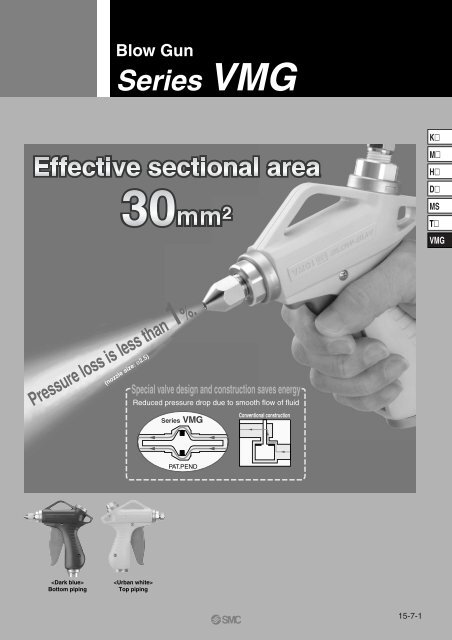
3Before ImprovementExample of ImprovementIn the case of air guns, energy saving measures are not considered.S1S2Effective area ratio2.3 : 1Pressure loss: LargeWithout nozzleø3ø3Pressure Loss of Air <strong>Gun</strong> OnlyEffective area(mm 2 )Effective area ratioNozzle size (mm)Number of nozzlesSupply pressureRegulator pressureOutlet pressurePressure lossUpstream side S1: 15Nozzle side S2: 6.4S1 : S2 = 2.3 : 1ø310.700MPa0.300MPa0.260MPa0.040MPaKMHDMST<strong>VMG</strong>After ImprovementChange to fittings, tubing and <strong>Blow</strong> <strong>Gun</strong> with large effective areas.S1S2FilterregulatorS couplerCoiltubeEffective area ratio10.7 : 1Pressure loss: SmallNozzleø2ø2Effect of Energy Saving ImprovementAir consumptionMin. 90%ReductionPressure Loss of <strong>Blow</strong> <strong>Gun</strong> OnlyEffective area(mm 2 )Effective area ratioNozzle size (mm)Number of nozzlesSupply pressureRegulator pressureOutlet pressurePressure lossUpstream side S1: 30Nozzle side S2: 2.8S1 : S2 = 10.7 : 1ø210.700MPa0.300MPa0.297MPa0.003MPaBeforeAfterNozzle: Series KN⋅⋅⋅⋅⋅⋅⋅⋅⋅⋅⋅⋅⋅⋅⋅⋅⋅⋅⋅⋅⋅⋅⋅⋅⋅P.15-7-7S coupler: Series KK⋅⋅⋅⋅⋅⋅⋅⋅⋅⋅⋅⋅⋅⋅⋅⋅⋅⋅⋅⋅⋅P.15-7-8S coupler: Series KKH⋅⋅⋅⋅⋅⋅⋅⋅⋅⋅⋅⋅⋅⋅⋅⋅⋅⋅⋅P.15-7-8Related Products:S coupler: Series KKA⋅⋅⋅⋅⋅⋅⋅⋅⋅⋅⋅⋅⋅⋅⋅⋅⋅⋅P.15-7-8Regulator: Series AR ⋅⋅⋅⋅⋅⋅⋅⋅⋅⋅⋅⋅⋅⋅⋅⋅⋅⋅⋅P.15-7-9Filter regulator: Series AW⋅⋅⋅⋅⋅⋅⋅⋅⋅⋅⋅P.15-7-1015-7-3
4<strong>Blow</strong> <strong>Gun</strong>Series <strong>VMG</strong>How to Order<strong>VMG</strong> 11 W 03 01<strong>Blow</strong> gunStandard typeSeries1 Resin body lever typePiping entry1 Bottom2 TopWBUBody colorUrban whiteDark bluePiping connection typeNilNFRcNPTGNozzleNil010203041112132122232431323334Note 1)CopperextensionnozzleTypeMale thread nozzleHigh efficiency nozzleLow noise nozzlewith male threadConnection sizePiping connection system02Screw-in type0311 With S coupler plugLength300mmLength600mmNozzle modelWithout nozzleKN-R02-100KN-R02-150KN-R02-200KN-R02-250KNH-R02-100KNH-R02-150KNH-R02-200KNS-R02-075-4KNS-R02-090-8KNS-R02-100-4KNS-R02-110-8KNL3-06-150KNL3-06-200KNL6-06-150KNL6-06-200Port sizePlug part no.Size and part no.1/43/8KK4P-02MSNozzle sizeø1ø1.5ø2ø2.5ø1ø1.5ø2ø0.75 x 4ø0.9 x 8ø1 x 4ø1.1 x 8ø1.5ø2ø1.5ø2Note 1) One piece of H06-02 self-align fitting is attached.When a copper extension nozzle is ordered separately, a self-align fitting will alsobe required for connection. Order one with the above part number in addition tothe nozzle.Note1)Note 1) In case of a type with an S coupler plug, specify no symbol (Rc) for the piping connection type.The size is Rc 1/4.SpecificationsFluidOperating pressure rangeProof pressureAmbient and fluid temperatureEffective areaPort sizePiping entryNozzle port sizeWeightOperational force (when the valve is fully open)Air0 to 1.0MPa1.5MPa5 to 60 C (With no condensation)30mm 2 (without nozzle)Rc, NPT, G, 1/4, 3/8BottomTopRc 1/4180g7N15-7-4
<strong>Blow</strong> <strong>Gun</strong> Series <strong>VMG</strong>5Construction!2ot!4!1 !0!9@1 @0!5qw!8e!3rui!8!7yComponent PartsNo.qwertyuio!0!1!2!3!4!5!6!7!8!9@0@1DescriptionBody LBody RMain valveValve guideNozzle holderPortElbowCoverRingArm LArm RSpringMain valve sealGuide coverLeverTubeO-ringO-ringParallel pinRound head Phillips screwHexagon nutMaterialPBTPBTPBTAluminium alloyAluminium alloyAluminium alloyPBTStainless steelStainless steelStainless steelStainless steelStainless steelHNBRStainless steelPBTPBTNBRNBRStainless steelStainless steelStainless steelNoteChromateAnodizedAnodized∗Only for <strong>VMG</strong>11KMHDMST<strong>VMG</strong>Flow CharacteristicsNote) Values when the main valve is fully open.Male thread nozzleFlow rate [l/min (ANR)]600500400300200100KN-R02-250KN-R02-200KN-R02-150KN-R02-100High efficiency nozzleFlow rate [l/min (ANR)]40035030025020015010050KNH-R02-200KNH-R02-150KNH-R02-10000.1 0.2 0.3 0.4 0.5 0.6 0.7 0.8 0.9 100.1 0.2 0.3 0.4 0.5 0.6 0.7 0.8 0.9 1Supply pressure [MPa]Supply pressure [MPa]Low noise nozzle with male threadFlow rate [l/min (ANR)]900800KNS-R02-110-8700600500KNS-R02-090-8400300200KNS-R02-100-4KNS-R02-075-410000.1 0.2 0.3 0.4 0.5 0.6 0.7 0.8 0.9 1Supply pressure [MPa]Copper extension nozzleFlow rate [l/min( ANR)]400350KNL3-06-200KNL6-06-200300250200KNL3-06-150KNL6-06-1501501005000.1 0.2 0.3 0.4 0.5 0.6 0.7 0.8 0.9 1Supply pressure [MPa]15-7-5
Series <strong>VMG</strong>6Dimensions<strong>VMG</strong>11/Piping entry: BottomRc 1/4Nozzle1562330AWidth across flats22102117.5Note 1)34.2Rc, NPT, G 1/4, 3/8S coupler plug mounting<strong>VMG</strong>12/Piping entry: TopWidth across flats 22Rc, NPT, G 1/4, 3/834.2Note 1)Rc 1/4Nozzle147S coupler plug mounting172.52330A102117.5TypeMale thread nozzleHigh efficiency nozzleNozzle modelKN-R02-100KN-R02-150KN-R02-200KN-R02-250KNH-R02-100KNH-R02-150KNH-R02-200Nozzle sizeø1ø1.5ø2ø2.5ø1ø1.5ø2mmmmA Note 1)23.42322.522.1444444TypeLow noise nozzlewith male threadCopper extension nozzle(with self align fitting H06-02)Nozzle modelKNS-R02-075-4KNS-R02-090-8KNS-R02-100-4KNS-R02-110-8KNL3-06-150KNL3-06-200KNL6-06-150KNL6-06-200Nozzle sizeø0.75 x 4ø0.9 x 8ø1 x 4ø1.1 x 8ø1.5ø2ø1.5ø2A Note 1)12121212305.3305.3605.3605.3Note 1) Reference dimensions after installation15-7-6
<strong>Blow</strong> <strong>Gun</strong> Series <strong>VMG</strong>7Dimensions: Nozzle/Series KNMale thread nozzle: KNModelKN-R02-100KN-R02-150KN-R02-200KN-R02-250Nozzle sizeDø1ø1.5ø2ø2.5ConnectionthreadR 1/4R 1/4R 1/4R 1/4Width across flatsH114141414L131.43130.530.1A25.42524.524.1Connection threadDH1AL1(mm)KMHHigh efficiency nozzle: KNHModelKNH-R02-100KNH-R02-150KNH-R02-200Nozzle sizeDø1ø1.5ø2ConnectionthreadR 1/4R 1/4R 1/4Width across flatsH1141414L1525252A464646Connection threadH1AL1(mm)øDDMST<strong>VMG</strong>Low noise nozzle with male thread: KNSModelNozzle sizeDKNS-R02-075-4 ø0.75 x 4KNS-R02-090-8 ø0.9 x 8KNS-R02-100-4 ø1 x 4KNS-R02-110-8 ø1.1 x 8Connection Width across flatsthread H1L1 AR 1/4 142014R 1/4 142014R 1/4 142014R 1/4 142014øDH12AL1(mm)ConnectionthreadCopper extension nozzle: KNL(mm)ModelKNL3-06-150KNL3-06-200KNL6-06-150KNL6-06-200Nozzle sizeDø1.5ø2ø1.5ø2Outside diameterø6ø6ø6ø6L1300300600600Note) When a copper extension nozzle is ordered separately, a self-align fitting will also berequired for connection with the blow gun. Order one with the following part number inaddition to the nozzle.øDL1OutsidediameterSelf-align fittings (For copper extension nozzle connection)Half unionH06-0215-7-7
8Product Profile:Related Products: S CouplersSeries KK/KKH/KKASeries KKEffective area: 3.8 to 82 mm 2Weight: 6.1 to 87.7 g(Series KK2)(Series KK2)General purpose type(Series KK6)(Series KK6)With sleeve lock mechanism (Except KK2)Series KKHWith shock absorption coverUse of rubber sleeve cover and shockresistant cover ring enables Series KKHto absorb impact energy when dropped.Effective area is equivalent to that of Series KK.KK2KK3·4·6For details on this product, refer to page 15-2-75.For details on this product, refer to page 15-2-86.Series KKA Stainless steel typeBody material: Stainless steel 304Seal material: FKMNon-greased specificationFor details on this product, refer to page 15-2-89.15-7-8
9Related Products: RegulatorSeries AR30 to 60How to OrderAR30JIS SymbolStandard SpecificationsModelPort sizeFluidProof pressureMaximum operating pressureRegulating pressure rangeGauge port size Note 1)Relief pressureAmbient and fluid temperatureConstructionWeight (kg)NilNFAR 30RegulatorBody size3040 1 250 3 460 1Thread typeMetric thread (M5)RcNPTGFPort size02 1 4030406 3 410 103BEAccessory/Option Specifications CombinationsAccessory/Option specificationsAccessoryOptionspecifications3 8Note 1)3 81 2With bracket (with set nut)Square embedded type pressure gaugeCombinationSymbolRound pressure gaugePanel mount (with set nut)0.02 to 0.2MPa settingNon-relieving typeFlow direction: Right LeftDisplay units for product nameplate and pressure gauge: PSI, F.BEGP1NRZOptionSymbolNilBEG Note 2)P1NOption specificationsSymbol1 Note 1)NRZ Note 2)AR301 4 , 3 8AR401 4 , 3 8 , 1 2AR40-063 4AR503 4 , 1AR601Air1.5MPa1.0MPa0.05 to 0.85MPa1 8 1 41 4 1 4 1 4Set pressure + 0.05MPa (at relief flow rate of 0.1l/min(ANR))5 to 60 C (With no condensation)Relieving type1.220.290.440.471.17Note 1) The type with square embedded pressure gauge does not have connection threads.Contents0.02 to 0.2MPa settingNon-relievingFlow direction: Right LeftDisplay units for product name plate and pressure gauge: PSI, F.ContentsWith bracketWith square embedded type pressure gauge (with limit indicator)Round pressure gauge (with limit indicator)Panel mount (with set nut)Applicable modelsAR30 to 60AR30 to 60AR30 to 60AR30 to 60When more than one specification is required, indicate in ascending alphanumericorder.Note 1) The only difference from the standard specifications is the adjustingspring for the regulator. It does not restrict the setting of 0.2MPa or more.Note 2) For M5 and NPT thread types. Under the New Measurement Law, theproduct is only sold outside Japan. (The SI unit is used inside Japan.)Applicable modelsAR30 to 60AR30 to 60AR30 to 60AR30 to 40Note 1) Bracket assembly is not mounted at the time of shipment, but rather packagetogether with the regulator.Note 2) Mounting threads pressure gauge: AR301/8; AR40 to 601/4.Pressure gauge is not mounted at the time of shipment, but rather packagedtogether with the regulator.: Combination available : Combination not available: Varies depending on the model : Available only with NPT threadAccessory Option specifications Applicable regulatorsB E G P 1 N R Z AR30 to 60KMHDMST<strong>VMG</strong>Option/Part No.OptionBracket assemblySet nutNote 2)Pressuregauge1MPa0.2MPaApplicable modelNote 1)RoundSquare Note 3)embedded typeRoundSquare Note 3)embedded typeAR30AR30P-270ASAR30P-260SG36-10-01GC3-10ASG36-2-01GC3-2ASAR40AR40-06AR50AR40P-270ASAR40P-260SG46-10-02GC3-10ASG46-2-02GC3-2ASAR40P-270ASAR40P-260SG46-10-02GC3-10ASG46-2-02GC3-2ASAR50P-270ASG46-10-02GC3-10ASG46-2-02GC3-2ASAR60Note 4) Note 4)AR50P-270ASG46-10-02GC3-10ASG46-2-02GC3-2ASNote 1) Assembly includes a bracket and set nuts.Note 2) in part numbers for a round pressure gauge indicates a type of connection threads. Noindication is necess-ary for R; however, indicate and N for NPT. Please contact SMC for regardingthe connection thread NPT and pressure gauge supply for PSI unit specifications.Note 3) Includes one O-ring and 2 mounting screws.Note 4) Assembly includes a bracket and 2 mounting screws.Note 5) Please contact SMC regarding the set nuts for AR50 and AR60.Note 5)Note 5)15-7-9
10Related Products: Filter RegulatorSeries AW30/40Integration of afilter and regulatorallows simplewiring.AW40Direct operated type,Relieving typeOption specifications AccessoryAWFilterregulatorBody size30401 230 F 03 BE 1N3 83 4Thread typeNilMetric thread (M5)RcNote 1)NNPTF Note 2) GNote 1) Drain guide is NPT1/4(applicable to AW30 and 40),and the exhaust port for autodrain comes with ø3/8" Onetouchfitting (applicable toAW30 and 40).Note 2) Drain guide is G1/4(applicable to AW30 and 40).How to OrderOption specificationsSymbol1 Note 1)268JNRWZNote 2)Note 3)AccessorySymbolNilB Note 1)CDEContents0.02 to 0.2MPa settingMetal bowlNylon bowlMetal bowl with level gaugeDrain guide 1/4Non-relievingFlow direction: Right LeftDrain cock with barb fitting: ø6 x ø4 nylon tubeDisplay units for product name plate, caution plate for bowl, and pressure gauge: PSI, FContents—Applicable modelsAW30/40AW30/40AW30/40AW30/40AW30/40AW30/40AW30/40AW30/40AW30/40When more than one specification is required, indicate in ascending alphabeticalorder.Note 1) The only difference from the standard specifications is the adjustingspring for the regulator. It does not restrict the setting of 0.2MPa or more.Note 2) Without valve function.Note 3) For M5 and NPT thread types. Under the New Measurement Law, thistype is only sold outside Japan. (The SI unit is used inside Japan.)Applicable models—AW30/40AW30/40AW30/40AW30/40AW30/40AW30/40With bracketPort sizeFloat type auto-drain (N.C)02 1 Float type auto-drain (N.O)JIS Symbol4With square embedded type pressure gauge (with limit indicator)03 3 8Note 2) G With round pressure gauge (with limit indicator)04 1 2P Panel mount (with set nut)Proof pressure1.5MPaSet nutAR30P-260S AR40P-260S AR40P-260SMaximum operating pressure1.0MPaRoundRegulating pressure rangeG36-10-01 G46-10-02 G46-10-020.05 to 0.85MPa1.0MPaNote 2)Square Note 3)Pressure gauge port size Note 1) 1 8 1 41 PressureGC3-10AS GC3-10AS GC3-10AS4 embedded type06Note 1) Bracket assembly is not mounted at the time of shipment, but rather packagedtogether with the filter regulator for shipment.Note 2) Mounting thread for pressure gauge: AW30—1/8; AR40 to 60—1/4.Pressure gauge is not mounted at the time of shipment, but rather packagedtogether with the regulator for shipment.Accessory/: Combination available : Combination not availableOption Specifications Combinations: Varies depending on the model : Available only with NPT threadAccessory/CombinationAccessoryOption specificationsApplicable filter regulatorSymbolOption specificationsB C D E G P 1 2 6 8 C J N R W Z AW30/40With bracket (with set nut)BFloat type auto drain (N.C.)CFloat type auto drain (N.O.)DSquare embedded type pressure gaugeERound pressure gaugeGPanel mount (with set nut)P0.02 to 0.2MPa setting–1Metal bowl–2Nylon bowl–6Metal bowl with level gauge–8With bowl guard–CDrain guide 1 4 –JNon-relieving type–NFlow direction: Right Left–RDrain cock with barb fitting: ø6 x ø4 nylon tubing–WDisplay units for product name plate, caution plate for bowl, and pressure gauge: PSI, F –ZStandard SpecificationsAccessory Part No.ModelAW30 AW40 AW40-06Applicable modelPort size1 4 , 3 8 1 4 , 3 8 , 1 23 4 AccessoryAW30AW40 AW40-06FluidAirNote 1)Bracket assemblyAR30P-270AS AR40P-270AS AR40P-270ASRelief pressureSet pressure + 0.05MPa (at relief flow rate of 0.1l/min(ANR)) gaugeRoundG36-2-01 G46-2-02 G46-2-020.2MPaAmbient and fluid temperature 5 to 60 Square Note 3)C (With no condensation)embedded type GC3-2AS GC3-2AS GC3-2ASNominal filtration rating5µmNote 4)Float typeN.O.AD38AD48AD48Drain capacity (cm 3 )25 45 45 auto-drainN.C.AD37AD47AD47Bowl materialPolycarbonateNote 1) Assembly includes a bracket and set nuts.ConstructionRelieving typeNote 2) in part numbers of the round pressure gauge indicates a type of connectionWeight (kg)0.40 0.72 0.75thread. No indication is necessary for R; however, indicate N for NPT. Pleasecontact SMC regarding the connection thread NPT and supply of the pressureOption Bowl guard gauge for PSI unit specifications.Note 1) The type with square embedded pressure gauge does Note 3) Includes one O-ring and 2 mounting screws.Note 4) Minimum operating pressure: N.O. type—0.1MPa; N.C. type—0.1MPa AD17, AD27not have connection threads.and 0.15MPa for AD37, AD47. Please contact SMC regarding the specifications forPSI unit and F.15-7-10
Series <strong>VMG</strong>Specific Product Precautions 1Be sure to read before handling.11WarningSelection1. Confirm the specifications.The products in this catalog are designed to be used incompressed air systems only. If the products are used in anenvironment where pressure or temperature is out of the specifiedrange, damage and/or malfunction may result. Do not use undersuch conditions.Caution1. Do not apply the blow gun to flammable,explosive or toxic substances such as gas,fuel gas or refrigerant. Such substancesmay exude from inside the blow gun.CautionPiping1. Confirm the model, type and size beforeinstallation.Also make sure that there is no scratches, gouges or cracks onthe product.2. Before pipingBefore piping, it should be thoroughly blown out with air (flushing)or washed to remove chips, cutting oil and other debris frominside the pipe.3. Wrapping of pipe tapeWhen screwing together pipes and fittings, etc., be certain thatchips from the pipe threads and sealing material do not get insidethe piping. Also, when the pipe tape is used, leave 1.5 to 2 threadridges exposed at the end of the threads.Wrapping directionKMHDMST<strong>VMG</strong>Expose approx. 2 threadsWarningMounting1. Install a stop valve on the supply pressureside of the blow gun to enable emergencyshut off in case of unexpected leakage ordamage.2. When installing a nozzle on the blow gun,wrap seal tape around the threads of thenozzle.3. When installing the nozzle, secure thenozzle holder of the blow gun by applying aspanner of 22 mm width across flats to thetwo chamfered surfaces of the holderwithout applying force to the body. Thentighten the nozzle with force within thefollowing torque ranges. As a guideline, it isequivalent to 2 to 3 additional turns with atool after manual tightening.Nozzle tightening torque rangeSpanner12 to 14NmNozzle holderInsufficient tightening may cause loosening of the nozzle.4. When installing the nozzle, secure the nozzleholder of the blow gun by applying aspanner of 22 mm width across flats to thetwo chamfered surfaces of the holderwithout applying force to the body. Thentighten the nozzle with torque specified inthe table below. As a guideline, it isequivalent to 2 to 3 additional turns using atool after manual tightening.Be careful that tightening with torque beyond the ranges in thetable below may cause damage to the body.SpannerPortMale threadR 1/4R 3/8Pipe tapeTightening torque N⋅m12 to 1422 to 245. Allow extra length when connecting the tubeto accommodate changes in tube length dueto pressure.6. Make sure that no twisting, turning or tensileforce or moment load is applied to the portor tube. It may cause the fittings to fractureor the tubing to crush, explode or comeloose.7. Do not abrade, entangle or scratch thetubing. It may cause the tubing to crush,explode or come loose.15-7-11
Series <strong>VMG</strong>Specific Product Precautions 2Be sure to read before handling.12WarningWarning1. Use clean air.Do not use compressed air which includes chemicals, syntheticoils containing organic solvents, salt or corrosive gases, etc., as itcan cause damage or malfunction.CautionWarningLubrication1. Do not lubricate the product.It may contaminate or damage the target object.Air Supply1. Install air filters.Install air filters at the upstream side of blow gun. The filtration degreeshould be 5µm or finer.2. Install an after-cooler, air dryer or waterseparator, etc.Air excessive drainage may cause malfunction of blow gun andcontaminate or damage the target object. To prevent this, installan after-cooler, air dryer or water separator, etc.Operating Environment1. Do not use in an atmosphere of corrosivegases, chemicals, sea water, water or watervapor or in an environment where suchsubstances may adhere.2. Provide shading in an environment wherethe product is exposed to the sunlight.3. Do not use in an environment where a heatsource is at a close distance.4. Do not use in an environment where staticelectricity is a problem. It may causemalfunction or failure of the system. Pleaseconsult with SMC for use in such anenvironment.5. Do not use in an environment where spattersare generated. There is danger of firescaused by spattering. Please contact SMCfor use in such an environment.6. Do not use in an environment where theproduct is exposed to cutting oil, lubricantoil or coolant oil. Please contact SMC for usein an environment where the product isexposed to such liquid as cutting oil,lubricant oil or coolant oil.Caution1. In periodical inspections, check the followingitems and replace the parts if necessary.a) Scratches, gouges, abrasion, corrosionb) Air leakagec) Twisting, crushing and turning of connected tubesd) Hardening, deterioration and softening of connected tubese) Loosening of the nozzle2. When removing the product, first stop thepressure supply, exhaust compressed air inthe piping and confirm the condition ofatmospheric release.3. Do not disassemble or remodel the body ofthe product.WarningMaintenanceHandling1. To prevent lurching of the nozzle due to airpressure, confirm that the nozzle is notloosened or rattling by pulling it by handbefore operation.2. Be sure to wear safety goggles to protectyourself from splashed substances.3. Do not direct the tip of the nozzle at the faceor other parts of a human body. It may causedanger to personnel.4. Do not use the product to clean or removetoxic substances or chemicals.5. Do not drop, step on or hit the product. Itmay cause damage to the product.6. Do not use the product to disturb publicorder or public hygiene.7. This product is not a toy.15-7-12