EJX110A Standard Differential Pressure Transmitter - Illawarra ...
EJX110A Standard Differential Pressure Transmitter - Illawarra ...
EJX110A Standard Differential Pressure Transmitter - Illawarra ...

Create successful ePaper yourself
Turn your PDF publications into a flip-book with our unique Google optimized e-Paper software.
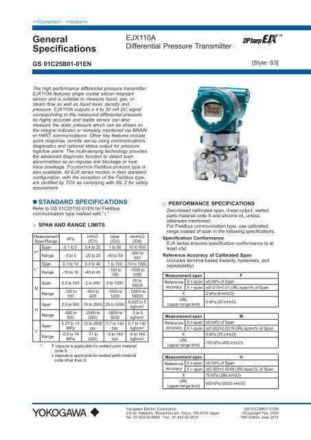
GeneralSpecifications<strong>EJX110A</strong><strong>Differential</strong> <strong>Pressure</strong> <strong>Transmitter</strong>GS 01C25B01-01EN[Style: S3]The high performance differential pressure transmitter<strong>EJX110A</strong> features single crystal silicon resonantsensor and is suitable to measure liquid, gas, orsteam flow as well as liquid level, density andpressure. <strong>EJX110A</strong> outputs a 4 to 20 mA DC signalcorresponding to the measured differential pressure.Its highly accurate and stable sensor can alsomeasure the static pressure which can be shown onthe integral indicator or remotely monitored via BRAINor HART communications. Other key features includequick response, remote set-up using communications,diagnostics and optional status output for pressurehigh/low alarm. The multi-sensing technology providesthe advanced diagnostic function to detect suchabnormalities as an impulse line blockage or heattrace breakage. FOUNDATION Fieldbus protocol type isalso available. All EJX series models in their standardconfiguration, with the exception of the Fieldbus type,are certified by TÜV as complying with SIL 2 for safetyrequirement.• STANDARD SPECIFICATIONSRefer to GS 01C25T02-01EN for Fieldbuscommunication type marked with “◊.”□ SPAN AND RANGE LIMITSMeasurementSpan/RangeF*L*MHVkPainH2O(/D1)mbar(/D3)mmH2O(/D4)Span 0.1 to 5 0.4 to 20 1 to 50 10 to 500Range -5 to 5 -20 to 20 -50 to 50-500 to500Span 0.1 to 10 0.4 to 40 1 to 100 10 to 1000Range -10 to 10 -40 to 40-100 to100Span 0.5 to 100 2 to 400 5 to 1000Range-100 to100-400 to400-1000 to1000Span 2.5 to 500 10 to 2000 25 to 5000RangeSpanRange-500 to5000.07 to 14MPa-0.5 to 14MPa-2000 to200010 to 2000psi-71 to2000-5000 to50000.7 to 140bar-5 to 140bar*: F capsule is applicable for wetted parts materialcode S.L capsule is applicable for wetted parts materialcode other than S.-1000 to100050 to10000-10000 to100000.025 to 5kgf/cm 2-5 to 5kgf/cm 20.7 to 140kgf/cm 2-5 to 140kgf/cm 2□ PERFORMANCE SPECIFICATIONSZero-based calibrated span, linear output, wettedparts material code S and silicone oil, unlessotherwise mentioned.For Fieldbus communication type, use calibratedrange instead of span in the following specifications.Specification ConformanceEJX series ensures specification conformance to atleast ±3σ.Reference Accuracy of Calibrated Span(includes terminal-based linearity, hysteresis, andrepeatability)Measurement spanFReference X ≤ span ±0.04% of Spanaccuracy X > span ±(0.015+0.01 URL/span)% of SpanX 2 kPa (8 inH2O)URL(upper range limit)5 kPa (20 inH2O)Measurement spanMReference X ≤ span ±0.04% of Spanaccuracy X > span ±(0.002+0.0019 URL/span)% of SpanX 5 kPa (20 inH2O)URL(upper range limit)100 kPa (400 inH2O)Measurement spanHReference X ≤ span ±0.04% of Spanaccuracy X > span ±(0.005+0.0049 URL/span)% of SpanX 70 kPa (280 inH2O)URL(upper range limit)500 kPa (2000 inH2O)Yokogawa Electric Corporation2-9-32, Nakacho, Musashino-shi, Tokyo, 180-8750 JapanTel.: 81-422-52-5690 Fax.: 81-422-52-2018GS 01C25B01-01EN©Copyright Feb. 200416th Edition June 2012
2Measurement spanVReference X ≤ span ±0.04% of Spanaccuracy X > span ±(0.005+0.00125 URL/span)% of SpanX 500 kPa (2000 inH2O)URL(upper range limit)14 MPa (2000 psi)Square Root Output AccuracyThe square root accuracy is a percent of flow span.OutputAccuracy50% or Greater Same as reference accuracy50% to Dropout pointReference accuracy × 50Square root output (%)Ambient Temperature Effects per 28°C (50°F)ChangeCapsuleFMH, VEffect±(0.055% Span + 0.18% URL)±(0.04% Span + 0.009% URL)±(0.04% Span + 0.0125% URL)• Total Probable Error (M capsule)±0.12% of Span @1:1 to 5:1 RangedownTotal probable error, known as a measure of the totalperformance of the transmitters under the condition offixed line presurre.Total Probable Error = ± E 12 + E 22 + E 32E1: Reference Accuracy of Calibrated SpanE2: Ambient Temperature Effects per 28°C changeE3: Static Span Effects per 6.9 MPa change• Total Accuracy (M capsule)±0.12% of Span @1:1 Rangedown±0.25% of Span @ 5:1 RangedownTotal accuracy is a comprehensive measure oftransmitter total performance, covering all majorfactors in actual installation, that cause errors inmeasurement.As a standard measure, YOKOGAWA uses this toevaluate transmitter performance.Total Accuracy = ± E 12 + E 22 + (E 3 + E 4 ) 2 + E 52E1: Reference Accuracy of Calibrated SpanE2: Ambient Temperature Effects per 28°C changeE3: Static Span Effects per 6.9 MPa changeE4: Static Zero Effects per 6.9 MPa changeE5: Overpressure Effects upto overpressure 25MPaNot only a day-to-day changes in temperature canaffect the measurement and lead to unnoticed errors;fluctuaion of line pressure, incorrect operation ofthree/five valve manifold leading to over-pressureevents, and other phenomena can have the similarresult. Total Accuracy factors in such changes anderrors and provides much comprehensive andpractical determination of how a transmitter willperform under actual plant operation.Static <strong>Pressure</strong> Effects per 6.9 MPa (1000 psi)ChangeSpan EffectsF, M, H and V capsules±0.075% of spanEffect on ZeroCapsuleEffectFMH, V±0.1% URL±0.02% URL±0.028% URLOverpressure EffectsOverpressure condition: up to maximum workingpressureM, H and V capsules±0.03% of URLStability (All normal operating condition, includingoverpressure effects)M, H and V capsules±0.1% of URL per 10 yearsPower Supply Effects(Output signal code D and E)±0.005 % per Volt (from 21.6 to 32 V DC, 350Ω)Vibration EffectsAmplifier housing code 1 and 3:Less than 0.1% of URL when tested per therequirements of IEC60770-1 field or pipeline withhigh vibration level (10-60 Hz, 0.21 mm peak to peakdisplacement/60-2000 Hz 3 g)Amplifier housing code 2:Less than ±0.1% of URL when tested per therequirements of IEC60770-1 field with generalapplication or pipeline with low vibration level (10-60Hz 0.15mm peak to peak displacement /60-500 Hz2g)Mounting Position EffectsRotation in diaphragm plane has no effect. Tiltingup to 90 degree will cause zero shift up to 0.4 kPa(1.6 inH2O) which can be corrected by the zeroadjustment.Response Time (<strong>Differential</strong> pressure) “◊”90 ms for Wetted Parts material code S except forMeasuring span code F. 150 ms for Wetted PartsMaterial Code H, M, T, A, B and D or Measuring spancode F.When amplifier damping is set to zero and includingdead time of 45 ms (nominal)Static <strong>Pressure</strong> Signal Range and Accuracy(For monitoring via communication or onindicator. Includes terminal-based linearity,hysteresis, and repeatability)RangeUpper Range Value and Lower Range Value of thestatice pressure can be set in the range between 0and Maximum Working <strong>Pressure</strong>(MWP). The upperrange value must be greater than the lower rangevalue. Minimum setting span is 0.5 MPa(73 psi).Measuring either the pressure of high pressure sideor low pressure side is user-selectable.All Rights Reserved. Copyright © 2004, Yokogawa Electric CorporationGS 01C25B01-01ENJune 20, 2012-00
AccuracyAbsolute <strong>Pressure</strong>1 MPa or higher: ±0.2% of spanLess than 1 MPa: ±0.2%×(1 MPa/span) of spanGauge <strong>Pressure</strong> ReferenceGauge pressure reference is 1013 hPa (1 atm)Note: Gauge pressure variable is based on the abovefixed reference and thus subject to be affected bythe change of atomospheric pressure.□ FUNCTIONAL SPECIFICATIONSOutput “◊”Two wire 4 to 20 mA DC output with digitalcommunications, linear or square root programmable.BRAIN or HART FSK protocol are superimposed onthe 4 to 20 mA signal.Output range: 3.6 mA to 21.6 mAOutput limits conforming to NAMUR NE43 can bepre-set by option code C2 or C3.Failure Alarm (Output signal code D and E)Analog output status at CPU failure and hardwareerror;Up-scale: 110%, 21.6 mA DC or more (standard)Down-scale: −5%, 3.2 mA DC or lessAnalog output status at process abnormality (Optioncode /DG6);The result of process abnormality detected by theadvanced diagnostic function can be reflected toan analog alert status. The following three settingmodes are available.<strong>Standard</strong>OptionCode/C1/C2/C3ModeBurnout Fall back Off110%,21.6mA or more-2.5%,3.6mA or less-1.25%,3.8mA or less103.1%,20.5mA or moreHolds to aspecified valuewithin theoutput rangefrom 3.6mA to21.6mANormal output(No analogoutput alarm)Damping Time Constant (1st order)Amplifier damping time constant is adjustable from0.00 to 100.00 s by software and added to responsetime.Note: For BRAIN protocol type, when amplifier softwaredamping is set to less than 0.5 s, communicationmay occasionally be unavailble during theoperation, especially while output changesdynamically. The default setting of dampingensures stable communication.Update Period “◊”<strong>Differential</strong> pressure: 45 msStatic pressure: 360 msZero Adjustment LimitsZero can be fully elevated or suppressed, within thelower and upper range limits of the capsule.External Zero AdjustmentExternal zero is continuously adjustable with0.01% incremental resolution of span. Re-rangecan be done locally using the digital indicator withrangesetting switch.Integral Indicator (LCD display, optional) “◊”5-digit numerical display, 6-digit unit display and bargraph.The indicator is configurable to display one or up tofour of the following variables periodically.;Measured differential pressure, differential pressurein %, scaled differential pressure, measured staticpressure. See also “Factory Setting.”Burst <strong>Pressure</strong> Limits69 MPa (10,000 psi) for wetted parts material S,except for Measurement span F.47 MPa (6,800 psi) for wetted parts material otherthan S or Measurement span F.Self DiagnosticsCPU failure, hardware failure, configuration error,and over-range error for differential pressure, staticpressure and capsule temperature.User-configurable process high/low alarm fordifferential pressure and static pressure is alsoavailable, and its status can be output when optionalstatus output is specified.Advanced Diagnostics (optional) “◊”Applicable for Output signal code E and F.• Impulse line blockage detectionThe impulse line condition can be calculated anddetected by extracting the fluctuation componentfrom the differential pressure and static pressuresignals. The <strong>EJX110A</strong> detects the impulse lineabnormality particularly which side of impulse line isplugged.• Heat trace monitoringThe change of the flange temperature calculated byusing the two temperature sensors built in the EJXenables to detect the heat trace breakage or theabnormal temperature due to the failure.Signal Characterizer (Output signal code D and E)User-configurable 10-segment signal characterizerfor 4 to 20 mA output.Status Output (optional, output signal code Dand E)One transistor contact output (sink type) to outputthe status of user configurable high/low alarm fordifferential pressure/static pressure.Contact rating: 10.5 to 30 V DC, 120 mA DC max.Refer to ‘Terminal Configuration’ and ‘Wiring Examplefor Analog Output and Status Output.’SIL CertificationEJX series transmitters except Fieldbuscommunication type are certified by TÜV incompliance with the following standards;IEC 61508: 2000; Part1 to Part 7Functional Safety of Electrical/electronic/programmable electronic related systems; SIL 2capability for single transmitter use, SIL 3 capabilityfor dual transmitter use.3All Rights Reserved. Copyright © 2004, Yokogawa Electric CorporationGS 01C25B01-01ENJune 20, 2012-00
□ NORMAL OPERATING CONDITION(Optional features or approval codes mayaffect limits.)Ambient Temperature Limits−40 to 85°C (−40 to 185°F)−30 to 80°C (−22 to 176°F) with LCD displayProcess Temperature Limits−40 to 120°C (−40 to 248°F)Ambient Humidity Limits0 to 100% RHWorking <strong>Pressure</strong> Limits (Silicone oil)Maximum <strong>Pressure</strong> Limits (MWP)CapsuleMWPF, L 16 MPa (2300 psi)Wetted Parts Material: S 25 MPa (3600 psi)M, H, V Wetted Parts Material:16 MPa (2300 psi)H, T, M, A, D, BMinimum <strong>Pressure</strong> LimitSee graph below100(14.5)WorkingpressurekPa abs(psi abs)10(1.4)2.7(0.38)1(0.14)-40(-40)Applicable range0(32)40(104)80(176)Process temperature °C (°F)Atmosphericpressure120(248)F01E.aiFigure 1. Working <strong>Pressure</strong> and Process TemperatureSupply & Load Requirements(Output signal code D and E. Optional featuresor approval codes may affect electricalrequirements.)With 24 V DC supply, up to a 550Ω load can beused. See graph below.R (Ω)600Externalloadresistance250R=E-10.50.0244DigitalCommunicationrangeBRAIN and HART410.5 16.6 25.2 42Power supply voltage E (V DC)Figure 2. Relationship Between Power SupplyVoltage and External Load ResistanceF02E.aiSupply Voltage “◊”10.5 to 42 V DC for general use and flameproof type.10.5 to 32 V DC for lightning protector(option code /A.)10.5 to 30 V DC for intrinsically safe, type n, ornonincendive.Minimum voltage limited at 16.6 V DC for digitalcommunications, BRAIN and HARTLoad (Output signal code D and E)0 to 1290Ω for operation250 to 600Ω for digital communicationCommunication Requirements “◊”(Approval codes may affect electrical requirements.)BRAINCommunication DistanceUp to 2 km (1.25 miles) when using CEVpolyethylene-insulated PVC-sheathed cables.Communication distance varies depending on type ofcable used.Load Capacitance0.22 µF or lessLoad Inductance3.3 mH or lessInput Impedance of communicating device10 kΩ or more at 2.4 kHz.EMC Conformity <strong>Standard</strong>s ,EN61326-1 Class A, Table2 (For use in industriallocations)EN61326-2-3European <strong>Pressure</strong> Equipment Directive 97/23/ECSound Engineering Practice (for all capsules)With option code /PE3 (for M, H and V capsules andwetted parts material code S.)Category III, Module H, Type of Equipment: <strong>Pressure</strong>Accessory-Vessel, Type of Fluid: Liquid and Gas,Group of Fluid: 1 and 2All Rights Reserved. Copyright © 2004, Yokogawa Electric CorporationGS 01C25B01-01ENJune 20, 2012-00
5□ PHYSICAL SPECIFICATIONSWetted Parts MaterialsDiaphragm, Cover Flange, Process Connector,Capsule Gasket, and Vent/Drain PlugRefer to “MODEL AND SUFFIX CODES.”Process Connector GasketPTFE TeflonFluorinated rubber for option code N2 and N3Non-wetted Parts MaterialsBoltingB7 carbon steel, 316L SST or 660 SSTHousingLow copper cast aluminum alloy with polyurethane,mint-green paint (Munsell 5.6BG 3.3/2.9 or itsequivalent), or ASTM CF-8M Stainless SteelDegrees of ProtectionIP66/IP67, NEMA4XCover O-ringsBuna-N, fluoro-rubber (optional)Name plate and tag316 SSTFill FluidSilicone, fluorinated oil (optional)Weight[Installation code 7, 8 and 9]2.8 kg (6.2 lb) for measurement span code M, Hand V, wetted parts material code S without integralindicator, mounting bracket, and process connector.3.7 kg (8.2 lb) for measurement span code F withoutintegral indicator, mounting bracket, and processconnector.Add 1.5 kg (3.3lb) for Amplifier housing code 2.ConnectionsRefer to “MODEL AND SUFFIX CODES.”Process connection of cover flange: IEC61518< Related Instruments>Power Distributor: Refer to GS 01B04T01-02E orGS 01B04T02-02EBRAIN TERMINAL: Refer to GS 01C00A11-00E< Reference >1. Teflon; Trademark of E.I. DuPont de Nemours &Co.2. Hastelloy; Trademark of Haynes International Inc.3. HART; Trademark of the HART CommunicationFoundation.4. FOUNDATION Fieldbus; Tradmark of FieldbusFoundation.Other company names and product names used inthis material are registered trademarks or trademarksof their respective owners.All Rights Reserved. Copyright © 2004, Yokogawa Electric CorporationGS 01C25B01-01ENJune 20, 2012-00
6• MODEL AND SUFFIX CODESModel Suffix Codes Description<strong>EJX110A</strong> . . . . . . . . . . . . . . . . . . . . . . . . . . . . . . . <strong>Differential</strong> pressure transmitterOutput signal -D . . . . . . . . . . . . . . . . . . . . . . . . . . . . .-E . . . . . . . . . . . . . . . . . . . . . . . . . . . . .-F . . . . . . . . . . . . . . . . . . . . . . . . . . . . .Measurementspan (capsule)F . . . . . . . . . . . . . . . . . . . . . . . . . . . .L . . . . . . . . . . . . . . . . . . . . . . . . . . . .M . . . . . . . . . . . . . . . . . . . . . . . . . . .H. . . . . . . . . . . . . . . . . . . . . . . . . . . .V. . . . . . . . . . . . . . . . . . . . . . . . . . . .4 to 20 mA DC with digital communication (BRAIN protocol)4 to 20 mA DC with digital communication (HART protocol)Digital communication (FOUNDATION Fieldbus protocol, refer toGS 01C25T02-01EN)0.1 to 5 kPa (0.4 to 20 inH 2 O) (For Wetted parts material code S)0.1 to 10 kPa (0.4 to 40 inH 2 O) (For Wetted parts material code M, H, T, A,D and B)0.5 to 100 kPa (2 to 400 inH 2 O)2.5 to 500 kPa (10 to 2000 inH 2 O)0.07 to 14 MPa (10 to 2000 psi)Wetted parts . . . . . . . . . . . . . . . . . . . . . . . . Refer to “Wetted Parts Material” Table.material *2Process connections 0 . . . . . . . . . . . . . . . . . . . . . .1 . . . . . . . . . . . . . . . . . . . . . .2 . . . . . . . . . . . . . . . . . . . . . .3 . . . . . . . . . . . . . . . . . . . . . .4 . . . . . . . . . . . . . . . . . . . . . .► 5 . . . . . . . . . . . . . . . . . . . . . .Bolts and nuts materia J . . . . . . . . . . . . . . . . . . . .G. . . . . . . . . . . . . . . . . . . .C. . . . . . . . . . . . . . . . . . . .Installation-7 . . . . . . . . . . . . . . . .-8 . . . . . . . . . . . . . . . .► -9 . . . . . . . . . . . . . . . .-B . . . . . . . . . . . . . . . .-U . . . . . . . . . . . . . . . .Amplifier housing 1 . . . . . . . . . . . . . . .3 . . . . . . . . . . . . . . .2 . . . . . . . . . . . . . . .Electrical connection0 . . . . . . . . . . . .► 2 . . . . . . . . . . . .4 . . . . . . . . . . . .5 . . . . . . . . . . . .7 . . . . . . . . . . . .9 . . . . . . . . . . . .A. . . . . . . . . . . .C. . . . . . . . . . . .D. . . . . . . . . . . .Integral indicatorD. . . . . . . . .E. . . . . . . . .► N. . . . . . . . .Mounting bracket ► B. . . . . .D. . . . . .J . . . . . .K. . . . . .M . . . . .N. . . . . .Optional Codeswithout process connector (Rc1/4 female on the cover flanges)with Rc1/4 female process connectorwith Rc1/2 female process connectorwith 1/4 NPT female process connectorwith 1/2 NPT female process connectorwithout process connector (1/4 NPT female on the cover flanges)B7 carbon steel316L SST660 SSTVertical piping, left side high pressure, and process connection downsideHorizontal piping and right side high pressureHorizontal piping and left side high pressureBottom Process Connection, left side high pressure *5*6Universal flange *5Cast aluminum alloyCast aluminum alloy with corrosion resistance properties *7ASTM CF-8M stainless steel *3G1/2 female, one electrical connection without blind plugs1/2 NPT female, two electrical connections without blind plugsM20 female, two electrical connections without blind plugsG1/2 female, two electrical connections and a blind plug *41/2 NPT female, two electrical connections and a blind plug *4M20 female, two electrical connections and a blind plug *4G1/2 female, two electrical connections and a SUS316 blind plug1/2 NPT female, two electrical connections and a SUS316 blind plugM20 female, two electrical connections and a SUS316 blind plugDigital indicatorDigital indicator with the range setting switch *1None304 SST 2-inch pipe mounting, flat type (for horizontal piping)304 SST 2-inch pipe mounting, L type (for vertical piping)316 SST 2-inch pipe mounting, flat type (for horizontal piping)316 SST 2-inch pipe mounting, L type (for vertical piping)316 SST 2-inch pipe mounting (for bottom process connection type)None/ Optional specificationThe “►” marks indicate the most typical selection for each specification.*1: Not applicable for output signal code F.*2: Users must consider the characteristics of selected wetted parts material and the influence of process fluids. The use ofinappropriate materials can result in the leakage of corrosive process fluids and cause injury to personnel and/or damageto plant facilities. It is also possible that the diaphragm itself can be damaged and that material from the broken diaphragmand the fill fluid can contaminate the user’s process fluids.Be very careful with highly corrosive process fluids such as hydrochloric acid, sulfuric acid, hydrogen sulfide, sodiumhypochlorite, and high-temperature steam (150°C [302°F] or above). Contact Yokogawa for detailed information of thewetted parts material.*3: Not applicable for electrical connection code 0, 5, 7 and 9.*4: Material of a blind plug is aluminum alloy or 304 SST.*5: Only applicable for Wetted parts material code S.*6: Not applicable for measurement span code F.*7: Not applicable for electrical connection code 0, 5, 7, 9 and A. Content rate of copper in the material is 0.03% or less andcontent rate of iron is 0.15% or less.All Rights Reserved. Copyright © 2004, Yokogawa Electric CorporationGS 01C25B01-01ENJune 20, 2012-00
7Table. Wetted Parts MaterialsWetted partsmaterial codeCover flange and processconnectorCapsule Capsule gasket Drain/Vent plugS # ASTM CF-8M *1 F316L SST or 316L SST Teflon-coated 316L SST 316 SSTHastelloy C-276 *2 (Diaphragm)(Others)H # ASTM CF-8M *1 Hastelloy C-276 *2 PTFE Teflon 316 SSTM # ASTM CF-8M *1 Monel PTFE Teflon 316 SSTT ASTM CF-8M *1 Tantalum PTFE Teflon 316 SSTA # Hastelloy C-276 equivalent *3 Hastelloy C-276 *2 PTFE Teflon Hastelloy C-276 *2D # Hastelloy C-276 equivalent *3 Tantalum PTFE Teflon Hastelloy C-276 *2B # Monel equivalent *4 Monel PTFE Teflon Monel*1: Cast version of 316 SST. Equivalent to SCS14A.*2: Hastelloy C-276 or ASTM N10276.*3: Indicated material is equivalent to ASTM CW-12MW.*4: Indicated material is equivalent to ASTM M35-2.The ‘#’marks indicate the construction materials conform to NACE material recommendations per MR0175/ISO15156.Please refer to the latest standards for details. Selected materials also conform to NACE MR0103.• OPTIONAL SPECIFICATIONS (For Explosion Protected type) “◊”Item Description CodeFactory Mutual FM Explosionproof Approval *1(FM)Applicable <strong>Standard</strong>: FM3600, FM3615, FM3810, ANSI/NEMA 250Explosionproof for Class I, Division 1, Groups B, C and D, Dust-ignitionproof for Class II/III, Division 1,FF1Groups E, F and G, in Hazardous locations, indoors and outdoors (NEMA 4X)“FACTORY SEALED, CONDUIT SEAL NOT REQUIRED.”Temperature class: T6, Amb. Temp.: –40 to 60°C (–40 to 140°F) *3FM Intrinsically safe Approval *1*2Applicable <strong>Standard</strong>: FM3600, FM3610, FM3611, FM3810Intrinsically Safe for Class I, Division 1, Groups A, B, C & D, Class II, Division 1,Groups E, F & G and Class III, Division 1, Class I, Zone 0, in Hazardous Locations, AEx ia IICNonincendive for Class I, Division 2, Groups A, B, C & D, Class II, Division. 2,FS1Groups F & G, Class I, Zone 2, Group IIC, in Hazardous LocationsEnclosure: “NEMA 4X”, Temp. Class: T4, Amb. Temp.: –60 to 60°C (–75 to 140°F) *3Intrinsically Safe Apparatus Parameters[Groups A, B, C, D, E, F and G] Vmax=30 V, Imax=200 mA, Pmax=1 W, Ci=6 nF, Li=0 µH[Groups C, D, E, F and G] Vmax=30 V, Imax=225 mA, Pmax=1 W, Ci=6 nF, Li=0 µHCombined FF1 and FS1 *1*2FU1ATEX ATEX Flameproof Approval *1Applicable <strong>Standard</strong>: EN 60079-0, EN 60079-1, EN 60079-31Certificate: KEMA 07ATEX0109 XII 2G, 2D Ex d IIC T6...T4 Gb, Ex tb IIIC T85°C Db IP6XDegree of protection: IP66/IP67KF22Amb. Temp. (Tamb) for gas-proof :T4; –50 to 75°C (–58 to 167°F), T5; –50 to 80°C (–58 to 176°F), T6; –50 to 75°C (–58 to 167°F)Max. process Temp. for gas-proof (Tp): T4; 120°C (248°F), T5; 100°C (212°F), T6; 85°C (185°F)Max. surface Temp. for dust-proof: T85°C (Tamb: –30 to 75°C, Tp: 85°C) *3ATEX Intrinsically safe Approval *1*2Applicable <strong>Standard</strong>: EN 60079-0, EN 60079-11, EN 60079-26, EN 61241-11Certificate: DEKRA 11ATEX0228 XII 1G, 2D Ex ia IIC T4 Ga, Ex ia IIIC T85°C T100°C T120°C DbDegree of protection: IP66/IP67KS21Amb. Temp. (Tamb) for EPL Ga: –50 to 60°C (–58 to 140°F)Maximum Process Temp. (Tp) for EPL Ga:120°CElectrical data: Ui=30 V, Ii=200 mA, Pi=0.9 W, Ci=27.6 nF, Li=0 µHAmb. Temp. for EPL Db: –30 to 60°C *3Max. surface Temp. for EPL Db: T85°C (Tp: 80°C), T100°C (Tp: 100°C), T120°C (Tp: 120°C)Combined KF22, KS21 and Type n *1*2Type nApplicable <strong>Standard</strong>: EN 60079-0, EN 60079-15KU22II 3G Ex nL IIC T4 Gc, Amb. Temp.: –30 to 60°C (–22 to 140°F) *3Ui=30 V DC, Ci=10 nF, Li=0 µHAll Rights Reserved. Copyright © 2004, Yokogawa Electric CorporationGS 01C25B01-01ENJune 20, 2012-00
8Canadian<strong>Standard</strong>sAssociation(CSA)Item Description CodeCSA Explosionproof Approval *1Certificate: 2014354Applicable <strong>Standard</strong>: C22.2 No.0, C22.2 No.0.4, C22.2 No.0.5, C22.2 No.25, C22.2 No.30,C22.2 No.94, C22.2 No.60079-0, C22.2 No.60079-1, C22.2 No.61010-1-04Explosion-proof for Class I, Groups B, C and D.Dustignition-proof for Class II/III, Groups E, F and G.When installed in Division 2, “SEAL NOT REQUIRED” Enclosure: NEMA 4X, Temp. Code: T6...T4Ex d IIC T6...T4 Enclosure: IP66/IP67CF1Max.Process Temp.: T4;120°C(248°F), T5;100°C(212°F), T6; 85°C(185°F)Amb.Temp.: –50 to 75°C(–58 to 167°F) for T4, –50 to 80°C(–58 to 176°F) for T5,–50 to 75°C(–58 to 167°F) for T6 *3Process Sealing CertificationDual Seal Certified by CSA to the requirement of ANSI/ISA 12.27.01No additional sealing requiredPrimary seal failure annunciation: at the zero adjustment screwCSA Intrinsically safe Approval *1*2Certificate: 1606623[For CSA C22.2]Applicable <strong>Standard</strong>: C22.2 No.0, C22.2 No.0.4, C22.2 No.25, C22.2 No.94, C22.2 No.157,C22.2 No.213, C22.2 No.61010-1Intrinsically Safe for Class I, Division 1, Groups A, B, C & D, Class II, Division 1, Groups E, F & G,Class III, Division 1, Nonincendive for Class I, Division 2, Groups A, B, C & D, Class II, Division 2,Groups F & G, Class III, Division 1Enclosure: NEMA 4X, Temp. Code: T4 Amb. Temp.: –50 to 60°C(–58 to 140°F) *3Electrical Parameters: [Intrinsically Safe] Vmax=30V, Imax=200mA, Pmax=0.9W, Ci=10nF, Li=0 µH[Nonincendive] Vmax=30V, Ci=10nF, Li=0 µHCS1[For CSA E60079]Applicable <strong>Standard</strong>: CAN/CSA E60079-0, CAN/CSA E60079-11, CAN/CSA E60079-15,IEC 60529:2001-02Ex ia IIC T4, Ex nL IIC T4 Enclosure: IP66/IP67Amb. Temp.: –50 to 60°C(–58 to 140°F) *3 , Max. Process Temp.: 120°C(248°F)Electrical Parameters: [Ex ia] Ui=30V, Ii=200mA, Pi=0.9W, Ci=10nF, Li=0 µH[Ex nL] Ui=30V, Ci=10nF, Li=0 µHProcess Sealing CertificationDual Seal Certified by CSA to the requirement of ANSI/ISA 12.27.01No additional sealing requiredPrimary seal failure annunciation: at the zero adjustment screwCombined CF1 and CS1 *1*2CU1IECEx Flameproof Approval *1Applicable <strong>Standard</strong>: IEC 60079-0:2004, IEC60079-1:2003Certificate: IECEx CSA 07.0008Flameproof for Zone 1, Ex d IIC T6...T4 Enclosure: IP66/IP67SF2Max.Process Temp.: T4;120°C(248°F), T5;100°C(212°F), T6; 85°C(185°F)Amb.Temp.: –50 to 75°C(–58 to 167°F) for T4, –50 to 80°C(–58 to 176°F) for T5,–50 to 75°C(–58 to 167°F) for T6 *3IECEx Intrinsically safe, type n and Flameproof Approval *1*2Intrinsically safe and type nApplicable <strong>Standard</strong>: IEC 60079-0:2000, IEC 60079-11:1999, IEC 60079-15:2001Certificate: IECEx CSA 05.0005Ex ia IIC T4, Ex nL IIC T4 Enclosure: IP66/IP67Amb. Temp.: –50 to 60°C(–58 to 140°F) *3 , Max. Process Temp.: 120°C(248°F)Electrical Parameters: [Ex ia] Ui=30V, Ii=200mA, Pi=0.9W, Ci=10nF, Li=0 µH[Ex nL] Ui=30V,Ci=10nF, Li=0 µHSU2FlameproofApplicable <strong>Standard</strong>: IEC 60079-0:2004, IEC60079-1:2003Certificate: IECEx CSA 07.0008Flameproof for Zone 1, Ex d IIC T6...T4 Enclosure: IP66/IP67Max.Process Temp.: T4;120°C(248°F), T5;100°C(212°F), T6; 85°C(185°F)Amb.Temp.: –50 to 75°C(–58 to 167°F) for T4, –50 to 80°C(–58 to 176°F) for T5,–50 to 75°C(–58 to 167°F) for T6 *3*1: Applicable for Electrical connection code 2, 4, 7, 9, C and D.*2: Not applicable for option code /AL.*3: Lower limit of ambient temperature is –15°C (5°F) when /HE is specified.IECExSchemeAll Rights Reserved. Copyright © 2004, Yokogawa Electric CorporationGS 01C25B01-01ENJune 20, 2012-00
9• OPTIONAL SPECIFICATIONSItem Description CodePainting Color change Amplifier cover only *9 PAmplifier cover and terminal cover, Munsell 7.5 R4/14PRCoating change Anti-corrosion coating *1*9 X2316 SST exterior parts 316 SST zero-adjustment screw and setscrews *10 HCFluoro-rubber O-ring All O-rings of amplifier housing. Lower limit of ambient temperature: –15°C (5°F) HELightning protector<strong>Transmitter</strong> power supply voltage: 10.5 to 32 V DC (10.5 to 30 V DC for intrinsically safe type.)Allowable current: Max. 6000 A (1×40 µs), Repeating 1000 A (1×40 µs) 100 timesAApplicable <strong>Standard</strong>s: IEC 61000-4-4, IEC 61000-4-5Status output *2Transistor output (sink type)Contact rating: 10.5 to 30 V DC, 120 mA DC(max ) Low level: 0 to 2 V DCALOil-prohibited use *3 Degrease cleansing treatment K1Degrease cleansing treatment and fluorinated oilfilled capsule.Operating temperature −20 to 80°C (−4 to 176°F)K2Oil-prohibited use with Degrease cleansing and dehydrating treatment K5dehydrating treatment *3 Degrease cleansing and dehydrating treatment with fluorinated oilfilled capsule.K6Operating temperature −20 to 80°C ( −4 to 176°F)Capsule fill fluidFluorinated oil filled in capsuleOperating temperature −20 to 80°C (−4 to 176°F)K3Calibration units *4P calibration (psi unit)D1bar calibration (bar unit)(See Table for Span and Range Limits.)D3M calibration (kgf/cm 2 unit)D4Long vent *5 Total length: 119 mm (standard: 34 mm); Total length when combining with option code K1,K2, K5, and K6: 130 mm. Material: 316 SSTU1Gold-plated capsule gasket *11 Gold-plated 316L SST capsule gasket. Without drain and vent plugs. GSGold-plated diaphragm *12 Surface of isolating diaphragms are gold plated, effective for hydrogen permeation.Overpressure effects for M, H and V capsules: ±0.06% of URLA1Output limits and failureoperation *6Body option *7Failure alarm down-scale: Output status at CPU failure and hardware error is −5%, 3.2mA DCor less.NAMUR NE43 CompliantOutput signal limits:3.8 mA to 20.5 mARight side high pressure, without drain and vent plugsFailure alarm down-scale: Output status at CPUfailure and hardware error is −5%, 3.2 mA DC or less.Failure alarm up-scale: Output status at CPUfailure and hardware error is 110%, 21.6 mA or more.C1C2C3N1TerminalSideN1 and Process connection, based on IEC61518 with female thread on both sides of coverflange, with blind kidney flanges on back.N2LHF03E.aiN2, and Material certificate for cover flange, diaphragm, capsule body, and blind kidney flange N3Wired tag plate 316 SST tag plate wired onto transmitter N4Data configuration at factory *8Software damping, Descriptor,Data configuration for HART communication typeCAMessageData configuration for BRAIN communication type Software damping CBAdvanced diagnostics *21 Multi-sensing process monitoring• Impulse line blockage detection *22DG6• Heat trace monitoringEuropean <strong>Pressure</strong>Equipment Directive *13PED 97/23/ECCategory III, Module H, Type of Equipment: <strong>Pressure</strong> Accessory-Vessel,Type of Fluid: Liquid and Gas, Group of Fluid: 1 and 2Lower limit of ambient and process temperature: −29°CMaterial certificate *14 Cover flange *15 M01Cover flange, Process connector *16M11<strong>Pressure</strong> test/Test <strong>Pressure</strong>: 16 MPa(2300 psi) *18 Nitrogen(N2) Gas *20T12Leak test certificate *17 Test <strong>Pressure</strong>: 25 MPa(3600 psi) *19Retention time: one minute T13PE3All Rights Reserved. Copyright © 2004, Yokogawa Electric CorporationGS 01C25B01-01ENApr. 16, 2012-00
10*1: Not applicable with color change option.*2: Check terminals cannot be used when this option code is specified. Not applicable for output signal code F.*3: Applicable for Wetted parts material code S, M, H and T.*4: The unit of MWP (Max. working pressure) on the name plate of a housing is the same unit as specified by option codes D1,D3, and D4.*5: Applicable for vertical impulse piping type (Installation code 7) and Wetted parts material code S, H, M and T.*6: Applicable for output signal codes D and E. The hardware error indicates faulty amplifier or capsule.*7: Applicable for wetted parts material code S, M, H and T; process connection codes 3, 4, and 5; installation code 9; andmounting bracket code N. Process connection faces on the other side of zero adjustment screw.*8: Also see ‘Ordering Information’.*9: Not applicable for amplifier housing code 2 and 3.*10: 316 or 316L SST. The specification is included in amplifier housing code 2.*11: Applicable for wetted parts material code S; process connection code 0 and 5; and installation code 8 and 9.Not applicable for option code U1, N2, N3 and M11. No PTFE is used for wetted parts.*12: Applicable for wetted parts material code S. Not applicable for measurement span code F.*13: Applicable for measurement span code M, H and V and wetted parts material code S. If compliance with category III isneeded, specify this option code.*14: Material traceability certification, per EN 10204 3.1B.*15: Applicable for process connections codes 0 and 5.*16: Applicable for process connections codes 1, 2, 3, and 4.*17: The unit on the certificate is always Pa unit regardless of selection of option code D1, D3 or D4.*18: Applicable for capsule code F and L. Also applicable for capsule M, H and V when combined with Wetted Parts Materialcode H, M, T, A, D and B.*19: Applicable for capsule codes M, H and V when combined with Wetted Parts Material code S.*20: Pure nitrogen gas is used for oil-prohibited use (option codes K1, K2, K5, and K6).*21: Applicable only for output signal code -E.*22: The change of pressure fluctuation is monitored and then detects the impulse line blockage.See TI 01C25A31-01E for detailed technical information required for using this function.All Rights Reserved. Copyright © 2004, Yokogawa Electric CorporationGS 01C25B01-01ENJune 20, 2012-00
• DIMENSIONS11Unit: mm (approx.inch)● Vertical Impulse Piping Type (INSTALLATION CODE ‘7’)Wetted Parts Material code: S (except for Measurement span code F)223(8.78)52(2.05)97(3.82)67(2.64)41(1.61)97(3.82)Process connectionShrouding bolt(for flame-proof type)242(9.53)175(6.89)129(5.08)Mounting bracket(L-type,optional)Integral indicator(optional)95(3.74)6(0.24)Electrical connectionfor code 5 and 9.External indicatorConduit connection(optional)Process connector(optional)Conduit connectionZero adjustmentGround terminal54(2.13)ø78(3.07)Highpressureside110(4.33)12(0.47)54(2.13)39(1.54)2-inch pipe(O.D. 60.5 mm)Vent/Drainplugsø70(2.76)Lowpressureside138(5.43)* 2F04E.ai● Horizontal Impulse Piping Type (INSTALLATION CODE ‘9’)(For CODE ‘8’, refer to the notes below.)Wetted Parts Material code: S (except for Measurement span code F)6(0.24)External indicatorConduit connection(optional)54(2.13)145(5.71)89(3.50) 67(2.64)95(3.74)ConduitconnectionIntegral indicator(optional)175(6.89)ZeroadjustmentShrouding bolt(for flame-proof type)ø78(3.07)Ground terminal110(4.33)12(0.47)39(1.54)ø70(2.76)129(5.08)Vent plug* 4Electrical connectionfor code 5 and 9.124(4.88)47(1.85)41(1.61)115(4.53)Mounting bracket(Flat-type,optional)Vent plug* 4Process Drain plug* 4connection 54(2.13) LowHighpressurepressuresideProcesssideconnector(optional)2-inch pipe(O.D. 60.5mm)Drain plug* 4117(4.61)* 3F05.ai*1: When installation code 8 is selected, high and low pressure side on above figure are reversed.(i.e. High pressure side is on the right side.)*2: When option code K1, K2, K5 or K6 is selected, add 15 mm (0.59 inch) to the value in the figure.*3: When option code K1, K2, K5 or K6 is selected, add 30 mm (1.18 inch) to the value in the figure.*4: Not available when option code GS is selected.All Rights Reserved. Copyright © 2004, Yokogawa Electric CorporationGS 01C25B01-01ENJune 20, 2012-00
12Unit: mm (approx.inch)● Vertical Impulse Piping Type (INSTALLATION CODE ‘7’)Wetted Parts Material code: H, M, T, A, B and D or Measurement span code F97(3.82)256(10.10)194(7.64)143(5.63)6(0.24)Electrical connectionfor code 5, 9, A, and D.54(2.13)110(4.33)12(0.47)39(1.54)2-inch pipe(O.D. 60.5 mm)52(2.05)234(9.21)72(2.83) 102(4.02)46(1.81)Process connectionShrouding bolt(for flame-proof type)Mounting bracket(L-type,optional)95(3.74)External indicatorConduit connection(optional)Integral indicator(optional)Conduit connectionZero adjustmentGround terminalProcess connector(optional)ø78(3.07)Highpressureside54(2.13)ø70(2.76)Vent/Drain plugs148(5.83)* 2LowpressuresideF06E.ai● Horizontal Impulse Piping Type (INSTALLATION CODE ‘9’)(For CODE ‘8’, refer to the notes below.)Wetted Parts Material code: H, M, T, A, B and D or Measurement span code F6(0.24)External indicatorConduit connection(optional)54(2.13)124(4.88) 159(6.26)Electrical connectionfor code 5, 9, A, and D.47(1.85)94(3.70)95(3.75)72(2.83)194(7.64)Conduit connectionIntegral indicator(optional)Shrouding bolt(for flame-proof type)Zeroadjustment46(1.81)Process connection125(4.92)Processconnector(optional)Mounting bracket(Flat-type,optional)2-inch pipe(O.D. 60.5 mm)Ground terminalVent plugDrain plugø78(3.07)54(2.13)110(4.33)9* 4 39(0.35) (1.54)128* 3(5.04)ø70(2.76)143(5.63)Vent plugDrain plugF07E.ai*1: When Installation code 8 is selected, high and low pressure side on above figure are reversed.(i.e. High pressure side is on the right side.)*2: When Option code K1, K2, K5, or K6 is selected, add 15 mm (0.59 inch) to the value in the figure.*3: When Option code K1, K2, K5, or K6 is selected, add 30 mm (1.18 inch) to the value in the figure.*4: 15 mm (0.59 inch) for right side high pressure.All Rights Reserved. Copyright © 2004, Yokogawa Electric CorporationGS 01C25B01-01ENJune 20, 2012-00
13Unit: mm (approx.inch)● Universal Flange (INSTALLATION CODE ‘U’)Measurement span code M, H and V6(0.24)External indicatorConduit connection(optional)54(2.13)Electrical connectionfor code 5, 9, A, and D.145(5.71)Drain plugVent plugDrain plug58(2.28)95(3.74)67(2.64)41(1.61)115(4.53)Conduit connection175(6.89)Integral indicator(optional)Zeroadjustmentø78(3.07)Ground terminalShrouding bolt(for flame-proof type)Process connectionProcess connector(optional)Highpressureside110(4.33)12(0.47)54(2.13)117* 1(4.61)39(1.54)ø70(2.76)129(5.08)Vent plugDrain plugLowpressuresideF08E.ai*1: When Option code K1, K2, K5, or K6 is selected, add 30 mm (1.18 inch) to the value.● Universal Flange (INSTALLATION CODE ‘U’)Measurement span code F6(0.24)External indicatorConduit connection(optional)54(2.13)Electrical connectionfor code 5, 9, A, and D.Drain plug159(6.26)Vent plugDrain plug63(2.48)72(2.83)95(3.74)Conduit connection194(7.64)Integral indicator(optional)Zeroadjustmentø78(3.07)Ground terminal110(4.33)12(0.47)39(1.54)Shrouding bolt46(for flame-proof type)54(1.81)High (2.13)Process connection pressure125(4.92) side 128(5.04)* 1Process connector (optional)ø70(2.76)143(5.63)LowpressuresideVent plugDrain plugF09E.aiAll Rights Reserved. Copyright © 2004, Yokogawa Electric CorporationGS 01C25B01-01ENJune 20, 2012-00
14Unit: mm (approx.inch)● Bottom Process Connection Type (INSTALLATION CODE ‘B’)6(0.24)54(2.13)Electrical connectionfor code 5 and 9.External indicatorConduit connection(optional)95(3.74)79(3.11)Integral indicator(optional)Conduit connection219(8.62)Shrouding bolt(for flame-proof type)Zeroadjustmentø78(3.07)Ground terminal110(4.33)12(0.47)188(7.40)39(1.54)ø70(2.76)109(4.29)Mounting bracket(optional)Process connector(optional)Vent plug2-inch pipe(O.D. 60.5 mm)Process connectionHighpressureside54(2.13)117(4.61)Lowpressureside129(5.08)F12E.ai● Terminal ConfigurationCommunicationterminals (BT200 etc.)connection hookCheck meterconnection hook *1*2● Terminal WiringSUPPLYCHECKorALARM+–+–+–Power supply and output terminalExternal indicator (ammeter) terminal *1*2orStatus contact output terminal *2(when /AL is specified)SUPPLY +CHECK + orALARM +SUPPLY – CHECK – or ALARM –Ground terminal*1: When using an external indicator or check meter, the internalresistance must be 10Ω or less. A check meter or indicatorcannot be connected when /AL option is specified.*2: Not available for fieldbus communication type.F10E.aiAll Rights Reserved. Copyright © 2004, Yokogawa Electric CorporationGS 01C25B01-01ENJune 20, 2012-00
15● Wiring Example for Analog Output and Status OutputConnectionDescriptionAnalog outputEJX electrical terminalSUPPLY++Distributor24V DCCHECK–+–250ΩAnalog andstatus output(when /AL is specified)If shield cable is notused, communicationis not possible.EJX electrical terminalSUPPLYALARM+–+Shielded cable+–250ΩExternal power supply30V DC, 120mA maxDistributor24V DCMagneticvalveUse two-wire separately shielded cables.AC power supplyF11E.aiAll Rights Reserved. Copyright © 2004, Yokogawa Electric CorporationGS 01C25B01-01ENJune 20, 2012-00
16< Ordering Information > “◊”Specify the following when ordering1. Model, suffix codes, and option codes2. Calibration range and units1) Calibration range can be specified with rangevalue specifications up to 5 digits (excludingany decimal point) for low or high range limitswithin the range of -32000 to 32000. Whenreverse range is designated, specify LowerRange Value(LRV) as greater than Upper RangeValue(URV). When square root output mode isspecified, LRV must be “0 (zero) ”.2) Specify only one unit from the table, ‘Factorysetting.’3. Select linear or square root for output mode anddisplay mode.Note: If not specified, the instrument is shipped set forlinear mode.4. Display scale and units (for transmitters equippedwith the integral indicator only)Specify either 0 to 100 % or ‘Range and Unit’ forengineering units scale:Scale range can be specified with range limitspecifications up to 5 digits (excluding any decimalpoint) for low or high range limits within the rangeof -32000 to 32000. Unit display consists of 6-digit,therefore, if the specified scaling unit excluding ‘/’ islonger than 6-characters , the first 6 characters willbe displayed on the unit display.5. Tag Number (if required)For BRAIN communication type, specify upto 16letters. The specified letters will be written in theamplifier memory and engraved on the tag plate.For HART communication type, specify softwaretag (up to 8 letters) to be written on the amplifiermemory and Tag number(up to 16 letters) to beengraved on the tag plate seperately.6. Other factory configurations (if required)Specifying option code CA or CB will allow furtherconfiguration at factory. Following are configurableitems and setting range.[/CA : For HART communication type]1) Descriptor (up to 16 characters)2) Message (up to 30 characters)3) Software damping in second (0.00 to 100.00)[/CB : For BRAIN communication type]1) Software damping in second (0.00 to 100.00)< Factory Setting > “◊”Tag number As specified in orderSoftwaredamping * 1 ‘2.00 s’ or as specified in orderOutput mode ‘Linear’ unless otherwise specified in orderCalibration rangelower range valueAs specified in orderCalibration rangeupper range As specified in ordervalueCalibration rangeunitDisplay settingStatic pressuredisplay rangeSelected from mmH2O, mmH2O(68°F),mmAq *2 , mmWG *2 , mmHg, Pa, hPa *2 ,kPa, MPa, mbar, bar, gf/cm 2 ,kgf/cm 2 , inH2O, inH2O(68°F), inHg, ftH2O,ftH2O(68°F) or psi. (Only one unit can bespecified.)Designated differential pressure valuespecified in order. (% or user scaledvalue.) Display mode ‘Linear’ or ‘Squareroot’ is also as specified in order.‘0 to 25 MPa’ for M, H, and V capsule withwetted parts material S, and ‘0 to 16 MPa’for L capsule with wetted parts material Sand all capsules with wetted parts materialother than S, absolute value.Measuring high pressure side.*1: To specify these items at factory, option code CAor CB is required.*2: Not available for HART protocol type.< Material Cross Reference >ASTMJIS316 SUS316F316SUSF316316LSUS316LF316LSUSF316L304 SUS304F304SUSF304660 SUH660B7SNB7CF-8MSCS14AAll Rights Reserved. Copyright © 2004, Yokogawa Electric CorporationSubject to change without notice.GS 01C25B01-01ENJune 20, 2012-00