EJX5x0A Direct-Mount Static Pressure Transmitter
EJX5x0A Direct-Mount Static Pressure Transmitter
EJX5x0A Direct-Mount Static Pressure Transmitter

Create successful ePaper yourself
Turn your PDF publications into a flip-book with our unique Google optimized e-Paper software.
General<br />
Specifications<br />
GS 01C25F01-01E<br />
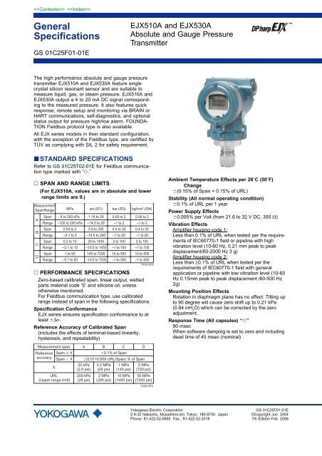
EJX510A and EJX530A<br />
Absolute and Gauge <strong>Pressure</strong><br />
<strong>Transmitter</strong><br />
The high performance absolute and gauge pressure<br />
transmitter EJX510A and EJX530A feature single<br />
crystal silicon resonant sensor and are suitable to<br />
measure liquid, gas, or steam pressure. EJX510A and<br />
EJX530A output a 4 to 20 mA DC signal corresponding<br />
to the measured pressure. It also features quick<br />
response, remote setup and monitoring via BRAIN or<br />
HART communications, self-diagnostics, and optional<br />
status output for pressure high/low alarm. FOUNDA-<br />
TION Fieldbus protocol type is also available.<br />
All EJX series models in their standard configuration,<br />
with the exception of the Fieldbus type, are certified by<br />
TÜV as complying with SIL 2 for safety requirement.<br />
STANDARD SPECIFICATIONS<br />
Refer to GS 01C25T02-01E for Fieldbus communication<br />
type marked with “.”<br />
SPAN AND RANGE LIMITS<br />
(For EJX510A, values are in absolute and lower<br />
range limits are 0.)<br />
Measurement<br />
Span/Range MPa psi (/D1) bar (/D3) kgf/cm 2 (/D4)<br />
A<br />
B<br />
C<br />
D<br />
Span<br />
Span<br />
Span<br />
Span<br />
8 to 200 kPa<br />
0.04 to 2<br />
0.2 to 10<br />
1 to 50<br />
1.16 to 29<br />
5.8 to 290<br />
29 to 1450<br />
145 to 7200<br />
0.08 to 2<br />
0.4 to 20<br />
2 to 100<br />
10 to 500<br />
0.08 to 2<br />
0.4 to 20<br />
2 to 100<br />
10 to 500<br />
Range<br />
Range<br />
Range<br />
Range<br />
–100 to 200 kPa<br />
–0.1 to 2<br />
–0.1 to 10<br />
–0.1 to 50<br />
–14.5 to 29<br />
–14.5 to 290<br />
–14.5 to 1450<br />
–14.5 to 7200<br />
–1 to 2<br />
–1 to 20<br />
–1 to 100<br />
–1 to 500<br />
–1 to 2<br />
–1 to 20<br />
–1 to 100<br />
–1 to 500<br />
T01E.EPS<br />
PERFORMANCE SPECIFICATIONS<br />
Zero-based calibrated span, linear output, wetted<br />
parts material code ‘S’ and silicone oil, unless<br />
otherwise mentioned.<br />
For Fieldbus communication type, use calibrated<br />
range instead of span in the following specifications.<br />
Specification Conformance<br />
EJX series ensures specification conformance to at<br />
least 3.<br />
Reference Accuracy of Calibrated Span<br />
(includes the effects of terminal-based linearity,<br />
hysteresis, and repeatability)<br />
Ambient Temperature Effects per 28˚C (50˚F)<br />
Change<br />
(0.15% of Span + 0.15% of URL)<br />
Stability (All normal operating condition)<br />
0.1% of URL per 1 year<br />
Power Supply Effects<br />
0.005% per Volt (from 21.6 to 32 V DC, 350 )<br />
Vibration Effects<br />
Amplifier housing code 1:<br />
Less than 0.1% of URL when tested per the requirements<br />
of IEC60770-1 field or pipeline with high<br />
vibration level (10-60 Hz, 0.21 mm peak to peak<br />
displacement/60-2000 Hz 3 g)<br />
Amplifier housing code 2:<br />
Less than ±0.1% of URL when tested per the<br />
requirements of IEC60770-1 field with general<br />
application or pipeline with low vibration level (10-60<br />
Hz 0.15mm peak to peak displacement /60-500 Hz<br />
2g)<br />
<strong>Mount</strong>ing Position Effects<br />
Rotation in diaphragm plane has no effect. Tilting up<br />
to 90 degree will cause zero shift up to 0.21 kPa<br />
(0.84 inH 2<br />
O) which can be corrected by the zero<br />
adjustment.<br />
Response Time (All capsules) “”<br />
90 msec<br />
When software damping is set to zero and including<br />
dead time of 45 msec (nominal)<br />
Measurement span<br />
Reference Span X<br />
accuracy Span X<br />
X<br />
URL<br />
(Upper range limit)<br />
A<br />
20 kPa<br />
(2.9 psi)<br />
200 kPa<br />
(29 psi)<br />
B<br />
0.1% of Span<br />
(0.01+0.009 URL/Span) % of Span<br />
0.2 MPa<br />
(29 psi)<br />
2 MPa<br />
(290 psi)<br />
C<br />
1 MPa<br />
(145 psi)<br />
10 MPa<br />
(1450 psi)<br />
D<br />
5 MPa<br />
(720 psi)<br />
50 MPa<br />
(7200 psi)<br />
T02E.EPS<br />
Yokogawa Electric Corporation<br />
2-9-32 Nakacho, Musashino-shi, Tokyo, 180-8750 Japan<br />
Phone: 81-422-52-5690 Fax.: 81-422-52-2018<br />
GS 01C25F01-01E<br />
©Copyright Jun. 2004<br />
7th Edition Feb. 2006
FUNCTIONAL SPECIFICATIONS<br />
Output<br />
Two wire 4 to 20 mA DC output with digital communications,<br />
linear or square root programmable. BRAIN<br />
or HART FSK protocol are superimposed on the 4 to<br />
20 mA signal.<br />
Output range: 3.6 mA to 21.6 mA<br />
Output limits conforming to NAMUR NE43 can be<br />
pre-set by option code C2 or C3.<br />
Failure Alarm (Output signal code D and E)<br />
Output status at CPU failure and hardware error;<br />
Up-scale: 110%, 21.6 mA DC or more (standard)<br />
Down-scale: 5%, 3.2 mA DC or less<br />
Damping Time Constant (1st order)<br />
Amplifier’s damping time constant is adjustable from<br />
0.00 to 100.00 sec by software and added to response<br />
time.<br />
Note: For BRAIN protocol type, when the software<br />
damping is set to less than 0.5 sec, communication<br />
may occasionally be unavailble during the<br />
operation, especially while output changes<br />
dynamically. The default setting of damping<br />
ensures stable communication.<br />
Update Period “”<br />
<strong>Pressure</strong>: 45 msec<br />
Zero Adjustment Limits<br />
Zero can be fully elevated or suppressed, within the<br />
lower and upper range limits of the capsule.<br />
External zero Adjustment<br />
External zero is continuously adjustable with 0.01%<br />
incremental resolution of span. Re-range can be<br />
done locally using the digital indicator with rangesetting<br />
switch.<br />
Integral Indicator (LCD display, optional) “”<br />
5-digit numerical display, 6-digit unit display and bar<br />
graph.<br />
The indicator is configurable to display one or up to<br />
three of the following variables periodically;<br />
pressure in %, scaled pressure, measured pressure.<br />
See also “Factory Settings.”<br />
Burst <strong>Pressure</strong><br />
A, B and C capsule : 30 MPa<br />
D capsule : 132 MPa<br />
Self Diagnostics<br />
CPU failure, hardware failure, configuration error,<br />
process alarm for pressure or capsule temperature.<br />
User-configurable process high/low alarm for<br />
pressure is also available, and its status can be<br />
output when optional status output is specified.<br />
Signal Characterizer (Output signal code D and E)<br />
User-configurable 10-segment signal characterizer<br />
for 4 to 20 mA output.<br />
Status Output (optional, output signal code D and E)<br />
One transistor contact output (sink type) to output the<br />
status of user configurable high/low alarm for<br />
pressure.<br />
Rating: 10.5 to 30 V DC, 120 mA DC max.<br />
Note: A check meter cannot be connected when status<br />
output option (/AL) is specified.<br />
Refer to ‘Wiring Example for Analog Output and<br />
Status Output.’<br />
SIL Certification<br />
EJX series transmitters except Fieldbus communication<br />
type are certified by RWTÜV Systems GmbH in<br />
compliance with the following standards;<br />
IEC 61508: 2000; Part1 to Part 7<br />
Functional Safety of Electrical/electronic/programmable<br />
electronic related systems; SIL 2 capability for<br />
single transmitter use, SIL 3 capability for dual<br />
transmitter use.<br />
NORMAL OPERATING CONDITION<br />
(Optional features or approval codes may affect<br />
limits.)<br />
Ambient Temperature Limits<br />
40 to 85˚C (40 to 185˚F)<br />
30 to 80˚C (22 to 176˚F) with LCD display<br />
Process Temperature Limits<br />
40 to 120˚C (40 to 248˚F)<br />
Ambient Humidity Limits<br />
0 to 100% RH<br />
Maximum Over <strong>Pressure</strong><br />
<strong>Pressure</strong><br />
Capsule EJX510A EJX530A<br />
A and B 4 MPa abs (580 psia) 4 MPa (580 psig)<br />
C 20 MPa abs (2900 psia) 20 MPa (2900 psig)<br />
D 75 MPa abs (10800 psia) 75 MPa (10800 psig)<br />
Working <strong>Pressure</strong> Limits (Silicone oil)<br />
Maximum <strong>Pressure</strong> Limits<br />
<strong>Pressure</strong><br />
Capsule EJX510A EJX530A<br />
A 200 kPa abs (29 psia) 200 kPa (29 psig)<br />
B 2 MPa abs (290 psia) 2 MPa (290 psig)<br />
C 10 MPa abs (1450 psia) 10 MPa (1450 psig)<br />
D 50 MPa abs (7200 psia) 50 MPa (7200 psig)<br />
2<br />
All Rights Reserved. Copyright © 2004, Yokogawa Electric Corporation<br />
GS 01C25F01-01E Aug. 31, 2005-00
3<br />
Minimum <strong>Pressure</strong> Limit<br />
See graph below<br />
100(750)<br />
600<br />
10(75)<br />
External<br />
load<br />
resistance<br />
R=<br />
E-10.5<br />
0.0244<br />
Digital<br />
Communication<br />
range<br />
BRAIN and HART<br />
Working<br />
2.7(20)<br />
pressure<br />
kPa abs 1(7.5)<br />
(mmHg abs)<br />
Applicable range<br />
R ()<br />
250<br />
0.13(1)<br />
0.1(0.75)<br />
0.013(0.1)<br />
0.01(0.075)<br />
-40<br />
(-40)<br />
0<br />
(32)<br />
40<br />
(104)<br />
80<br />
(176)<br />
Process temperature C(F)<br />
120 (248)<br />
85<br />
(185)<br />
F01E.EPS<br />
Figure 1-1. Working <strong>Pressure</strong> and Process Temperature<br />
[For EJX510A]<br />
100(14.5)<br />
Working<br />
pressure<br />
kPa abs<br />
(psia)<br />
10(1.4)<br />
2.7(0.38)<br />
1(0.14)<br />
-40<br />
(-40)<br />
Applicable range<br />
0<br />
(32)<br />
40<br />
(104)<br />
80<br />
(176)<br />
Process temperature C (F)<br />
Atmospheric<br />
pressure<br />
120<br />
(248)<br />
F02E.EPS<br />
Figure 1-2. Working <strong>Pressure</strong> and Process Temperature<br />
[For EJX530A]<br />
10.5 16.6 25.2 42<br />
Power supply voltage E (V DC)<br />
Figure 2. Relationship Between Power Supply Voltage<br />
and External Load Resistance<br />
F03E.EPS<br />
Supply Voltage “”<br />
10.5 to 42 V DC for general use and flameproof type.<br />
10.5 to 32 V DC for lightning protector (option code A).<br />
10.5 to 30 V DC for intrinsically safe, type n, nonincendive<br />
or non-sparking type.<br />
Minimum voltage limited at 16.6 V DC for digital<br />
communications, BRAIN and HART<br />
Load (Output signal code D and E)<br />
0 to 1290 for operation<br />
250 to 600 for digital communication<br />
Communication Requirements “”<br />
(Approval codes may affect electrical requirements.)<br />
BRAIN<br />
Communication Distance<br />
Up to 2 km (1.25 miles) when using CEV polyethylene-insulated<br />
PVC-sheathed cables. Communication<br />
distance varies depending on type of cable used.<br />
Load Capacitance<br />
0.22 F or less<br />
Load Inductance<br />
3.3 mH or less<br />
Input Impedance of communicating device<br />
10 k or more at 2.4 kHz.<br />
Supply & Load Requirements<br />
(Output signal code D and E. Optional features<br />
or approval codes may affect electrical requirements.)<br />
With 24 V DC supply, up to a 550 load can be<br />
used. See graph below.<br />
All Rights Reserved. Copyright © 2004, Yokogawa Electric Corporation<br />
GS 01C25F01-01E Aug. 31, 2005-00
HART<br />
Communication Distance<br />
Up to 1.5 km (1 mile) when using multiple twisted pair<br />
cables. Communication distance varies depending on<br />
type of cable used.<br />
Use the following formula to determine cable length<br />
for specific applications:<br />
65 10 6<br />
L= -<br />
(R C)<br />
(C f + 10,000)<br />
C<br />
Where:<br />
L = length in meters or feet<br />
R = resistance in (including barrier resistance)<br />
C = cable capacitance in pF/m or pF/ft<br />
C f<br />
= maximum shunt capacitance of receiving devices<br />
in pF/m or pF/ft<br />
EMC Conformity Standards ,<br />
EN 61326, AS/NZS CISPR11<br />
European <strong>Pressure</strong> Equipment <strong>Direct</strong>ive 97/23/EC<br />
Sound Engineering Practice (for all capsules)<br />
< Related Instruments><br />
Power Distributor: Refer to GS 01B04T01-02E or<br />
GS 01B04T02-02E<br />
BRAIN TERMINAL: Refer to GS 01C00A11-00E<br />
< Reference ><br />
1. Hastelloy; Trademark of Haynes International Inc.<br />
2. HART; Trademark of the HART Communication<br />
Foundation.<br />
3. FOUNDATION Fieldbus; Tradmark of Fieldbus<br />
Foundation.<br />
Other company names and product names used in this<br />
material are registered trademarks or trademarks of<br />
their respective owners.<br />
4<br />
With option code /PE3 (for D capsule)<br />
Category III, Module H, Type of Equipment: <strong>Pressure</strong><br />
Accessory-Vessel, Type of Fluid: Liquid and Gas,<br />
Group of Fluid: 1 and 2<br />
PHYSICAL SPECIFICATIONS<br />
Wetted Parts Materials<br />
Diaphragm, Process Connector<br />
Refer to “MODEL AND SUFFIX CODE.”<br />
Non-wetted Parts Materials<br />
Housing<br />
Low copper cast aluminum alloy with polyurethane,<br />
mint-green paint (Munsell 5.6BG 3.3/2.9 or its<br />
equivalent) or ASTM CF-8M Stainless Steel<br />
Degrees of Protection<br />
IP67, NEMA4X, JIS C0920<br />
Pipe<br />
Polypropylene<br />
Cover O-rings<br />
Buna-N<br />
Name plate and tag<br />
304 SST<br />
Fill Fluid<br />
Silicone, fluorinated oil (option)<br />
Weight<br />
Capsule A, B and C: 1.1 kg (2.4 lb)*<br />
Capsule D: 1.3 kg (2.9 lb)*<br />
*: Without integral indicator and mounting bracket.<br />
Add 1.5 kg (3.3lb) for Amplifier housing code 2.<br />
Connections<br />
Refer to “MODEL AND SUFFIX CODE.”<br />
All Rights Reserved. Copyright © 2004, Yokogawa Electric Corporation<br />
GS 01C25F01-01E Aug. 31, 2005-00
5<br />
MODEL AND SUFFIX CODES<br />
Model<br />
EJX510A<br />
EJX530A<br />
Output signal<br />
Measurement<br />
span (Capsule)<br />
Wetted parts<br />
material * 4<br />
Process connections<br />
—<br />
—<br />
Amplifier housing<br />
Electrical connection<br />
Integral indicator<br />
<strong>Mount</strong>ing bracket<br />
Optional code<br />
Suffix Codes<br />
· · · · · · · · · · · · · · · · · · · · · · · ·<br />
· · · · · · · · · · · · · · · · · · · · · · · ·<br />
-D · · · · · · · · · · · · · · · · · · · · · ·<br />
-E · · · · · · · · · · · · · · · · · · · · · ·<br />
-F · · · · · · · · · · · · · · · · · · · · · ·<br />
A · · · · · · · · · · · · · · · · · · · · ·<br />
B · · · · · · · · · · · · · · · · · · · · ·<br />
C · · · · · · · · · · · · · · · · · · · · ·<br />
D · · · · · · · · · · · · · · · · · · · · ·<br />
S · · · · · · · · · · · · · · · · · ·<br />
H · · · · · · · · · · · · · · · · · ·<br />
4 · · · · · · · · · · · · · · · · ·<br />
7 · · · · · · · · · · · · · · · · ·<br />
8 · · · · · · · · · · · · · · · · ·<br />
9 · · · · · · · · · · · · · · · · ·<br />
N · · · · · · · · · · · · · · ·<br />
-0 · · · · · · · · · · · · ·<br />
<br />
<br />
1 · · · · · · · · · · · ·<br />
2 · · · · · · · · · · · ·<br />
0 · · · · · · · · ·<br />
<br />
2 · · · · · · · · ·<br />
4 · · · · · · · · ·<br />
5 · · · · · · · · ·<br />
7 · · · · · · · · ·<br />
9 · · · · · · · · ·<br />
<br />
D · · · · · · ·<br />
E · · · · · · ·<br />
N · · · · · · ·<br />
F · · · · · ·<br />
N · · · · · ·<br />
Description<br />
Absolute pressure transmitter<br />
Gauge pressure transmitter<br />
4 to 20 mA DC Output with digital communication (BRAIN protocol)<br />
4 to 20 mA DC Output with digital communication (HART protocol)<br />
Digital communication (FOUNDATION Fieldbus protocol, refer to GS 01C25T02-01E)<br />
8 to 200 kPa (1.16 to 29 psi)<br />
0.04 to 2 MPa (5.8 to 290 psi)<br />
0.2 to 10 MPa (29 to 1450 psi)<br />
1 to 50 MPa (145 to 7200 psi)<br />
Process connection Diaphragm<br />
316L SST # Hastelloy C-276 * 1#<br />
Hastelloy C-276 * 1# Hastelloy C-276 * 1#<br />
1/2 NPT female<br />
1/2 NPT male<br />
G1/2 DIN 16 288 male * 2<br />
M201.5 DIN 16 288 male * 2<br />
Always N<br />
Always 0<br />
Cast alluminum alloy<br />
ASTM CF-8M Stainless Steel * 5<br />
G1/2 female, one electrical connection without blind plugs<br />
1/2 NPT female, two electrical connections without blind plugs<br />
M20 female, two electrical connections without blind plugs<br />
G1/2 female, two electrical connections with a blind plug<br />
1/2 NPT female, two electrical connections with a blind plug<br />
M20 female, two electrical connections with a blind plug<br />
Digital indicator<br />
Digital indicator with the range setting switch * 3<br />
None<br />
304 SST 2-inch pipe mounting<br />
None<br />
/ Optional specification<br />
The “” marks indicates the most typical selection for each specification. Example: EJX530A-DAS4N-012NN/.<br />
*1: Hastelloy C-276 or ASTM N10276.<br />
*2: Not applicable for combination of capsule code D and wetted parts material code H.<br />
*3: Not applicable for output signal code F.<br />
*4: Users must consider the characteristics of selected wetted parts material and the influence of process fluids. The use of<br />
inappropriate materials can result in the leakage of corrosive process fluids and cause injury to personnel and/or<br />
damage to plant facilities. It is also possible that the diaphragm itself can be damaged and that material from the broken<br />
diaphragm and the fill fluid can contaminate the user’s process fluids.<br />
Be very careful with highly corrosive process fluids such as hydrochloric acid, sulfuric acid, hydrogen sulfide, sodium<br />
hypochlorite, and high-temperature steam (150°C [302°F] or above). Contact Yokogawa for detailed information of the<br />
wetted parts material.<br />
*5: Not applicable for electrical connection code 0.<br />
# The ‘#’marks indicate the construction materials conform to NACE material recommendations per MR01-75. For the use<br />
of 316 SST material, there may be certain limitations for pressure and temperature. Please refer to NACE standards for<br />
details.<br />
T03.EPS<br />
All Rights Reserved. Copyright © 2004, Yokogawa Electric Corporation GS 01C25F01-01E Feb. 10, 2006-00
6<br />
OPTIONAL SPECIFICATIONS (For Explosion Protected type) “”<br />
Item Description Code<br />
Factory<br />
Mutual<br />
(FM)<br />
CENELEC<br />
ATEX<br />
FM Explosionproof Approval * 1<br />
Applicable Standard: FM3600, FM3615, FM3810, ANSI/NEMA 250<br />
Explosionproof for Class I, Division 1, Groups B, C and D, Dust-ignitionproof for Class II/III, Division 1,<br />
Groups E, F and G, in Hazardous locations, indoors and outdoors (NEMA 4X)<br />
Temperature class: T6, Amb. Temp.: –40 to 60C (–40 to 140F)<br />
FM Intrinsically safe Approval * 1 * 2<br />
Applicable Standard: FM3600, FM3610, FM3611, FM3810<br />
Intrinsically Safe for Class I, Division 1, Groups A, B, C & D, Class II, Division 1,<br />
Groups E, F & G and Class III, Division 1, Class I, Zone 0, in Hazardous Locations, AEx ia IIC<br />
Nonincendive for Class I, Division 2, Groups A, B, C & D, Class II, Division. 2,<br />
Groups F & G, and Class III, Division 1, Class I, Zone 2, Group IIC, in Hazardous Locations<br />
Enclosure: "NEMA 4X", Temp. Class: T4, Amb. Temp.: –60 to 60C (–75 to 140F)<br />
Intrinsically Safe Apparatus Parameters<br />
[Groups A, B, C, D, E, F and G] Vmax=30 V, Imax=200 mA, Pmax=1 W, Ci=6 nF, Li=0 H<br />
[Groups C, D, E, F and G] Vmax=30 V, Imax=225 mA, Pmax=1 W, Ci=6 nF, Li=0 H<br />
Combined FF1 and FS1 * 1 * 2<br />
CENELEC ATEX (KEMA) Flameproof Approval * 1<br />
Applicable Standard: EN 50014, EN 50018, EN 50281-1-1<br />
Certificate: KEMA 03ATEX2570<br />
II 2G,1D EExd IIC T4, T5, T6 Type of protection : IP66 and IP67<br />
Amb. Temp. (Tamb) for gas-proof :<br />
T4 ; –50 to 75°C (–58 to 167°F), T5; –50 to 80C (–58 to 176F), T6; –50 to 70°C (–58 to 158°F)<br />
Max. process Temp.(Tp): T4; 120C (248F), T5; 100C (212F), T6; 85C (185F)<br />
Max. surface Temp. for dust-proof : T80°C (Tamb: –40 to 40C, Tp:80C),<br />
T100°C (Tamb: –40 to 60C, Tp:100C), T120°C (Tamb: –40 to 80C, Tp:120C)<br />
CENELEC ATEX (KEMA) Intrinsically safe Approval * 1 * 2<br />
Applicable Standard: EN 50014, EN 50020, EN 50284, EN 50281-1-1<br />
Certificate: KEMA 03ATEX1544X<br />
II 1G, 1D EEx ia IIC T4 Type of protection : IP66 and IP67<br />
Amb. Temp.(Tamb) for gas-proof: –50 to 60C (–58 to 140F)<br />
Maximum Process Temp.(Tp) for gas-proof :120C<br />
Electrical data : Ui=30 V, Ii=200 mA, Pi=0.9 W, Ci=10 nF, Li=0 mH<br />
Max. surface Temp. for dust-proof : T85°C (Tamb: –40 to 60C, Tp:80C),<br />
T100°C (Tamb: –40 to 60C, Tp:100C), T120°C (Tamb: –40 to 60C, Tp:120C)<br />
Combined KF2, KS2 and Type n * 1 * 2<br />
Type n<br />
Applicable Standard: EN 50021, EN 60529<br />
II 3G EEx nL IIC T4, Amb. Temp.: –50 to 60C (–50 to 140F)<br />
Ui=30 V DC, Ci=10 nF, Li=0 mH<br />
*1: Applicable for electrical connection code 2, 4, 7, and 9.<br />
*2: Not applicable for option code /AL.<br />
FF1<br />
FS1<br />
FU1<br />
KF2<br />
KS2<br />
KU2<br />
T04E.EPS<br />
All Rights Reserved. Copyright © 2004, Yokogawa Electric Corporation<br />
GS 01C25F01-01E Feb. 10, 2006-00
7<br />
Item Description Code<br />
Canadian<br />
Standards<br />
Association<br />
(CSA)<br />
CSA Explosionproof Approval * 2<br />
Certificate: 1589701<br />
[For CSA C22.2]<br />
Applicable Standard: C22.2 No.0, C22.2 No.0.4, C22.2 No.0.5, C22.2 No.25, C22.2 No.30,<br />
C22.2 No.94<br />
Explosion-proof for Class I, Groups B, C and D.<br />
Dustignition-proof for Class II/III, Groups E, F and G.<br />
When installed in Division 2, “SEAL NOT REQUIRED” Enclosure: TYPE 4X, Temp. Code: T6...T4<br />
[For CSA E60079]<br />
Applicable Standard: CAN/CSA E60079-0, CAN/CSA E60079-1<br />
Flameproof for Zone 1, Ex d IIC T6...T4 Enclosure: IP66 and IP67<br />
Max.Process Temp.: T4;120C(248F), T5;100C(212 F), T6; 85C(185F)<br />
Amb.Temp.:–50 to 75C(–58 to 167F) for T4, –50 to 80C(–58 to 176F) for T5,<br />
–50 to 70C(–58 to 158F) for T6<br />
CSA Intrinsically safe Approval * 2 * 3<br />
Certificate: 1606623<br />
[For CSA C22.2]<br />
Applicable Standard: C22.2 No.0, C22.2 No.0.4, C22.2 No.25, C22.2 No.94, C22.2 No.154,<br />
C22.2 No.213, C22.2 No.1010.1<br />
Intrinsically Safe for Class I, Division 1, Groups A, B, C & D, Class II, Division 1, Groups E, F & G,<br />
Class III, Division 1, Nonincendive for Class I, Division 2, Groups A, B, C & D, Class II, Division 2,<br />
Groups E, F & G, Class III, Division 1<br />
Enclosure: Type 4X, Temp. Code: T4 Amb. Temp.:–50 to 60C(–58 to 140F)<br />
Electrical Parameters: [Intrinsically Safe] Vmax=30V, Imax=200mA, Pmax=0.9W, Ci=10nF, Li=0<br />
[Nonincendive] Vmax=30V, Ci=10nF, Li=0<br />
[For CSA E60079]<br />
Applicable Standard: CAN/CSA E60079-0, CAN/CSA E60079-11, CAN/CSA E60079-15,<br />
IEC 60529:2001-02<br />
Ex ia IIC T4, Ex nL IIC T4 Enclosure: IP66 and IP67<br />
Amb. Temp.:–50 to 60C(–58 to 140F), Max. Process Temp.: 120C(248F)<br />
Electrical Parameters: [Ex ia] Ui=30V, Ii=200mA, Pi=0.9W, Ci=10nF, Li=0<br />
[Ex nL] Ui=30V, Ci=10nF, Li=0<br />
CF1<br />
CS1<br />
IECEx<br />
Scheme * 4<br />
Combined CF1 and CS1 * 2 * 3<br />
IECEx Intrinsically safe, type n and Flameproof Approval * 1 * 3<br />
Intrinsically safe and type n<br />
Applicable Standard: IEC 60079-0:2000, IEC 60079-11:1999, IEC 60079-15:2001<br />
Certificate: IECEx CSA 05.0005<br />
Ex ia IIC T4, Ex nL IIC T4 Enclosure: IP66 and IP67<br />
Amb. Temp.:–50 to 60C(–58 to 140F), Max. Process Temp.: 120C(248F)<br />
Electrical Parameters: [Ex ia] Ui=30V, Ii=200mA, Pi=0.9W, Ci=10nF, Li=0<br />
[Ex nL] Ui=30V,Ci=10nF, Li=0<br />
Flameproof<br />
Applicable Standard: IEC 60079-0:2000, IEC60079-1:2001<br />
Certificate: IECEx CSA 05.0002<br />
Flameproof for Zone 1, Ex d IIC T6...T4 Enclosure: IP66 and IP67<br />
Max.Process Temp.: T4;120C(248F), T5;100C(212F), T6; 85C(185F)<br />
Amb.Temp.:–50 to 75C(–58 to 167F) for T4, –50 to 80C(–58 to 176F) for T5,<br />
–50 to 70C(–58 to 158F) for T6<br />
CU1<br />
SU2<br />
*1: Applicable for electrical connection code 2, 4, 7, and 9.<br />
*2: Applicable for electrical connection code 2 and 7.<br />
*3: Not applicable for output signal code -F and option code /AL.<br />
*4: Applicable only for Australia and New Zealand area.<br />
T04Eb.EPS<br />
All Rights Reserved. Copyright © 2004, Yokogawa Electric Corporation GS 01C25F01-01E Aug. 31, 2005-00
8<br />
OPTIONAL SPECIFICATIONS<br />
Description<br />
Amplifier cover only *14<br />
Color change<br />
Painting<br />
Amplifier cover and terminal cover, Munsell 7.5 R4/14<br />
Coating change Anti-corrosion coating *1*14<br />
<strong>Transmitter</strong> power supply voltage: 10.5 to 32 V DC ( 10.5 to 30 V DC for intrinsically<br />
safe type, 9 to 32 V DC for Fieldbus communication type.)<br />
Lightning protector<br />
Allowable current: Max. 6000 A ( 140 s ), Repeating 1000 A ( 140 s ) 100 times<br />
Applicable Standards: IEC 61000-4-4, IEC 61000-4-5<br />
Status output * 2<br />
Item<br />
Oil-prohibited use *13<br />
Capsule fill fluid<br />
Calibration units *3<br />
Output limits<br />
and failure operation *4<br />
Stainless steel tag plate<br />
Data configuration at factory *5<br />
European <strong>Pressure</strong> Equipment<br />
<strong>Direct</strong>ive *15<br />
Material certificate *6<br />
<strong>Pressure</strong> test<br />
/Leak test certificate *12<br />
Transistor output (sink type)<br />
Rating: 10.5 to 30 V DC, 120 mA DC (max)<br />
Degrease cleansing treatment<br />
Degrease cleansing treatment and with fluorinated oilfilled capsule.<br />
Operating temperature –20 to 80°C (–4 to 176°F)<br />
Fluorinated oil filled in capsule<br />
P calibration (psi unit)<br />
(See Table for Span and<br />
bar calibration (bar unit)<br />
Range Limits.)<br />
M calibration (kgf/cm 2 unit)<br />
Failure alarm down-scale: Output status at CPU failure and hardware error is –5%,<br />
3.2mA DC or less.<br />
NAMUR NE43 Compliant<br />
Output signal limits: 3.8mA to<br />
20.5 mA<br />
Low level: 0 to 2 V DC<br />
Failure alarm down-scale: Output status at CPU<br />
failure and hardware error is –5%, 3.2mA DC or less.<br />
Failure alarm up-scale: Output status at CPU<br />
failure and hardware error is 110%, 21.6 mA or more.<br />
304 SST stainless steel tag plate wired onto transmitter<br />
Data configuration for HART communication type Software damping, Descriptor, Message<br />
Data configuration for BRAIN communication type Software damping<br />
PED 97/23/EC<br />
Category III, Module H, Type of Equipment: <strong>Pressure</strong> Accessory-Vessel,<br />
Type of Fluid: Liquid and Gas, Group of Fluid: 1 and 2<br />
Process Connector<br />
Test <strong>Pressure</strong>: 200 kPa (29 psi) *7<br />
Test <strong>Pressure</strong>: 2 MPa (290 psi) *8<br />
Nitrogen(N 2 ) Gas or Water *11<br />
Test <strong>Pressure</strong>: 10 MPa (1450 psi) *9<br />
Retention time: one minute<br />
Test <strong>Pressure</strong>: 50 MPa (7200 psi) *10<br />
*1: Not applicable with color change option.<br />
*2: Check/External indicator terminals cannot be used when this option code is specified. Not applicable for output signal<br />
code F and amplifier housing code 2.<br />
*3: The unit of MWP (Max. working pressure) on the name plate of a housing is the same unit as specified by option codes<br />
D1, D3, and D4.<br />
*4: Applicable for output signal codes D and E. The hardware error indicates faulty amplifier or capsule.<br />
*5: Also see ‘Ordering Information’.<br />
*6: Material traceability certification, per EN 10204 3.1 B.<br />
*7: Applicable for capsule code A.<br />
*8: Applicable for capsule code B.<br />
*9: Applicable for capsule code C.<br />
*10: Applicable for capsule code D.<br />
*11: Pure nitrogen gas or pure water is used for oil-prohibited use (option codes K1 and K2).<br />
*12: The unit on the certificate is always kPa/MPa regardless of selection of option code D1, D3 and D4.<br />
*13: Applicable for wetted parts material code S.<br />
*14: Not applicable for amplifier housing code 2.<br />
*15: Applicable for measurement span code D. If compliance with category III is needed, specify this option code.<br />
Code<br />
P<br />
PR<br />
X2<br />
A<br />
AL<br />
K1<br />
K2<br />
K3<br />
D1<br />
D3<br />
D4<br />
C1<br />
C2<br />
C3<br />
N4<br />
CA<br />
CB<br />
PE3<br />
M15<br />
T05<br />
T06<br />
T07<br />
T08<br />
T05.EPS<br />
All Rights Reserved. Copyright © 2004, Yokogawa Electric Corporation<br />
GS 01C25F01-01E Aug. 31, 2005-00
9<br />
DIMENSIONS<br />
Model EJX510A and EJX530A<br />
With process connections code 7<br />
Unit: mm (Approx. inch)<br />
95(3.74)<br />
60(2.36) *2<br />
188(7.4)<br />
External indicator<br />
Conduit connection<br />
(optional)<br />
54<br />
(2.13)<br />
Conduit<br />
connection<br />
Zero<br />
adjustment<br />
110(4.33)<br />
12<br />
(0.47)<br />
39<br />
(1.54)<br />
6<br />
(0.23)<br />
Electrical connection<br />
for code 5 and 9.<br />
129(5.08)<br />
Integral<br />
indicator<br />
(optional)<br />
163(6.42)<br />
Shrouding bolt<br />
(for flame-proof type)<br />
169(6.65)<br />
ø77(3.03)<br />
Ground<br />
terminal<br />
ø69<br />
(2.72)<br />
110(4.33)<br />
<strong>Mount</strong>ing<br />
bracket<br />
(optional)<br />
12 *3<br />
(0.47)<br />
2-inch pipe<br />
(O.D. 60.5mm)<br />
Pipe for<br />
open to<br />
atmosphere *1<br />
129(5.08)<br />
*1: Only for EJX530A whose measurement span code is A, B, or C.<br />
*2: 58 mm (2.28 inch) for measurement span code D.<br />
*3: 11 mm (0.43 inch) for measurement span code D.<br />
With process connections code 4<br />
With process connections code 8 and 9<br />
20(0.78)<br />
174(6.85) 158(6.22)<br />
5(0.20)<br />
ø6(0.23)<br />
F04.EPS<br />
● Terminal Configuration<br />
Communication<br />
terminals (BT200 etc.)<br />
connection hook<br />
Check meter<br />
connection hook *4*5<br />
● Terminal Wiring<br />
SUPPLY<br />
CHECK<br />
or<br />
ALARM<br />
+<br />
–<br />
+<br />
–<br />
+<br />
–<br />
Power supply and output terminal<br />
External indicator (ammeter) terminal *4*5<br />
or<br />
Status contact output terminal *5<br />
(when /AL is specified)<br />
SUPPLY +<br />
CHECK + or<br />
ALARM +<br />
SUPPLY – CHECK – or ALARM –<br />
Ground terminal<br />
*4: When using an external indicator or check meter, the internal<br />
resistance must be 10 or less. A check meter or indicator<br />
cannot be connected when /AL option is specified.<br />
*5: Not available for fieldbus communication type.<br />
F05.EPS<br />
All Rights Reserved. Copyright © 2004, Yokogawa Electric Corporation<br />
GS 01C25F01-01E Feb. 10, 2006-00
10<br />
● Wiring Example for Analog Output and Status Output<br />
Description<br />
Connection<br />
Analog output<br />
EJX electrical terminal<br />
SUPPLY<br />
CHECK<br />
+<br />
–<br />
+<br />
+<br />
–<br />
Distributor<br />
24V DC<br />
250Ω<br />
Analog and<br />
status output<br />
(when /AL is specified)<br />
If shield cable is not<br />
used, communication is<br />
not possible.<br />
EJX electrical terminal<br />
SUPPLY<br />
ALARM<br />
+<br />
–<br />
+<br />
Shielded cable<br />
+<br />
–<br />
24V DC<br />
250Ω<br />
External power supply<br />
30V DC, 120mA max<br />
Distributor<br />
Magnetic<br />
valve<br />
Use two-wire separately shielded cables.<br />
AC power supply<br />
F06.EPS<br />
< Ordering Information > “”<br />
Specify the following when ordering<br />
1. Model, suffix codes, and option codes<br />
2. Calibration range and units<br />
1) Calibration range can be specified with range<br />
value specifications up to 5 digits<br />
(excluding any decimal point) for low or high range<br />
limits within the range of -32000 to 32000. When<br />
reverse range is designated, specify Lower Range<br />
Value (LRV) as greater than Upper Range Value<br />
(URV).<br />
2) Specify only one unit from the table, ‘Factory<br />
Settings’ when shipped.’<br />
3. Display scale and units (for transmitters equipped<br />
with integral indicator only)<br />
Specify either 0 to 100 % or engineering unit scale<br />
and ‘Range and Unit’ for engineering units scale:<br />
Scale range can be specified with range limit<br />
specifications up to 5 digits (excluding any decimal<br />
point) for low or high range limits within the range of<br />
-32000 to 32000. The unit display consists of 6-digit,<br />
therefore, if the specified unit is longer than 7<br />
characters excluding ‘/’, the first 6 characters will be<br />
displayed on the unit display.<br />
4. Tag Number (if required)<br />
For BRAIN communication type, specify upto 16<br />
letters. The specified letters will be written in the<br />
amplifier memory and engraved on the tag plate.<br />
For HART communication type, specify software tag<br />
(up to 8 letters) to be written on the amplifier memory<br />
and Tag number(up to 16 letters) to be engraved on<br />
the tag plate seperately.<br />
5. Other factory configurations (if required)<br />
Specifying option code CA or CB will allow further<br />
configuration at factory. Following are configurable<br />
items and setting range.<br />
[/CA: For HART communication type]<br />
1) Descriptor(up to 16 characters)<br />
2) Message (up to 30 characters)<br />
3) Software damping in second (0.00 to 100.00)<br />
[/CB: For BRAIN communication type]<br />
1) Software damping in second (0.00 to 100.00)<br />
< Factory Setting > “”<br />
Tag number<br />
Software<br />
damping *1<br />
Calibration range<br />
lower range value<br />
Calibration range<br />
upper range value<br />
Calibration range<br />
units<br />
Display setting<br />
As specified in order<br />
‘2.00 sec’ or as specified in order<br />
As specified in order<br />
As specified in order<br />
[EJX530A]<br />
Selected from mmH 2 O, mmH 2 O(68˚F),<br />
mmAq *2 , mmWG *2 , mmHg, Pa, hPa *2 ,<br />
kPa, MPa, mbar, bar, gf/cm 2 , kgf/cm 2 ,<br />
inH 2 O, inH 2 O(68˚F), inHg, ftH 2 O,<br />
ftH 2 O(68˚F) or psi. (Only one unit can be<br />
specified)<br />
[EJX510A]<br />
Torr, Pa abs, hPa abs *2 , kPa abs, MPa<br />
abs, mbar abs, bar abs, kgf/cm 2 abs,<br />
mmH 2 O abs, mmH 2 O abs(68°F),<br />
mmHg abs, inH 2 O abs, inH 2 O abs(68°F),<br />
inHg abs, ftH 2 O abs, ftH 2 O abs(68°F),<br />
psia, atm.<br />
Designated value specified in order.<br />
(% or user scaled value.)<br />
*1: To specify these items at factroy, /CA or /CB option<br />
is required.<br />
*2: Not available for HART protocol type.<br />
T06E.EPS<br />
All Rights Reserved. Copyright © 2004, Yokogawa Electric Corporation<br />
Subject to change without notice.<br />
GS 01C25F01-01E Jan. 05, 2005-00