EJX5x0A Direct-Mount Static Pressure Transmitter
EJX5x0A Direct-Mount Static Pressure Transmitter
EJX5x0A Direct-Mount Static Pressure Transmitter

You also want an ePaper? Increase the reach of your titles
YUMPU automatically turns print PDFs into web optimized ePapers that Google loves.
8<br />
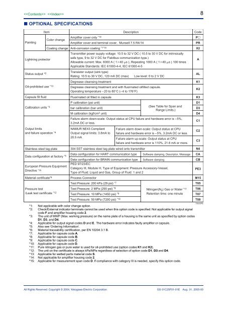
OPTIONAL SPECIFICATIONS<br />
Description<br />
Amplifier cover only *14<br />
Color change<br />
Painting<br />
Amplifier cover and terminal cover, Munsell 7.5 R4/14<br />
Coating change Anti-corrosion coating *1*14<br />
<strong>Transmitter</strong> power supply voltage: 10.5 to 32 V DC ( 10.5 to 30 V DC for intrinsically<br />
safe type, 9 to 32 V DC for Fieldbus communication type.)<br />
Lightning protector<br />
Allowable current: Max. 6000 A ( 140 s ), Repeating 1000 A ( 140 s ) 100 times<br />
Applicable Standards: IEC 61000-4-4, IEC 61000-4-5<br />
Status output * 2<br />
Item<br />
Oil-prohibited use *13<br />
Capsule fill fluid<br />
Calibration units *3<br />
Output limits<br />
and failure operation *4<br />
Stainless steel tag plate<br />
Data configuration at factory *5<br />
European <strong>Pressure</strong> Equipment<br />
<strong>Direct</strong>ive *15<br />
Material certificate *6<br />
<strong>Pressure</strong> test<br />
/Leak test certificate *12<br />
Transistor output (sink type)<br />
Rating: 10.5 to 30 V DC, 120 mA DC (max)<br />
Degrease cleansing treatment<br />
Degrease cleansing treatment and with fluorinated oilfilled capsule.<br />
Operating temperature –20 to 80°C (–4 to 176°F)<br />
Fluorinated oil filled in capsule<br />
P calibration (psi unit)<br />
(See Table for Span and<br />
bar calibration (bar unit)<br />
Range Limits.)<br />
M calibration (kgf/cm 2 unit)<br />
Failure alarm down-scale: Output status at CPU failure and hardware error is –5%,<br />
3.2mA DC or less.<br />
NAMUR NE43 Compliant<br />
Output signal limits: 3.8mA to<br />
20.5 mA<br />
Low level: 0 to 2 V DC<br />
Failure alarm down-scale: Output status at CPU<br />
failure and hardware error is –5%, 3.2mA DC or less.<br />
Failure alarm up-scale: Output status at CPU<br />
failure and hardware error is 110%, 21.6 mA or more.<br />
304 SST stainless steel tag plate wired onto transmitter<br />
Data configuration for HART communication type Software damping, Descriptor, Message<br />
Data configuration for BRAIN communication type Software damping<br />
PED 97/23/EC<br />
Category III, Module H, Type of Equipment: <strong>Pressure</strong> Accessory-Vessel,<br />
Type of Fluid: Liquid and Gas, Group of Fluid: 1 and 2<br />
Process Connector<br />
Test <strong>Pressure</strong>: 200 kPa (29 psi) *7<br />
Test <strong>Pressure</strong>: 2 MPa (290 psi) *8<br />
Nitrogen(N 2 ) Gas or Water *11<br />
Test <strong>Pressure</strong>: 10 MPa (1450 psi) *9<br />
Retention time: one minute<br />
Test <strong>Pressure</strong>: 50 MPa (7200 psi) *10<br />
*1: Not applicable with color change option.<br />
*2: Check/External indicator terminals cannot be used when this option code is specified. Not applicable for output signal<br />
code F and amplifier housing code 2.<br />
*3: The unit of MWP (Max. working pressure) on the name plate of a housing is the same unit as specified by option codes<br />
D1, D3, and D4.<br />
*4: Applicable for output signal codes D and E. The hardware error indicates faulty amplifier or capsule.<br />
*5: Also see ‘Ordering Information’.<br />
*6: Material traceability certification, per EN 10204 3.1 B.<br />
*7: Applicable for capsule code A.<br />
*8: Applicable for capsule code B.<br />
*9: Applicable for capsule code C.<br />
*10: Applicable for capsule code D.<br />
*11: Pure nitrogen gas or pure water is used for oil-prohibited use (option codes K1 and K2).<br />
*12: The unit on the certificate is always kPa/MPa regardless of selection of option code D1, D3 and D4.<br />
*13: Applicable for wetted parts material code S.<br />
*14: Not applicable for amplifier housing code 2.<br />
*15: Applicable for measurement span code D. If compliance with category III is needed, specify this option code.<br />
Code<br />
P<br />
PR<br />
X2<br />
A<br />
AL<br />
K1<br />
K2<br />
K3<br />
D1<br />
D3<br />
D4<br />
C1<br />
C2<br />
C3<br />
N4<br />
CA<br />
CB<br />
PE3<br />
M15<br />
T05<br />
T06<br />
T07<br />
T08<br />
T05.EPS<br />
All Rights Reserved. Copyright © 2004, Yokogawa Electric Corporation<br />
GS 01C25F01-01E Aug. 31, 2005-00