EJX110A Standard Differential Pressure Transmitter - Illawarra ...
EJX110A Standard Differential Pressure Transmitter - Illawarra ...
EJX110A Standard Differential Pressure Transmitter - Illawarra ...
Create successful ePaper yourself
Turn your PDF publications into a flip-book with our unique Google optimized e-Paper software.
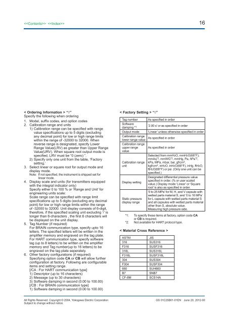
16< Ordering Information > “◊”Specify the following when ordering1. Model, suffix codes, and option codes2. Calibration range and units1) Calibration range can be specified with rangevalue specifications up to 5 digits (excludingany decimal point) for low or high range limitswithin the range of -32000 to 32000. Whenreverse range is designated, specify LowerRange Value(LRV) as greater than Upper RangeValue(URV). When square root output mode isspecified, LRV must be “0 (zero) ”.2) Specify only one unit from the table, ‘Factorysetting.’3. Select linear or square root for output mode anddisplay mode.Note: If not specified, the instrument is shipped set forlinear mode.4. Display scale and units (for transmitters equippedwith the integral indicator only)Specify either 0 to 100 % or ‘Range and Unit’ forengineering units scale:Scale range can be specified with range limitspecifications up to 5 digits (excluding any decimalpoint) for low or high range limits within the rangeof -32000 to 32000. Unit display consists of 6-digit,therefore, if the specified scaling unit excluding ‘/’ islonger than 6-characters , the first 6 characters willbe displayed on the unit display.5. Tag Number (if required)For BRAIN communication type, specify upto 16letters. The specified letters will be written in theamplifier memory and engraved on the tag plate.For HART communication type, specify softwaretag (up to 8 letters) to be written on the amplifiermemory and Tag number(up to 16 letters) to beengraved on the tag plate seperately.6. Other factory configurations (if required)Specifying option code CA or CB will allow furtherconfiguration at factory. Following are configurableitems and setting range.[/CA : For HART communication type]1) Descriptor (up to 16 characters)2) Message (up to 30 characters)3) Software damping in second (0.00 to 100.00)[/CB : For BRAIN communication type]1) Software damping in second (0.00 to 100.00)< Factory Setting > “◊”Tag number As specified in orderSoftwaredamping * 1 ‘2.00 s’ or as specified in orderOutput mode ‘Linear’ unless otherwise specified in orderCalibration rangelower range valueAs specified in orderCalibration rangeupper range As specified in ordervalueCalibration rangeunitDisplay settingStatic pressuredisplay rangeSelected from mmH2O, mmH2O(68°F),mmAq *2 , mmWG *2 , mmHg, Pa, hPa *2 ,kPa, MPa, mbar, bar, gf/cm 2 ,kgf/cm 2 , inH2O, inH2O(68°F), inHg, ftH2O,ftH2O(68°F) or psi. (Only one unit can bespecified.)Designated differential pressure valuespecified in order. (% or user scaledvalue.) Display mode ‘Linear’ or ‘Squareroot’ is also as specified in order.‘0 to 25 MPa’ for M, H, and V capsule withwetted parts material S, and ‘0 to 16 MPa’for L capsule with wetted parts material Sand all capsules with wetted parts materialother than S, absolute value.Measuring high pressure side.*1: To specify these items at factory, option code CAor CB is required.*2: Not available for HART protocol type.< Material Cross Reference >ASTMJIS316 SUS316F316SUSF316316LSUS316LF316LSUSF316L304 SUS304F304SUSF304660 SUH660B7SNB7CF-8MSCS14AAll Rights Reserved. Copyright © 2004, Yokogawa Electric CorporationSubject to change without notice.GS 01C25B01-01ENJune 20, 2012-00


