STM and AFM Tutorial
STM and AFM Tutorial
STM and AFM Tutorial

Create successful ePaper yourself
Turn your PDF publications into a flip-book with our unique Google optimized e-Paper software.
<strong>STM</strong> <strong>and</strong> <strong>AFM</strong> <strong>Tutorial</strong>Katie MitchellJanuary 20, 2010
Overview• Scanning Probe Microscopes• Scanning Tunneling Microscopy (<strong>STM</strong>)• Atomic Force Microscopy (<strong>AFM</strong>)– Contact <strong>AFM</strong>– Non-contact <strong>AFM</strong>• RHK UHV350 <strong>AFM</strong>/<strong>STM</strong>
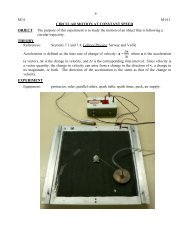
Scanning Probe MicroscopesScanning tunneling microscope• Sharp probe tip is scannedacross surface• Piezoelectric materialsprovide atomic scalecontrol of x,y,z motion• Detect signal that reflectstopography or otherspatially varying propertyof interest• Good vibration isolationrequired
Scanning Tunneling Microscopy• V ~ 0.1 - 2 V• I ~ pA – nAImage from Will's Nanotechnology Blog• can operate inair, liquid orvacuum• sample <strong>and</strong> tipmust beconducting
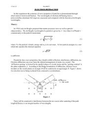
E FE FScanning Tunneling MicroscopyTip1D Potential Barriera)Sample0 2 exp w n2zeVe -TipSample Tipb)c)E Fe - 2m E FE FE Fz 2SampleeV
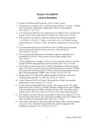
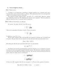
Natural Log of Tunneling CurrentCurrent-Distance Dependence10W <strong>and</strong> Pt-Ir tips onSi(111)-7x7-1-2-3 = 1.0±0.1 Å -1-4-5-6-70.0 0.5 1.0 1.5 2.0 2.5 3.0Tip Displacement (Å)M. Rempel, MSc Thesis, Univ. of Saskatchewan, 2003
Scanning Tunneling Microscopy3D Picturew2M2 EETransition probabilityI4eeV02E eV EMdFFTunneling currentI4eeV0E eV E dFFAssuming s-wave tip state
<strong>STM</strong> on Au(111)120°60°100 x 100 nm, 25 mV, 1.15 nA
Au(111): High Resolution50 x 50 nm, 25 mV, 1.15 nA5 x 5 nm, 90 mV, 1.09 nA
Highly Ordered Pyrolytic Graphite(HOPG)5 nm x 5 nm<strong>STM</strong> image0.1V, 1.0 nAPt-Ir tipImages,Mark RempelHOPG lattice
Si(111) – 7x7-1.5 V, 0.42 nA - filled statesModel of Si(111)-7x7surface structure; the sidelength of the surface unitcell is 26.6 Å+1.5 V, 0.50 nA - empty states<strong>STM</strong> images, Dale Heggie
Si(111) – 7x7+1.5 V, 0.12 nA +1.5 V, 0.78 nA +1.5 V, 0.80 nA+2.0 V, 0.34 nA <strong>STM</strong> images, Dale Heggie
InP(100)-1.81 V, 0.35 nA -2.0 V, 0.23 nA<strong>STM</strong> images, Dale Heggie
InP(100)“ghost” tip imagesnoise-1.8 V, 0.58 nA
Scanning Tunneling Spectroscopy• Measure I(V)• Calculate sample density of statesdIdVIV E eV F
Si(111)-7x7• (dI/dV)/(I/V) as a function ofsample bias, for Si(111)-7x7• (a) – (d) W tip• (e) – (f) Pt-Ir tip• features can be comparedto expected density of statesfor Si(111)-7x7 surfaceFigure, Mark Rempel
<strong>STM</strong> Tips• Most common tips– Electrochemically etched W wire– Mechanically cut Pt-Ir wire• Desirable properties– Conducting– Hard– Inert (for imaging in air)– Best shape varies with application
SEM imagesTungsten <strong>STM</strong> tip imaged at 150x <strong>and</strong> 20,000x magnificationa) b)100 m 1 m
DC Drop-off Method for Tungsten• Anode (W wire) <strong>and</strong> cathodesubmerged in aqueoussolution of NaOH or KOH• W wire etches <strong>and</strong> breaks atthe air/solution interface• Remaining wire is used as thetipC.J. Chen, Introduction to Scanning Tunneling Microscopy. OUP (1993)19
Etching MechanismAnodeW(s) + 6OH - WO 3 (s) + 6e - + 3H 2 OWO 3 (s) + 2OH - WO2-4 (aq) + H 2 OCathode6H 2 O + 6e - 3H 2 (g) + 6OH -OverallW(s) + 2OH - + 2H 2 O 3H 2 (g) +WO 42-(aq)G. Stephen Kelsey, J. Electrochem. Soc. 124(6), 814(1977).20
Etching Apparatus21
Atomic Force Microscopy• measure deflection ofa cantilever of knownspring constant, due totip-surface interactionforces• F ~ nN• can operate in air,liquid or vacuumImage from Will's Nanotechnology Blog• sample <strong>and</strong> tip may beconducting or insulating
Atomic Force MicroscopyWikipedia• Contact Mode– Operate in region of repulsive tip-sample forces– Scanning at constant cantilever deflection results in contour mapof constant force, which represents topography– Twisting of cantilever is a measure of lateral (friction) forces– Contact mode can be very useful but can also be damaging todelicate surfaces
Atomic Force MicroscopyWikipedia• Non-Contact Mode (NC <strong>AFM</strong>)– Operates in region of attractive (van der Waals) forces– Cantilever is forced to oscillate at its resonant frequency (100-300 kHz)– Change in force experienced by tip changes the resonant frequency– Change in resonant frequency is used as the feedback signal– Very high Q cantilevers allow very small changes in resonant frequencyto be detected, <strong>and</strong> thus small changes in force– Ideal for delicate samples, <strong>and</strong> can give atomic resolution
Force-Distance CurvesShahin, V. et al. J Cell Sci 2005;118:2881-2889
<strong>AFM</strong> Cantilevers <strong>and</strong> TipsSEM image of cantilever• Microfabricated cantilevers with integrated tips– Silicon nitride, silicon oxide, silicon– Spring constants: 0.1-1 N/m (contact), 10-100 N/m (non-contact)– Resonance frequencies: 1-50 kHz (contact), 100-300 kHz (non-contact)– Coatings depend on application: eg. conducting, magnetic,functionalized (specific molecules)
Cantilever Example• Nanosensors PPP-NCL-10– Intended for non-contact mode– Fabricated from n-type silicon– no coating– Specifications• t = 7.00 microns• w = 38 microns• l = 229 microns• h = 10 – 15 microns• c = 47 N/m• f = 184 kHz• Tip radius ~ 7 nm
RHK UHV 350 <strong>AFM</strong>/<strong>STM</strong>• full range of <strong>AFM</strong> acquisition modes• <strong>AFM</strong>, <strong>STM</strong> or simultaneous<strong>AFM</strong>/<strong>STM</strong>Position sensitivedetectorRHK Technology Inc.CantileverSample holder
Design Features• Sample stationary, tip/cantilever scanned• “Beetle” or “Walker” design– Piezo legs walk down ramp due to slip/stick• Piezo legs used for approach <strong>and</strong> scanning• Central piezo stack used for z motion• Laser deflection <strong>and</strong> 4-quadrant PSD<strong>AFM</strong>, Wikibooks
Design Features• Head accepts <strong>STM</strong> tip or <strong>AFM</strong> cantilever holders• Tip <strong>and</strong> cantilever holders can be transferred on <strong>and</strong> off invacuum• Sample may be heated or cooled while scanning• Vibration isolation– External airlegs– Viton stack supporting sample stage– Scan head designed to have high resonant frequencies– Scan head decoupled from chamber
Sample HoldersSapphire washer to hold sample in placeThermocouple connectionsRamps for piezo legs
• SPM 1000 controller– Primary interfaceControl Hardware– Front-panel controls• PLL Pro– Digital controller for <strong>AFM</strong>• PMC 100 Piezo Motor Control– Controls laser lens <strong>and</strong> position sensitive detectormotors for <strong>AFM</strong>• Small piezo control box (for X,Y,Z)
• XPMProControl Software– <strong>STM</strong>/<strong>AFM</strong> data acquisition, processing <strong>and</strong> analysis– May be used free for data analysis on any computerrunning Windows (XP, Vista)*• PLLPro– Controls the <strong>AFM</strong> mode, <strong>and</strong> all setup <strong>and</strong>parameters for <strong>AFM</strong> operation*http://www.rhk-tech.com/downloads_files_V2.php
SpecificationsFrom RHKproduct brochure