6 M14 M14.1 CIRCULAR MOTION AT CONSTANT SPEED OBJECT ...
6 M14 M14.1 CIRCULAR MOTION AT CONSTANT SPEED OBJECT ...
6 M14 M14.1 CIRCULAR MOTION AT CONSTANT SPEED OBJECT ...
- No tags were found...

You also want an ePaper? Increase the reach of your titles
YUMPU automatically turns print PDFs into web optimized ePapers that Google loves.
6<strong>M14</strong> <strong>M14</strong>.1<strong>CIRCULAR</strong> <strong>MOTION</strong> <strong>AT</strong> <strong>CONSTANT</strong> <strong>SPEED</strong><strong>OBJECT</strong> The purpose of this experiment is to study the motion of an object that is following acircular trajectory.THEORYReferences: Sections 7.1 and 7.4, College Physics, Serway and VuillevAcceleration is defined as the time rate of change of velocity: a = where a is the accelerationt(a vector), v is the change in velocity, and t is the corresponding time interval. Since velocity isa vector quantity, the change in velocity can arise from a change in the direction of v, a change inits magnitude, or both. The direction of the acceleration is the same as that of the change invelocity.EXPERIMENTEquipment: protractor, ruler, parallel rulers, spark table, spark timer, puck, air supply:
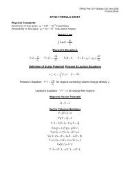
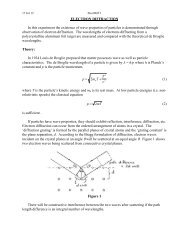
7<strong>M14</strong>.2Figure 1The spark timer produces High Voltage electrical pulses. Do not touch thespark table, puck, or wire when the spark timer is in operation. Follow the labdemonstrator’s instructions.The apparatus, shown in the photograph and Figure 1, consists of an aluminum plate over which asheet of sensitized carbon paper is placed with a sheet of white paper above it. A metal puckwhich can be supported on an air cushion in an almost frictionless state is anchored with a piece ofwire to the centre of the plate. A spark timer, connected between the plate and the centre of thepuck, delivers a pulse at regular intervals. The spark jumps from a pin located in the centre of thepuck to the plate and in so-doing deposits a dot of carbon onto the white paper, thus recording theposition of the puck as a function of time. The spark timer frequency is 10 Hz ± 1%, i.e. there are10 dots/second, so the time between each successive dot is 0.100 s.Procedure:Level the apparatus.Without using the spark timer, turn on the air and practise projecting the puck into a smoothcircular trajectory. The puck should take approximately 2 seconds for one revolution.Turn on the air, project the puck into a smooth circular trajectory, and make a spark trace of itspath. Avoid overlapping the trace. Before removing the paper, mark the approximate start point ofthe spark trace and the direction of motion of the puck. If an appropriate puck speed was used,successive dots on the trace should be spaced at ~6 to ~8 cm intervals. To perform the analysisdiscussed below, your trace must have at least 17 dots (numbered from 0 to 16), and should nothave more than 21 dots.ANALYSISMeasure the radius r of the circular trajectory by measuring the distance from the centre to one ofthe spark dots.Consider the portion of a typical spark trace shown in Figure 2.
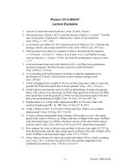
8<strong>M14</strong>.3s 1 (arc 0-2)1v 12v 3 – v 1(translated)s 3 (arc 2-4)34v 30v 3 – v 1–v 156 1 3Figure 2Recall that the direction of the instantaneous velocity at any location is tangent to the trajectory.The magnitude of the instantaneous velocity at a location can be approximated by determining theaverage speed over a small time interval around the location.Recall the equation for converting angles in degrees into angles in radians:2360and the equation for arclength (obtained from the definition of radian angle measure):s = r rad (2)For example, the magnitude of the velocity at point 1 is given byradrad o o(1)s1v 1 (3)twhere s 1 is the arclength travelled during the time interval t 1 (= 0.200 s). Note that s 1 = r 1where r is the radius of the trajectory and 1 is the angle through which the radius sweeps as theobject moves from point 0 to point 2.Use a protractor to measure the angles 1 , 3 , 7 , 9 , 13 , and 15 .Calculate the magnitudes of the velocities at points 1, 3, 7, 9, 13, and 15.Choose an appropriate scale and draw the velocity vectors at points 1, 3, 7, 9, 13, and 15 on thespark trace. (Note that if the speed is constant, then the tangent to the circle at point 1 will beparallel to the chord between ponts 0 and 2. This may help with ensuring that the velocity vectors1
9<strong>M14</strong>.4are drawn in the correct directions. Alternatively, use a straightedge and large triangle to constructthe tangents.)The average acceleration, a 2 , over the time interval t 2 (= 0.200 s) is defined asvv v1 3 3 1a2(4)t2t2where v 3 – v 1 is the vector that results from the vector subtraction of vectors v 3 and v 1 (see nextparagraph).Use the parallel rulers to construct the resultant of the vector subtraction v 3 – v 1 . Use the parallelrulers to translate the resultant so that it acts at point 2. Note that from equation (4) the direction ofthis resultant is also the direction of the acceleration a 2 . Measure the length of the resultant vectorand, using your velocity-to-length scale and equation (4), calculate the magnitude of theacceleration a 2 .Using the graphical vector subtraction method discussed above, also determine the accelerationsa 8 and a 14 . Calculate the average and average deviation (see p. xvi) of your acceleration values.CONCLUSIONIn what direction do the acceleration vectors point?Can anything be concluded regarding the magnitudes of the acceleration vectors?Is there a force acting on the puck while it is in circular motion, and if so, what is the origin of thisforce?In your own words, describe what you have determined, from this experiment, regarding themotion of an object that is following a circular trajectory.SOURCES OF ERRORIn addition to discussing any factors that likely affected the experiment, answer the followingquestion(s): was the puck moving with constant speed and, if not, what factors could have affectedits speed?
10<strong>M14</strong><strong>CIRCULAR</strong> <strong>MOTION</strong> <strong>AT</strong> <strong>CONSTANT</strong> <strong>SPEED</strong>D<strong>AT</strong>A & RESULTSPeriod of timer:___________________________________________Radius of circular trajectory: r = ________________ ± ________________ cmPointsonsparktraceAngle(± ____ )Angle(± ____ rad)(eq’n (1))Arclengths(cm)(eq’n (2))Magnitude ofVelocity, v(cm/s)(eq’n (3))Magnitude ofvectorsubtractionof velocities(cm/s)Magnitude ofAverageAcceleration(cm/s 2 )(eq’n (4))0-2 ± ±2-4 ± ±6-8 ± ±8-10 ± ±12-14 ± ±14-16 ± ±AverageAve. Dev.(= error inavg.)