
Create successful ePaper yourself
Turn your PDF publications into a flip-book with our unique Google optimized e-Paper software.
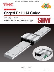
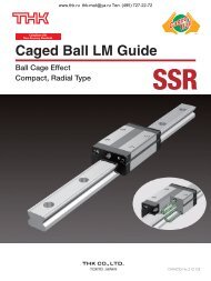
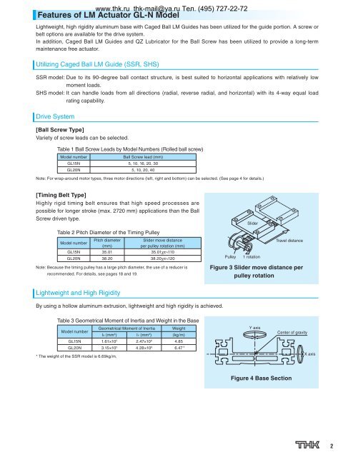
Features of <strong>LM</strong> <strong>Actuator</strong> <strong>GL</strong>-N ModelLightweight, high rigidity aluminum base with Caged Ball <strong>LM</strong> Guides has been utilized for the guide portion. A screw orbelt options are available for the drive system.In addition, Caged Ball <strong>LM</strong> Guides and QZ Lubricator for the Ball Screw has been utilized to provide a long-termmaintenance free actuator.Utilizing Caged Ball <strong>LM</strong> Guide (SSR, SHS)SSR model: Due to its 90-degree ball contact structure, is best suited to horizontal applications with relatively lowmoment loads.SHS model: It can handle loads from all directions (radial, reverse radial, and horizontal) with its 4-way equal loadrating capability.Drive System[Ball Screw Type]Variety of screw leads can be selected.www.thk.ru thk-mail@ya.ru Тел. (495) 727-22-72Table 1 Ball Screw Leads by Model Numbers (Rolled ball screw)Model numberBall Screw lead (mm)<strong>GL</strong>15N 5, 10, 16, 20, 30<strong>GL</strong>20N 5, 10, 20, 40Note: For wrap-around motor types, three motor directions (left, right and bottom) can be selected. (See page 4 for details.)[Timing Belt Type]Highly rigid timing belt ensures that high speed processes arepossible for longer stroke (max. 2720 mm) applications than the BallScrew driven type.Table 2 Pitch Diameter of the Timing PulleyModel numberPitch diameter(mm)Slider move distanceper pulley rotation (mm)<strong>GL</strong>15N 35.01 35.01χπ 110<strong>GL</strong>20N 38.20 38.20χπ 120Note: Because the timing pulley has a large pitch diameter, the use of a reducer isrecommended. For details, see pages 18 and 19.PulleySlider1 rotationTravel distanceFigure 3 Slider move distance perpulley rotationLightweight and High RigidityBy using a hollow aluminum extrusion, lightweight and high rigidity is achieved.Table 3 Geometrical Moment of Inertia and Weight in the BaseModel numberGeometrical Moment of Inertia WeightlX (mm 4 ) lY (mm 4 ) (kg/m)<strong>GL</strong>15N 1.61×10 5 2.47×10 6 4.85<strong>GL</strong>20N 3.15×10 5 4.28×10 6 6.47 ** The weight of the SSR model is 6.69kg/m.Y axisCenter of gravityX axisFigure 4 Base Section