Loop Amplifier LA210 Instructions - Sarabec
Loop Amplifier LA210 Instructions - Sarabec
Loop Amplifier LA210 Instructions - Sarabec
- No tags were found...

Create successful ePaper yourself
Turn your PDF publications into a flip-book with our unique Google optimized e-Paper software.
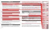
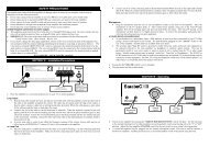
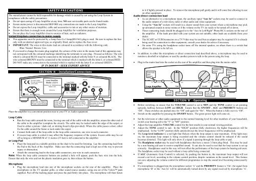
SAFETY PRECAUTIONSThe manufacturer cannot be held responsible for damage which is caused by not using the <strong>Loop</strong> System incompliance with the safety precautions.• Do not open casing of <strong>Loop</strong> <strong>Amplifier</strong> at any time; NO user serviceable parts can be found inside.• Ensure mains power is disconnected BEFORE any connections are made to the <strong>Loop</strong> <strong>Amplifier</strong>.• Do not expose the <strong>Loop</strong> <strong>Amplifier</strong>, cable and accessories to rain or any other source of moisture.• Ensure that there is enough room around the <strong>Loop</strong> <strong>Amplifier</strong> for ventilation purposes.• Do not place the <strong>Loop</strong> <strong>Amplifier</strong> close to sources of heat, such as radiators.United Kingdom connection to mains supply• This apparatus must be protected by a 3amp fuse if a 13amp(BS1363) plug is used. Be sure to replace the fuseonly with an identical approved type, as originally fitted, and to replace the fuse cover.• IMPORTANT: The wires in this mains lead are coloured in accordance with the following codeBlue: Neutral Brown: Live.• If you need to change the mains plug supplied, the colours of the wires in the mains lead of this apparatus maynot correspond with the coloured markings identifying the terminals in your plug. Proceed as follows: The wirewhich is coloured BLUE must be connected to the terminal marked with the letter N or coloured BLACK. Thewire coloured BROWN must be connected to the terminal which is marked with the letter L or coloured RED.DO NOT make any connection to the terminal which is marked with the letter E or coloured GREEN.IF IN DOUBT - SEEK EXPERT ADVICEESECTION ‘A’ - Installation/Connectionsto it if lightly pressed in place. To remove the microphone pull gently and it will come free allowing its useon other equipment.Audio direct connection lead• As an alternative to a microphone input, the auxiliary input “Aux In” sockets may be used to connect tothe audio outputs of a television, radio or other audio and video equipment.• Using the “Aux In” sockets will result in a clearer sound from your system where a microphone may pickup unwanted sounds in noisy rooms or if the volume on the TV etc needs to be turned off or down.• These connecting leads should be plugged in to the “Aux In Left/Right” Phono/RCA sockets on the rear ofthe amplifier. If the leads provided with your system are not suitable, other leads are available from yourdealer.• The SCART or EUROconnector on a TV/Video may be used but an adaptor may be required if it is alreadybeing used for connection to other equipment, consult your dealer for advice if necessary• On some TVs using the headphone socket turns off the internal speaker, on others there is a switch thatallows the speaker to be left on.• In addition, to either the microphone or direct connection lead described above, a microphone may be used tomonitor a doorbell or telephone or used by another person to talk to the person using the loop.• Plug in the mains lead into the socket on the rear of the amplifier and then plug into the mains outlet.AutomaticGainControlHeadphonesocketPower"ON/OFF"switchDO NOT OPENNo user serviceableparts inside.<strong>Loop</strong> <strong>Amplifier</strong>Model: <strong>LA210</strong><strong>Sarabec</strong> Ltd., MiddlesbroughMade in UK<strong>Loop</strong> CableLeftAux InMicrophonesAGCPRIORITY<strong>Loop</strong> <strong>Amplifier</strong>LOW HIGHMIN MAXTONEVOLUMEPHONESON/OFF230V~ 50Hz 20 VA MaxSerial No:0.5 - 1.5 OhmsRightABPriorityControlTone ControlVolume Control<strong>Loop</strong> levelindicatorONlight230 Volt AC MainsPower Lead Socket<strong>Loop</strong> Cable or<strong>Loop</strong> PadconnectorsAuxiliary input sockets(Phono/RCA) for directlead connections to TV orHiFi etc.Place the amplifier in a convenient position near to your TV or Audio equipment.Microphone inputsockets (3.5mmmono jack)<strong>Loop</strong> Cable• Run the loop cable around the room, leaving one end of the cable with the amplifier, return the other end ofthe cable to the amplifier (complete the circuit). The cable may be tucked under the edge of the carpet, orfixed to either a picture / dado rail, or skirting board (clips provided). Where the cable passes a door, eitherfix the cable around the frame or tuck under the carpet.• Connect both ends of the loop cable to the loop cable connectors, one wire in each connector.• If excess loop cable is coiled it may affect the frequency response of the system. Excess cable may be cutoff as long as a MINIMUM of 11 metres (35 feet) is left connected to the amplifier.or <strong>Loop</strong> Pad• Place the loop pad in a suitable position on the chair to be used for listening. Lay the connecting lead fromthe Pad to the back of the <strong>Amplifier</strong>. Make sure that the connecting lead is kept out of the way to preventinjury or obstruction.• Attach the connecting lead to the loop cable connectors, one wire in each connector.Note: When the loop cable connector buttons are pushed a hole will appear, push the bare wire into the hole.Ensure that only the wire and not the plastic insulation goes in, then release the button.Microphone• Plug the microphone lead into one of the microphone sockets on the rear of the amplifier. Place themicrophone on the TV speaker grille, or other sound source speaker, using one set of the Velcro padssupplied. Peel off the backing paper and press the pad firmly into place. The microphone will then fastenSECTION ‘B’ - Operating• Before switching on ensure that the VOLUME control is set to MIN and the TONE control is set pointingupwards, halfway between LOW and HIGH. Ensure that the ON/OFF , AGC and PRIORITY buttons are‘Off’. These switches are pushed once for ‘Off’ and again for “On”. When the button is fully out it is ‘Off’.• Switch on the amplifier by pressing the ON/OFF button. The green power light will come on.• Set the television or other audio equipment to the normal listening level for other members of your household,switch your hearing aid to the “T” or “MT” position.• Adjust the loop amplifier VOLUME control for the best results in your normal viewing position.• Adjust the TONE control to suit. In the “HIGH” position (fully clockwise), the higher frequencies will beemphasised. In the “LOW” position (fully anticlockwise) the lower frequencies will be emphasised.• The <strong>Loop</strong> level indicator is a red light that flickers when the loop output is near maximum. If the light stayson, the maximum loop output is being exceeded and the volume control should be reduced if the soundbecomes distorted. This light will only show if a signal is passing through the loop cable or pad.• The Headphone socket may be used with headphones that have a stereo 3.5mm plug fitted. This may be usedby a non hearing aid user to receive amplified sound. It can also be used to test that the loop system is set upcorrectly. Headphones used in this way will not affect the performance of the loop system for hearing aid users.The headphone socket may be used without a loop cable being connected.• If AGC (Automatic Gain Control) is selected, by pushing the button in, the maximum loop output will notexceed a set level, according to the volume control position, despite variations in the sound level. This featurecan save adjusting the volume control for different programmes to stop the sound level becoming unnecessarilyloud.• If a microphone is plugged into the microphone socket ‘A’ and the PRIORITY feature is ‘On’, the signal frommicrophone ‘B’ or the ‘Aux In’ will be automatically turned down by any signal received by microphone ‘A’.
This feature useful where a microphone is used to monitor a doorbell or telephone bell or with a second personspeaking.• The priority feature should be switched ‘Off’ if microphone ‘A’ if it is located in a noisy place, otherwise thepriority feature will keep the wanted sound in channel ‘B’ reduced.SECTION ‘C’ - Problems and CuresSymptomPossible cause and remedyNo sound. • Re-check all connections. Check diagrams.• <strong>Amplifier</strong> not switched on. Switch on at mains socket. Press mains switch.Check green LED light is on.• Microphone not plugged in or other audio source not connected.• Hearing aid not on “T/MT” or “T” facility not working.Low sound. • Microphone too far from sound.• <strong>Loop</strong> cable wired incorrectly. Check diagrams.• Volume control set too low. Turn up volume on amplifier.• Radio or TV volume set too low. Turn up volume on Radio or TV.Distorted sound • <strong>Loop</strong> Volume control too high. (level indicator light on) Turn volume down.• Radio or TV volume set too high. Turn down volume on Radio or TV.• Move microphone away from loud speaker.• Microphone plug/lead damaged.Background noise(hum or buzz)• If noise remains when loop amplifier is turned off but hearing aid is still on“T”, this is interference caused by other equipment such as TV, fluorescentlights or dimmer switches. With the loop amplifier turned off and the hearingaid still on “T” turn items off in turn until the noise goes away.• If noise stops when the loop amplifier is turned off there may be a fault in thesystem or microphone lead or noise is being picked up by the microphone.If in doubt please contact your dealer for assistance.SECTION ‘D’ - SpecificationPower Supply • 230 V AC 20VA Max via Fig 8 mains lead.Controls • Rotary VOLUME control to vary the output level.• Rotary TONE control to vary the output tone.• ON/OFF power push button switch.• AGC and PRIORITY function push button switches.Input connections • 2 microphone inputs A/B. 3.5mm mono jack plug. DC powered for electretmicrophones.• Aux In Left/Right line input. Phono/RCA sockets. For direct connection to aTV sound output or other audio source via SCART or other suitable socket.Output connections • Push grip connectors for loop cable or loop pad (Labelled: <strong>Loop</strong> Cable). <strong>Loop</strong>will give full output with loop resistance between 0.5 and 1.5 Ohms.Headphone output • 3.5mm stereo jack for headphones (Phones) 8-60 Ohms.<strong>Loop</strong> output • 2.85A output current @ 100-5kHz. Sufficient to meet BS6083 pt4 (IEC118-4)in a loop not exceeding 6.25m(20ft) in width for most domestic situations.<strong>Loop</strong> cable • Single turn loop cable. Standard system supplied with 37m(120ft) 24/0.2(0.75mm²) single core PVC insulated cable and cable clips. Minimum cablelength 11m = 0.5 Ohms.Indicators • Green Light Emitting Diode (LED) for Power On indication.• Red Light Emitting Diode (LED) <strong>Loop</strong> Level IndicatorProduct conforms to the provisions of the following European Union Directives :• 73/23 Low Voltage Directive• 89/336 & 92/31 Electro Magnetic Compatibility DirectivesHome <strong>Loop</strong> System/<strong>Loop</strong> Pad SystemModel <strong>LA210</strong>IntroductionOwner’s ManualThe <strong>Sarabec</strong> <strong>LA210</strong> Home <strong>Loop</strong> System provides a practical solution for hearing aid users tolisten more easily to their TV or Audio equipment via the “T” or “MT” facility of their aid.With no direct connection between the user and the TV the user is able to move freely withinthe looped area and listen comfortably to the TV or other equipment.The Home <strong>Loop</strong> System is used in conjunction with a hearing aid with a switch positionmarked "T" or "MT", this is found on most 'behind the ear' hearing aids. The system picks upthe sound from the TV via a microphone and feeds it to the amplifier. The amplifier passesthe sound to a loop of wire around the listening area, which in turn transmits the soundinductively, “magnetic sound waves”, to the hearing aid. The user may then adjust the loopvolume to suit their own hearing preference without affecting other people.The Home <strong>Loop</strong> System is supplied with <strong>Loop</strong> Cable to be placed around a room that youwant to listen in. The <strong>Loop</strong> Pad System is an alternative to the standard Home <strong>Loop</strong> Systemcreating either a portable loop system or a localised system where adjacent loop systemscould interfere with each other.The Home <strong>Loop</strong> System is supplied ready for use with the following items.1. <strong>LA210</strong> <strong>Loop</strong> <strong>Amplifier</strong>.2. Mains lead with fitted plug.3. 2 Microphones with Velcro pads4. SCART to Phono direct connection lead5. 37m(120ft) <strong>Loop</strong> Cable and pack of 50 cable clipsor<strong>Loop</strong> Pad with 5m(15ft) connecting cable6. Guarantee Card7. Owners manual<strong>Sarabec</strong> Limited 15 High Force Road Middlesbrough TS2 1RH UKTelephone (01642) 247789 Fax (01642) 230827 Text (01642) 251310®is a mark of <strong>Sarabec</strong> Ltd.© <strong>Sarabec</strong> Ltd 135-x1x.002 0304 <strong>LA210</strong>.doc