LT1 Loop Amplifier Instructions - Sarabec
LT1 Loop Amplifier Instructions - Sarabec
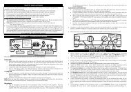
LT1 Loop Amplifier Instructions - Sarabec

Create successful ePaper yourself
Turn your PDF publications into a flip-book with our unique Google optimized e-Paper software.
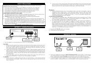
Description.This Home <strong>Loop</strong> System enables you to listen more easily, with no direct connection, to the TV orother sound source. It is used in conjunction with a hearing aid with a switch position marked "T" or"MT", this is found on most 'behind the ear' hearing aids. The system picks up the sound from the TVvia a microphone and feeds it to the amplifier. The amplifier passes the sound to a loop of wire aroundthe listening area, which in turn transmits the sound inductively to the hearing aid. You may adjust thevolume to your own level without affecting other people.The loop system is supplied ready for use with a fitted mains plug, a miniature microphone, "Velcro"pads, loop cable and a packet of cable clips.<strong>Instructions</strong> for use.1. Place the amplifier in a convenient position near to the television. Place the loop cable around theroom. Leave one end of the cable at the amplifier and lay the cable around the edge of the room.Make a complete circuit back to the amplifier. The cable may be tucked under the edge of a carpet, orfixed to the skirting board or picture rail. At doors either fix the cable around the door frame or tuck itunder the carpet.2. Connect the cable to the back of the amplifier (see following diagram).Connect one end of the cable to the left hand pair of terminals. When the terminal is pushed a hole willappear, push the wire into the hole, making sure that only the wire and not the plastic insulation goesin, then release the terminal. Ensure the wire marked black goes to the black terminal and the wiremarked red goes to the red terminal. Similarly, connect the other end of the cable to the right hand pairof terminals, black to black and red to red. If excess cable is coiled up it may affect the frequencyresponse of the system. Excess loop cable can be cut off as long as a MINIMUM length of 35 feet (11metres) is left connected to the amplifier. Longer cables are available, if required, up to a maximum of120 feet (37 metres).3. Plug the microphone lead into the Microphone socket marked "A" on the front panel. Place themicrophone on the television speaker grille, using one of the "Velcro" pads supplied. Peel off thebacking paper and press the pad firmly into place. The "Velcro" already on the microphone will thenfasten to it if pressed lightly into place. To remove the microphone pull gently and it will come freeallowing its use on other equipment.4. Plug the amplifier into the mains and switch on at the socket, then switch on the amplifier bypressing the green rocker switch, which will glow. Make sure that the two round switches to the left ofthe green on/off switch are in the off position. Set the television to the normal listening level for theother members of your household, switch your hearing aid to the "T" or "MT" position. Adjust theloop amplifier volume control for the best results in your normal viewing position.5. Tone Control. The amplifier is fitted with a variable tone control to the right of the Volumecontrol. In the «_High»_ position the amplifier will emphasise the higher frequency range and in the«_Low»_ position the lower frequency range will be emphasised. In the «_Normal»_ position the highand low frequency ranges are NOT emphasised.7. Priority control PRI. If a second microphone is plugged into microphone socket marked B thiscan be made to override the signal coming from the microphone in the A socket or the auxiliary input.When the PRI switch is in the "on" position the volume of the A microphone will be turned down whenthe B microphone picks up a sound above a threshold level. This can be useful if a second microphoneis used to monitor a doorbell or telephone bell, or another person wants to talk to someone whilst theyare using the loop. However if a second microphone is used in a noisy room or the TV is turned uploudly this feature should be turned off. When the switch is in the "off" position there is no override ofMicrophone "A" by Microphone "B".SWITCH OFF THE AMPLIFIER WHEN NOT IN USE.Further InformationAn auxiliary input socket is provided on the rear of the amplifier. This enables television, radio, audioand video equipment to be connected directly to the loop amplifier via headphone or auxiliary outputsockets. This can be particularly useful in very noisy rooms or when no sound at all is wanted from theTV or a direct connection to a stereo TV or sound system is required. This socket is wired for signal inon pins 3 & 5 and ground on pin 2. This socket is connected to the same input channel as microphoneA and can be overridden by microphone B if the priority feature is switched on. To make use of theinput socket the equipment to be connected must have a suitable OUTPUT socket. These may bedescribed in different ways and were originally intended for various purposes. They may be markedAudio out, Tape out, or Headphones. The SCART or EUROSOCKET on modern TVs can be used butan adaptor may be required if it is already being used for connection to other equipment. On some TVsusing the headphone socket turns off the TV speaker, on others there is a switch that allows the speakerto be left on if required.Fault FindingIf a loop system was working normally the last time it was used and then fails to work then suspectdamage to the loop cable, including connections, or microphone lead. When re-arranging furniture orspring cleaning care needs to be taken not to damage these parts.WARNING: THIS APPARATUS MUST BE EARTHEDIMPORTANT: The wires in the mains lead on this amplifier are coloured in accordance with thefollowing code GREEN/YELLOW=EARTH BLUE=NEUTRAL BROWN=LIVE.If you need to change the plug already fitted to this appliance these colours may not correspond withthe markings identifying the terminals in your plug. If this is so proceed as follows: The wire which iscoloured GREEN/YELLOW must be connected to the terminal marked with the letter E, by the earthsymbol or coloured GREEN.The wire which is coloured BLUE must be connected to the terminal marked with the letter N orcoloured BLACK. The wire which is coloured BROWN must be connected to the terminal which ismarked with the letter L or coloured RED. This apparatus must be protected by a 3amp fuse if a13amp(BS1363) plug is used. There are no user adjustable or replaceable parts inside the amplifier andat no time should the user take the equipment apart.6. Automatic Gain Control AGC. The switch marked AGC operates the automatic gain control,when this is switched on the output signal from the loop will remain almost constant despite variationsin the sound level picked up by the microphone. This feature can save adjusting the volume control fordifferent programmes.
724-040 1094Home <strong>Loop</strong> SystemModel <strong>LT1</strong><strong>Sarabec</strong> Limited 15 High Force Road Middlesbrough Cleveland TS2 1RHTelephone (01642) 247789 Fax (01642) 230827 Text (01642) 251310