Britflex BEJ Expansion Joints - StonCor Africa
Britflex BEJ Expansion Joints - StonCor Africa
Britflex BEJ Expansion Joints - StonCor Africa
- No tags were found...

Create successful ePaper yourself
Turn your PDF publications into a flip-book with our unique Google optimized e-Paper software.
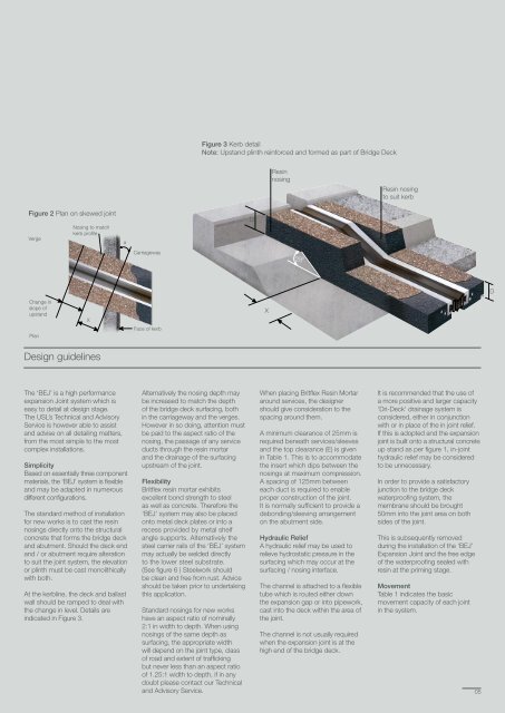
Figure 3 Kerb detailNote: Upstand plinth reinforced and formed as part of Bridge DeckResinnosingResin nosingto suit kerbFigure 2 Plan on skewed jointVergeNosing to matchkerb profileaDCarriageway25ºDChange inslope ofupstandXXPlanFace of kerbDesign guidelinesThe ‘<strong>BEJ</strong>’ is a high performanceexpansion Joint system which iseasy to detail at design stage.The USL’s Technical and AdvisoryService is however able to assistand advise on all detailing matters,from the most simple to the mostcomplex installations.SimplicityBased on essentially three componentmaterials, the ‘<strong>BEJ</strong>’ system is flexibleand may be adapted in numerousdifferent configurations.The standard method of installationfor new works is to cast the resinnosings directly onto the structuralconcrete that forms the bridge deckand abutment. Should the deck endand / or abutment require alterationto suit the joint system, the elevationor plinth must be cast monolithicallywith both.At the kerbline, the deck and ballastwall should be ramped to deal withthe change in level. Details areindicated in Figure 3.Alternatively the nosing depth maybe increased to match the depthof the bridge deck surfacing, bothin the carriageway and the verges.However in so doing, attention mustbe paid to the aspect ratio of thenosing, the passage of any serviceducts through the resin mortarand the drainage of the surfacingupstream of the joint.Flexibility<strong>Britflex</strong> resin mortar exhibitsexcellent bond strength to steelas well as concrete. Therefore the‘<strong>BEJ</strong>’ system may also be placedonto metal deck plates or into arecess provided by metal shelfangle supports. Alternatively thesteel carrier rails of the ‘<strong>BEJ</strong>’ systemmay actually be welded directlyto the lower steel substrate.(See figure 6 ) Steelwork shouldbe clean and free from rust. Adviceshould be taken prior to undertakingthis application.Standard nosings for new workshave an aspect ratio of nominally2:1 in width to depth. When usingnosings of the same depth assurfacing, the appropriate widthwill depend on the joint type, classof road and extent of traffickingbut never less than an aspect ratioof 1.25:1 width to depth, if in anydoubt please contact our Technicaland Advisory Service.When placing <strong>Britflex</strong> Resin Mortararound services, the designershould give consideration to thespacing around them.A minimum clearance of 25mm isrequired beneath services/sleevesand the top clearance (E) is givenin Table 1. This is to accommodatethe insert which dips between thenosings at maximum compression.A spacing of 125mm betweeneach duct is required to enableproper construction of the joint.It is normally sufficient to provide adebonding/sleeving arrangementon the abutment side.Hydraulic ReliefA hydraulic relief may be used torelieve hydrostatic pressure in thesurfacing which may occur at thesurfacing / nosing interface.The channel is attached to a flexibletube which is routed either downthe expansion gap or into pipework,cast into the deck within the area ofthe joint.The channel is not usually requiredwhen the expansion joint is at thehigh end of the bridge deck.It is recommended that the use ofa more positive and larger capacity‘Dri-Deck’ drainage system isconsidered, either in conjunctionwith or in place of the in joint relief.If this is adopted and the expansionjoint is built onto a structural concreteup stand as per figure 1, in-jointhydraulic relief may be consideredto be unnecessary.In order to provide a satisfactoryjunction to the bridge deckwaterproofing system, themembrane should be brought50mm into the joint area on bothsides of the joint.This is subsequently removedduring the installation of the ‘<strong>BEJ</strong>’<strong>Expansion</strong> Joint and the free edgeof the waterproofing sealed withresin at the priming stage.MovementTable 1 indicates the basicmovement capacity of each jointin the system.05