SPS- 5 v7 Manual - Waveware Technologies
SPS- 5 v7 Manual - Waveware Technologies
SPS- 5 v7 Manual - Waveware Technologies
- No tags were found...
Create successful ePaper yourself
Turn your PDF publications into a flip-book with our unique Google optimized e-Paper software.
SITE SURVEYSome installation sites might cause paging reception problems. It might be beneficial to perform a sitesurvey by monitoring the radio waves in the area that you want to install a system. It also might bebeneficial to perform a range test to find out of the installed signal will be strong enough to be received inall of the areas you want to cover. A site survey consists of both monitoring for radio signals on yourchannel, and verifying that the paging system has adequate power to cover the expected area.Following are some rules of thumb to use in deciding whether or not to perform a site survey.Perform a site survey if the facility or paging conditions meet one or more of the following criteria:1. Hospital or medical facility2. Unobstructed line of sight distance exceeding 1 1/2 miles3. Building above 5 stories4. Building greater than 50,000 square ft5. Multi-building facility6. Vicinity of seaports and shipyards7. Pager reception problems occur8. Excessive carrier signal detection conditions occur at the paging systemYou can monitor for radio signals using a simple multi-channel UHF band scanner, from sources likeRadio Shack. You listen to the scanner for any audio output on that channel. The louder the audio, thestronger the signal.If the scanning results in excessive use of that radio channel, consider changing the paging system tooperate on another radio channel. Use the scanner to identify the lowest traffic channels of those channelsavailable to you. You may need to monitor for several minutes to determine which channels are busierthan others.If pager reception problems occur, and there is not excessive foreign traffic on that channel, then considerboosting the strength of the paging signal. Typically, when you boost a signal, you will need to change thepaging system equipment and pagers to a channel that allows higher power transmissions, measured inwatts.9
Appendix A – TAP Interface SpecificationsThis appendix is included for those who want to develop their own paging control software or add an interface forthe WaveWare Paging System to their existing software applications..A simple definition of the TAP protocol is that the TAP protocol normally requires a connect and disconnectprocess and normally assumes that the Host system maintains a database of pager reference numbers called IDs, andthat the paging system maintains a database of all paging parameters associated with each ID. The TAP interfacesupports paging messages up to 244 characters in length. The actual maximum length of transmitted messages inthe WaveWare TAP interface is 245 minus the ID field length. With an ID value of 5, you can transmit up to 245characters per message. With an ID value of 1233425120, you can transmit up to 235 characters per message.To configure your WaveWare Paging System to use the TAP paging protocol, you may be required to configurethe DIP switch bank in the paging encoder. Please refer to Appendix B – DIP Switch Settings, for details onconfiguring communication protocols. As a quick reference, a typical DIP switch setting for the TAP interface is all8 switches in the ON position, which tells the system to operate in TAP interface mode, with communicationparameters of 9600N81, hardware flow control, and verbose responses from the encoder.Your WaveWare Paging System typically communicates with a PC or other host device via RS-232 at 9600 Baud,8 data bits and 1 stop bit. The eighth data bit is ignored (no parity). You can configure the paging system for otherserial communication parameters. Please refer to Appendix B – DIP Switch Settings, for details on serialcommunication parameters.The paging encoder maintains an input buffer which can receive commands from the PC while a page is beingtransmitted. The input buffer should be able to contain approximately ten paging messages before getting full.When a command is received from the PC, the paging system responds with a message that includes error messagesif the command was not understood or not properly transmitted. The first three digits of each paging systemresponse conforms to the response codes defined in the TAP v1.8 specification. See Appendix D – TAP ResponseCodes for a listing of the response codes.The paging encoder encodes paging messages into POCSAG paging format and transmits the encoded pagingmessage. If the Carrier Detect function is enabled, transmissions will be delayed while interfering signals aredetected.Control characters recognized by the paging system in TAP protocol mode include:CARRIAGE RETURN $0DSTART OF TEXT $02END OF TEXT $03END OF TRANSMISSION $04SUBSTITUTE $1AESCAPE $1BControl characters generated by the WaveWare Paging System in TAP protocol mode include:LINE FEED $0ACARRIAGE RETURN $0DACKNOWLEDGE $06NEGATIVE ACKNOWLEDGE $15ABANDON TRANSACTION $1EESCAPE $1BEND OF TRANSMISSION $04XON $13XOFF $11Appendix A – TAP Interface Specifications - 10
The TAP mode of operation can be supplemented with two additional functions, including Host MonitoringFunction, and Contact Monitoring Function. See Appendix J - Host Monitoring Function and Appendix K -Contact Monitoring Function, for operational details.The operational modes available for paging using the TAP Paging Protocol include:System Identification CommandPaging Session LoginPaging OperationPaging Session LogoutSYSTEM IDENTIFICATION COMMANDThe System Identification command allows installation programs and other software applications to pollserial ports for the existence of a WaveWare paging encoder using the standard ATI command. This canbe used for a supervised process (also called keep-alive) where the host system periodically polls thepaging system for a response. When the WaveWare paging transmitter recognizes a command formattedas ATI, the transmitter responds with the following message:WaveWare Paging Encoder <strong>v7</strong>.28The firmware version number is subject to change.PAGING SESSION LOGINThe Paging Session Login mode allows a Host Device, sometimes called a Remote Entry Device, to initiatecommunications with the paging system. With the WaveWare Paging System, the Login process isoptional. The WaveWare Paging System will automatically login a Host Device and process the pagingmessage if it recognizes a properly formatted TAP message block at any point in it’s operation.The Host Device initiates the Login process by transmitting a carriage return character every twoseconds until the paging system properly responds or until the Host Device times out and notifies theoperator of a bad connection. The paging system will respond with “ID=” (Note: the quotationcharacters are used here only for reference and are not included in the transactions). The “ID=” willnot be repeated or timed out by the paging system.The Host Device should respond to the paging system with:PG1 or pg1The WaveWare Paging System will then respond with:110 1.8WaveWare Paging Encoder <strong>v7</strong>.29The “110 1.8” message indicates that the system conforms to TAP specification version 1.8 and should bebackward compatible with earlier TAP implementations. The paging system then notifies the Host Devicethat it is ready to accept messages as follows:[pThis completes the Login process.Appendix A – TAP Interface Specifications - 11
If your WaveWare Paging System is configured to operate using TAP Non-Verbose mode, the pagingsystem will respond only with an initial response code of:211Following the first part of the TAP message block response, if the input buffer of the paging system hascapacity for another TAP message block, the paging system will send the following message.The response can be used as a flow control method to prevent overflow and lost messages.As alternative flow control methods, you can use either hardware or software flow control. If the pagingsystem DIP switch is set to hardware flow control mode, the RS-232 CTS signal will be deasserted whenthe input buffer doesn’t have capacity for another TAP message block, and reasserted when capacity existsin the input buffer. If the DIP switch is set to software flow control mode, an XOFF character (0x11) willbe output in the response string to indicate the the input buffer doesn't have capacity for another TAPmessage block. When capacity is available, an XON character (0x13) will be output.When the Host Device delivers a TAP Message Block and a checksum error occurs, the paging system willrespond with an error message and a , which tells the Host Device to resend the transaction.See Appendix E – TAP Response Codes for more information on paging system response messages. If theTAP Message Block checksum is OK, but the Message Block violates formatting rules, the paging systemwill respond with an error message and an , which tells the Host Device to abandon thetransaction. An example error message sequence follows:514 Checksum Error – Exp. 2:9 Got 2:XPAGING SESSION LOGOUTThe Paging Session Logout mode allows a Host Device, sometimes called a Remote Entry Device, to stopcommunications with the paging system. With the WaveWare Paging System, the Logout process isoptional. The WaveWare Paging System will automatically login a Host Device and process the pagingmessage if it recognizes a properly formatted TAP message block at any point in it’s operation.To initiate a logout (disconnect sequence) the Host Device should send the following to the paging system:Upon recognizing a logout command, the paging system will respond with:PAGING EXCHANGE DISCONNECTAppendix A – TAP Interface Specifications - 13
Appendix B – DIP Switch SettingsYou may be required to configure the DIP switch bank in the paging encoder to establish the appropriate operatingmode and serial communication parameters.Your WaveWare Paging System typically communicates with a PC or other host system via RS-232 at 9600 Baud,8 data bits and 1 stop bit. You can configure the paging system for other serial communication parameters.The available operating modes include TAP Verbose, TAP Non-Verbose, COMP1, WaveWare, COMP2 Verbose,and COMP2 Non-Verbose.COMP2 means that data formatted as PagerID/GroupIDMessage will cause the Message to be deliveredto the specified PagerID or GroupID. TAP and COMP2 Verbose means that the paging system will include humanreadable messages after each paging request is received. TAP Non-Verbose reduces the paging system humanreadable response to 3 digit numeric codes. In the COMP2 Non-Verbose mode the response is reduced to none atall. The Non-Verbose modes are useful in situations where you want to minimize the serial data throughputrequirements, which tend to allow paging messages to be delivered more quickly. Refer to Appendix A for adefinition of the TAP protocol and Appendix I for a definition of the COMP2 Verbose and Non-Verbose protocol.COMP1 means that any data received on the serial port will be sent to all pagers in group one stored in the pagerdatabase. Refer to Appendix H for a definition of the COMP1 protocol.Independent of operating modes, you can configure the serial port baud and parity, and you can configure whetherhardware or software flow control is used.DIP Switch Settings* NOTE: Hardware and software flow control signals are operational only when the “Flow Control Before Serial Response”option is enabled in the Advanced Encoder Setup section of the encoder setup software.Appendix B – DIP Switch Settings - 14
Appendix C – TAP Checksum CalculationFollowing is sample Visual Basic code that creates a string to be sent to the paging system. A subset of the stringhas a checksum calculation performed on it, and then the checksum and a control character are appended to form thestring to be sent to the paging system. Refer to the TAP specification at http://www.pcia.com, for more details onthe checksum calculation.'String that checksum is calculated on, of the form:‘IDMessageTXString$ = Chr(2) & txtID.Text & Chr(13) & txtMessage.Text & Chr(13) & Chr(3)'Calculate and append checksumj = 1Sum = 0Do Until j > Len(TXString$)B$ = Mid(TXString$, j, 1)D = Asc(B$)Sum = Sum + Dj = j + 1Loop'Create the three characters to be transmitted to represent this checksum.d3 = 48 + Sum - Int(Sum / 16) * 16Sum = Int(Sum / 16)d2 = 48 + Sum - Int(Sum / 16) * 16Sum = Int(Sum / 16)d1 = 48 + Sum - Int(Sum / 16) * 16Check1$ = Chr$(d1)Check2$ = Chr$(d2)Check3$ = Chr$(d3)CheckSum$ = Check1$ & Check2$ & Check3$'Create complete string to be sent to paging system, of the form:‘IDMessageChecksumTXString$ = TXString$ & CheckSum$ & Chr(13)Appendix C – TAP Checksum Calculation - 15
Appendix D – TAP Response CodesFollowing is a table of response codes supported by the WaveWare Paging System. Please note that a response typically means the message should be resent by the host, and an response typically means themessage should be abandoned by the host.Response CodeDefinition110 1.8 Paging system supports TAP Specificationv1.8211 Page(s) Sent Successfully Paging message(s) successfully delivered.This message is accompanied by an 510 Invalid character in pager ID Pager ID field contains illegal characters.This message is accompanied by an 511 Invalid pager ID - not in database Pager ID was legal and 1 to 4 characters inlength, but didn’t match database lookup.This message is accompanied by an 512 Temporarily cannot deliver. Queue full.Try laterPaging System input buffer is full. Thismessage is accompanied by an 514 Checksum Error. Exp XXX; Got: YYY Checksum didn’t match message block. Thismessage is accompanied by a Note: , , and are only representations of the lower order ASCII control characters output by the pagingsystem. represents Hex 06, represents Hex 15, and represents Hex 1E.Appendix D – TAP Response Codes - 16
Appendix E – Extended ID ProcessingThe WaveWare TAP interface and both COMP2 interfaces support ID field lengths from 1 to 10 digits. The IDfield can be formatted as follows:Standard Method - ID field lengths from 1 to 4 digits will cause a pager database lookup. ID fields ofthis format must contain numeric digits only. The numeric ID value will be compared to the ID valuesstored in the WaveWare Paging System’s onboard pager database.Extended ID Method - ID field lengths from 5 to 10 digits will cause Extended ID processing.Extended ID processing assumes that the last 3 digits of the ID field define paging message encodingattributes, while the preceding digits define the pager capcode. Extended ID processing allows you toavoid the process of configuring a pager database in the WaveWare Paging SystemExtended ID fields should be of the form:CCCCCCCERF, where C represents the capcode, E represents Message Encoding Type, R represents RF datarate, and F represents Function Code.The Extended ID field can be represented in either numeric or alphanumeric format. All Extended ID fields must bebetween 5 and 10 digits in length to cause the paging system to perform Extended ID processing. Incorrectformatting of extended ID fields causes a response combined with an explanation message.CCCCCCC is a 2 to 7 digit numeric value representing a pager capcode. Leading zeroes are optional except in thecase of capcodes 8 and 9, which should be represented with at least one leading zero, e.g. 08 or 09.E is the message encoding type, where “0” (zero), “n”, or “N” represent “numeric encoding”, and “1”, “a”, or “A”represent “alphanumeric encoding”. The numeric values for E are provided to support numeric-only ID fields inpaging control software.R is the RF data rate, where “5” represents 512 bps, “1” represents 1200 bps, and “2” represents 2400 bps.F defines the function code to be delivered, where “1” is function code 1, “2” is function code 2, “3” is functioncode 3, and “4” is function code 4. A function code of “0” is also valid. A function code of “0” causes the defaultfunction code for a particular Message Encoding Type (“E”) to be substituted. The default value for F is “4” whenthe E value is “alphanumeric encoding”, and “1” when the E value is “numeric encoding”.Following are valid example Extended ID fields causing Extended ID processing:08A20 – Causes delivery of a standard (function code 4) alphanumeric message to capcode 0000008 at 2400 bps08A24 – Same result as above0008124 – Same result as above0000008124 – Same result as above11A53 – Causes delivery of an alphanumeric message with function code 3 to capcode 0000011 at 512 bps0000011A53 – Same result as above11N53 – Same result as above, but with numeric encoding038N52 – Causes delivery of a numeric message with function code 2 to capcode 0000038 at 512 bpsAppendix F – Embedded Control Characters - 17
System IdentificationPaging MessageSetupStatusPAGING MESSAGE COMMANDThe Paging Message command is formatted as follows:Example 1:TBCC...CXXXX...XXXExample 2:T,B,CC...C,XXXX...XXXNote: The commas, the character, and the character are optional in the Paging Messagecommand. They are used for appearance purposes to separate subparts of the command string and forformatting the echoed output while troubleshooting the system. (Hex code 01) is used to mark the start of a message. This character resets the pagingsystem and can be used to abort an incomplete paging command at any point prior totransmission.TBAlphanumeric character representing the type of paging message to be transmittedA = AlphanumericN = Numeric1 = One Beep (tone/vibe only pagers)2 = Two Beeps (all pager types)3 = Three Beeps (all pager types)4 = Four Beeps (tone/vibe only pagers)Numeric character representing the data rate, in bits per second, at which the pagingmessage is to be transmitted5 = 512 bps1 = 1200 bps2 = 2400 bpsNote: This numeric character may have one or no leading commas separating itfrom the paging message type.C...COne to seven decimal numeric digits representing the capcode of the paging receiverto which the message will be transmitted. Capcodes are seven digit strings. CapcodesAppendix G – Wave Ware Interface Specifications - 20
that begin with leading zeroes do not require the leading zeroes to be included in thisnumeric string, if you use comma delimiters. If comma delimiters are not used, youmust include leading zeroes.Note: This numeric string may have one or no leading commas separating it from thedata rate. (Hex code 02) is used to mark the beginning of a string of message characters to betransmitted. For paging message types of 1 to 4 Beeps (defined by the ‘T’ characterabove), this character and all following characters are ignored by the pagingtransmitter, until another is encountered. This character may have one or noleading commas separating it from the capcode.X...XA string of 0 to 256 alphanumeric message characters to be transmitted. For pagingmessage types of 1 to 4 Beeps, this character and all following characters are ignoredby the paging system, until another is encountered. (Hex code 03) is used to mark the end of a string of message characters to betransmitted. For paging message types of 1 to 4 Beeps, this character and allfollowing characters are ignored by the paging system, until another isencountered. (Hex code 04) is used to mark the end of a Transmit Paging Message commandstring. All following characters are ignored by the paging system until a character is encountered. (CR is Hex code 0D, LF is Hex code 0A) These characters are ignored by the pagingsystem unless contained within a message string and are used only for formattingoutput on a PC. The and characters are optional.Example 1:A,5,46180,This is a testwill send the message “This is a test” at 512 bps to an alphanumeric pager with capcode 0046180.Note: The POCSAG alphanumeric character set is the entire ASCII 7 bit character set.Example 2:N,5,0765155,412-3433will send the message “412-3433” at 512 bps to a numeric pager with capcode 0765155.Note: The POCSAG numeric character set allows Hyphen (-), space, left bracket ([), and right bracket(]) characters in addition to the normal numeric character set.Example 3:N1765155412-3433Appendix G – Wave Ware Interface Specifications - 21
will send the message “412-3433” at 1200 bps to a numeric pager with capcode 0765155. Note thelack of commas and the implied leading zeroes on the capcode.Example 4:3,1,145678will send a three beep tone/vibe only message at 1200 bps to a tone/vibe only, a numeric, or analphanumeric pager with capcode 0145678 and multiple tone/vibe cadence capability. Certain pagingreceiver models may not be designed to respond to multiple tone/vibe cadence messages.Example 5:2,1,145678412-3433will send a two beep tone/vibe only message at 1200 bps to a paging receiver with capcode 0145678.Note that the portion of the string after the capcode is ignored by the paging system because the pagingmessage type was a paging message type of one to four beeps.Example 6:450006123will send a four beep tone only message at 512 bps to a paging receiver with capcode 0006123.RESPONSE TO ALL COMMANDSThe paging system will respond immediately to all commands, including Paging Message commands, SetupCommands, and Status Commands, by echoing the Paging Message command back to the PC, and appending theechoed command with a status message in one of the following formats:V..V,QQ,D,C,IIThe ACK response is sent by the paging system to the PC immediately following a command if the commandwas understood by the paging system.EEThe NAK response is sent by the paging system to the PC immediately following a command if the commandwas not understood by the paging system or if certain errors occur. (Hex code 01) is used to mark the start of a message. (Hex code 06) is used to indicate acknowledgement of valid reception of a commandfrom the PC.V..VQQAlphanumeric string that indicates the version number of the firmware in the pagingsystem. The version number is followed by a comma character.A one to two numeric character string that indicates the quantity of paging messagesthat have been received by the paging system and not yet transmitted (Input Queue).Appendix G – Wave Ware Interface Specifications - 22
The QQ value is followed by a comma character. This parameter should be monitoredif you intend to use software handshaking between your paging control software andthe paging transmitter. The paging transmitter Input Queue overflows if the QQ valuetries to exceed 14. As an example, with software handshaking, your software shouldstop sending data at a QQ value of 12 and resume sending data when the QQ valuereaches 10 or less. You can query the size of the Input Queue by submitting a StatusCommand, described on the following pages.DNumeric character that indicates whether the carrier detect circuit in the pagingsystem is currently detecting a carrier signal or not. Valid values are:0 = Carrier Signal Not Detected1 = Carrier Signal DetectedNote: The carrier detect signal status is passed to the PC whether or not the pagingsystem has been programmed to avoid transmitting when a carrier signal has beendetected (see Programming Command below).CA single numeric value used to indicate the On/Off state of the Carrier Detect mode.The numeric character is followed by a comma.Valid values (C) are:0 = Off1 = OnIIA two hexadecimal digit value that is reserved for future use. (Hex code 04) is used to mark the end of a message (Hex code 15) is used to indicate non-acknowledgment of a command from the PC.Two numeric characters that indicate the particular error that caused noacknowledgment of a command from the PC. The possible error values are:01 = Invalid Message Type. Indicates a message type other than A, N, 1-4was transmitted.02 = Invalid Data Rate. Indicates a data rate other than 5, 1, or 2 wastransmitted.03 = Invalid Capcode. Indicates an invalid capcode was transmitted.Invalid capcodes are: 0-7, 2007664-2007671, 2045056-2045063,2097144+.04 = Input Buffer Overflow. Indicates the serial data input buffer in thepaging system has overflowed. This condition would likely be causedby the host system not recognizing the CTS signal.05 = Paging Buffer Overflow. Indicates the encoded paging messageoutput buffer in the paging system has overflowed. This conditionwould likely be caused by excessive carrier signal detection while theCarrier Detect mode was enabled.Appendix G – Wave Ware Interface Specifications - 23
06 = Invalid Status/Setup Command. Indicates that the command wasrecognized as a Status or Setup command but the entire commandstring was not fully interpreted by the paging system.07 = EEPROM Write Error. Indicates an internal system error in the pagingsystem with regard to the proper storage of configuration information.This condition would likely indicate that paging system repair isrequired.08 = Invalid Command Format. Indicates that the command was not fullyrecognized as a valid paging system command.Example 1:A,5,46180,This is a testV3.00,00,0,1,1Aechoes the paging message command and acknowledges proper receipt of a command by appending theACK, indicating paging system firmware version is 3.00, no paging messages in queue, no carriersignal is being detected, and Carrier Detect mode is set to ON. The last field does not currently provideuseful information.Example 2:4,5,000000603echoes the paging message command and indicates an error in receiving a command due to an invalidpaging receiver capcode in a Paging Message command. Includes a and at the end of theresponse string if they were included in the paging message command.SETUP COMMANDYou may program the WaveWare Paging System to monitor for interference using the Carrier Detect mode. Ifthe Carrier Detect mode is turned on, the paging system will hold paging messages in queue until an offendingcarrier signal is no longer detected at the transmission frequency of the paging system. The settings programmedby the Setup command will be remembered by the paging system even if power is removed from the pagingsystem. The Setup command is formatted as follows:S,X,VWhere the S indicates Setup Mode, X is the command type, and V is the value. The comma delimiters areoptional.XA single numeric value used to indicate the command type. The numeric character is followedby a comma.Valid values (X) are:1 = Carrier Detect ModeVA single numeric value used to indicate the value of the command setting to be saved. Thenumeric character is followed by an EOT character.Valid values (V) are:0 = OffAppendix G – Wave Ware Interface Specifications - 24
1 = OnExample 1:S,1,0 will set the Carrier Detect function to the Off status.Example 2:S11 will set the Carrier Detect function to the On status.STATUS COMMANDYou may request the paging transmitter to respond with its current programmed settings using the Statuscommand. The Status command is formatted as follows:S?Where the S? requests the paging system to respond with the status of its current programmed settings. TheStatus Command can be used in supervisory controlled applications to ensure the transmitter is still functioning,without causing unwanted paging transmissions.Appendix G – Wave Ware Interface Specifications - 25
Appendix H – COMP1 Interface SpecificationsThis appendix is included for those who want to attach the WaveWare Paging System to existing systems thatoutput raw data or simple data strings that are normally used in printing status logs on serial printers. The COMP1protocol is designed to emulate one of the operational modes of the Motorola People Finder paging system.A simple definition of the COMP1 protocol is that the COMP1 protocol allows raw ASCII data to be sent to allpagers in the Group one list of the WaveWare Paging System's group database. The group lists must be defined inTAP mode using the WaveWare Paging Encoder Setup. The COMP1 interface supports paging messages up to 255characters in length, contact monitoring, and timed messaging.To configure your WaveWare Paging System to use the COMP1 paging protocol, you may be required toconfigure the DIP switch bank in the paging encoder. Please refer to Appendix B – DIP Switch Settings, for detailson configuring communication protocols. As a quick reference, the DIP switch setting for the COMP1 interface isswitch 7 in the OFF position and all other switches in the ON position. This tells the system to operate in COMP1interface mode, with communication parameters of 9600N81, with hardware flow control.Your WaveWare Paging System typically communicates with a PC or other host device via RS-232 at 9600 Baud,8 data bits and 1 stop bit. The eighth data bit is ignored (no parity). You can configure the paging system for otherserial communication parameters. Please refer to Appendix B – DIP Switch Settings, for details on serialcommunication parameters.The paging system maintains an input buffer, which can receive commands from the PC while paging messages arebeing transmitted. The paging encoder encodes paging messages into POCSAG paging format and transmits theencoded paging message through the internal radio transmitter. If the Carrier Detect function is enabled,transmissions will be delayed while interfering signals are detected.Control characters recognized by the paging encoder in COMP1 protocol mode include:CARRIAGE RETURN $0DLINEFEED $0AControl characters generated by the WaveWare Paging System in COMP1 protocol mode when software flowcontrol mode is active include:XON $13XOFF $11In COMP1 interface protocol, the WaveWare Paging System does not provide feedback response signals on theserial port, other than flow control signals. COMP1 is a one way (simplex) protocol.The COMP1 operation is as follows: When incoming data is detected on the serial port, one of three things willhappen: 1) A carriage return character is detected in the datastream, 2) a time period of approximately 10 secondselapses after receipt of the last character on the serial port, or 3) 256 characters or more accumulate in the serial portinput buffer. If any of these three events occur, the paging system will strip any carriage return and linefeedcharacters and transmit the remainder of the datastream to all pagers defined in the encoder's pager database.If the serial port input buffer becomes filled with greater than 1000 characters, the paging system will output either ahardware or software flow control response, depending upon how DIP switch 1 is configured. Once the serial portinput buffer drops below 450 characters, the paging system will use flow control signals to indicate that it is nolonger busy and that additional data can be delivered to the serial port.NOTE: When using COMP1 mode, please note that all data is transmitted to the pagers listed in group one of theWaveWare Paging System pager database. When setting up for COMP1 operation, you should limit the pagerquantity in the pager database to no more than a few pagers, in order to avoid excessive paging transmissions.Appendix H – COMP1 Interface Specifications - 26
Appendix I – COMP2 Interface SpecificationsThis appendix is included for those who want to attach the WaveWare Paging System to existing systems thatoutput simplified paging system control commands. The COMP2 protocol is designed to emulate one of theoperational modes of the Motorola People Finder paging system. There are two possible modes for COMP2, theVerbose and Non-Verbose modes. The Verbose mode has been designed to have human readable responses tomessage inputs and certain errors. The Non-Verbose mode has no readable responses in it.A simple definition of the COMP2 protocol is that the COMP2 protocol allows a message formatted asPagerIDMessage to cause the Message to be delivered to the associated PagerID defined in theWaveWare Paging System's pager database. The COMP2 interface supports paging messages up to 253characters in length, group paging, contact monitoring, and timed messaging. The total length of the control string,including and characters, cannot exceed 256 characters. The PagerID field can be from 1 to 10characters in length. PagerID field lengths from 5 to 10 digits are assumed to be Extended Pager IDs (SeeAppendix E – Extended Pager ID Processing). Carriage Return is the normal field delimiter in COMP2 protocol,but the tilde (~) character is also supported as a delimiter.To configure your WaveWare Paging System to use the COMP2 paging protocol, you may be required toconfigure the DIP switch bank in the paging encoder. Please refer to Appendix B – DIP Switch Settings, for detailson configuring communication protocols. As a quick reference, the DIP switch setting for the COMP2 Verboseinterface is switches 6 and 7 in the OFF position and all other switches in the ON position. COMP2 Non-Verbosemode is activated by simply turning off switch 8 in addition to 6 and 7. These settings tell the system to operate inCOMP2 interface mode, with communication parameters of 9600N81, with hardware flow control.Your WaveWare Paging System typically communicates with a PC or other host device via RS-232 at 9600 Baud,8 data bits and 1 stop bit. The eighth data bit is ignored (no parity). You can configure the paging system for otherserial communication parameters. Please refer to Appendix B – DIP Switch Settings, for details on serialcommunication parameters.The paging system maintains an input buffer, which can receive commands from the PC while paging messages arebeing transmitted. The paging encoder encodes paging messages into POCSAG paging format and transmits theencoded paging message through the internal radio transmitter. If the Carrier Detect function is enabled,transmissions will be delayed while interfering signals are detected.Control characters recognized by the paging encoder in COMP2 protocol mode include:CARRIAGE RETURN $0DLINEFEED $0ATILDE ~ $7EDELETE $7F or $FFControl characters generated by the WaveWare Paging System in COMP2 protocol mode when software flowcontrol mode is active include:CARRIAGE RETURN $0DXON $13XOFF $11ABANDON TRANSACTION $1EThe WaveWare Paging System in COMP2 mode is controlled using control strings formatted as follows:Single Message Example using Carriage Return as delimiter:PagerIDMessageSingle Message Example using Tilde as delimiter:PagerID~Message~Appendix I – COMP2 Interface Specifications - 27
Tone/Vibe Only Example:PagerIDMultiple Message Example:PagerID1Message1PagerID2Message2Forced Resynchronization Example:PagerIDMessageMultiple Messages using Forced Resynchronization Example:PagerIDMessage1PagerIDMessage 2When incoming data is detected on the serial port, one of three things will happen: 1) The data in the serial portinput buffer contains properly formatted COMP2 command strings, 2) a time period of approximately 10 secondselapses after receipt of the last character on the serial port, or 3) 256 characters or more accumulate in the serial portinput buffer. The serial port data is analyzed character by character to see if a properly formatted command stringexists. If the serial port data contains one or more properly formatted COMP2 command strings, then the pagingmessage(s) will be transmitted to the specified pager ID(s) as long as those pager ID(s) exist in the WaveWarePaging System's pager database. If a pager ID doesn't exist in the pager database, an error message will be outputin Verbose mode by the paging system as follows:Invalid character in pager IDAny portions of the serial port input buffer that don't meet the COMP2 message formatting requirements arediscarded. The original COMP2 protocol has an inherent weakness of using the character to delimit both thePager ID field and the Message field. This approach allows the possibility of an extra or missing character tocause the host system and the paging system to get out of synch with each other, causing multiple paging messagesto be rejected by the paging system. A more robust version of the COMP2 protocol uses three characters asindicators of the beginning of a COMP2 command string. The use of three characters at the beginning ofeach output message assures that out-of-synch conditions will not occur. The forced resynchronization method isoptional. As additional synchronization insurance, the WaveWare COMP2 implementation has been designed tostay in synch even if one or more characters immediately precede a properly formatted COMP2 commandstring.If the 10 second timeout occurs while waiting for all of the characters required for a properly formatted COMP2message to arrive on the serial port, the data in the serial port input buffer will be discarded. If 256 or morecharacters arrive in the paging system's serial port input buffer, and the first 256 characters contain all of theelements of a properly formatted COMP2 command string except for the trailing character, then the will be assumed and only the first 256 characters of the input buffer will be processed as a valid COMP2 pagingmessage.If the serial port input buffer becomes filled with greater than 600 characters, the paging system will output either ahardware or software flow control response, depending upon how DIP switch 1 is configured. Once the serial portinput buffer drops below 450 characters, the paging system will use flow control signals to indicate that it is nolonger busy and that additional data can be delivered to the serial port.Appendix I – COMP2 Interface Specifications - 28
Appendix J – Timed Messaging FunctionThe Timed Messaging Function is designed to allow the WaveWare Paging System to be used for purposes ofautomatically transmitting predefined messages upon timer related conditions. The Timed Messaging Function canbe activated during the process of programming the pager database using the WaveWare Paging Encoder Setupsoftware. The Timed Messaging Function is available in all modes of operation. The Timed Messaging Functionoperates as follows:Concurrent with the encoder monitoring the serial port for normal paging messages, the Timed Messaging Functionuses an internal 1.06 minute timer cycle to determine whether or not to transmit predefined messages. If the timer isnot reset by the host system while the Timed Messaging Function is active, the paging system will transmitpredefined messages as defined in the pager database configuration. The timer is reset under the followingconditions if the Timed Messaging Function is active:Reception of a valid TAP protocol formatted control string on the serial portReception of the ATI control string on the serial portWhen programming the WaveWare Paging System pager database, each of the ten pager groups of up to 20 pagersper group in the pager database can be associated with the Timed Messaging Function and associated with one of upto 15 configurable predefined messages of up to 60 characters in length. If a pager group has the Timed MessagingFunction active, all pagers in that pager group will receive a predefined message.Some practical applications of the Timed Messaging Function are as follows:In mission critical environments, the Timed Messaging Function can be used to monitor the host system andnotify someone's pager that the host system needs attention. To accomplish this, program the host controlsoftware to output a TAP message or the ATI command every minute. If the host gets disconnected fromthe paging system or the host stops functioning, the Host Monitoring Function will come into play.Use the Timed Messaging Function in a supervisory controlled paging system environment to allow otherportions of the system to know that the paging system's encoder and transceiver are functioning properly, bymonitoring for the predefined message being transmitted automatically by the paging system.Appendix J – Timed Messaging Function - 29
Appendix K – Contact Monitoring FunctionThe Contact Monitoring Function is designed to allow the WaveWare Paging System to be used for purposes ofautomatically transmitting predefined messages upon contact closure and/or contact open conditions. The ContactMonitoring Function can be activated during the process of programming the pager database using the WaveWarePaging Encoder Setup software. The Contact Monitoring Function is available with the TAP, WaveWare, COMP1,and COMP2 modes of operation. The Contact Monitoring Function operates as follows:Concurrent with the paging encoder monitoring the serial port for normal TAP messages, the Contact MonitoringFunction monitors the signal going through the opto-isolated device attached to the RJ-45 8 pin connector. Acontact closure event occurs when the opto-isolated device has 5V to 24V with a DC only current applied to it. Acontact open event occurs when the opto-isolated device has a voltage less than 0.5V going across it.When programming the WaveWare Paging System pager database, each of the ten pager groups of up to 20 pagersper group in the pager database can be associated with the Contact Monitoring Function by using the Encoder SetupSoftware. If a pager group has the Contact Monitoring Function active, all pagers in that pager group will receive apredefined message.Some practical applications of the Contact Monitoring Function include using a mechanical switch or other form ofcontact closure or contact opening to cause paging to occur. To accomplish this, connect to the RJ-45 8 pin jack perthe pin-out information in Appendix L – Connectors and Indicators. Upon closure or opening, the paging encoderwill output cannedmessages as required.Following are twoexample wiringdiagrams.Appendix K – Contact Monitoring Function - 30
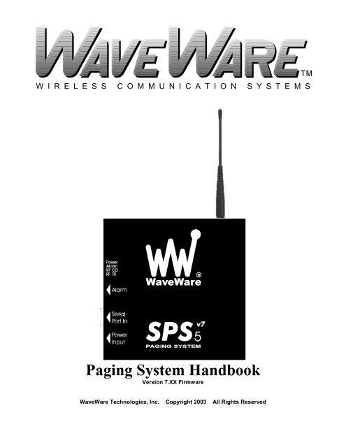
Appendix L – Connectors and IndicatorsThe <strong>SPS</strong>-5<strong>v7</strong> paging system connectors include the following:Power (12VDC, 2 pin positive lock Molex)Serial Data (DB-9 female)Alarm Monitoring (RJ-45 jack, 8 pin). Pins 1 and 2 are the Opto-isolated contact monitoring input pins.The <strong>SPS</strong>-5<strong>v7</strong> paging system LED indicators include the following:Power (red LED)AlarmCarrier DetectRF TXThe pinout of the RJ-45 connector is:1 Opto input #12 Opto input #23 RS-485- (not used in this model)4 GND5 +12V, current limited (available as voltage source for alarm input circuit)6 RS-485+ (not used in this model7 No connection8 GNDThe pinout of the DB-9F connector is:1 CD (not used)2 RD (data output by paging system, typically required)3 TD (data received by paging system, required)4 DTR (not used)5 GND (required)6 DSR (signal output by paging system, requirement depends on host system)7 RTS (signal input to paging system, required only if hardware flow control mode is active)8 CTS (signal output by paging system, required only if hardware flow control mode is active)9 RI (not used)Appendix L – Connectors and Indicators - 31


