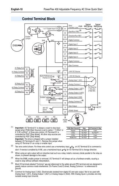
English-10<strong>PowerFlex</strong> <strong>400</strong> <strong>Adjustable</strong> <strong>Frequency</strong> <strong>AC</strong> <strong>Drive</strong> Quick StartControl Terminal BlockENBLEnable (4)Jumper#1 Relay N.O.R1#1 Relay CommonR2#1 Relay N.C.R3#2 Relay N.O.R4#2 Relay CommonR5#2 Relay N.C.R6SNKSRCSNK+24VEarth Referenced +10VFrames D & E (5) 0-10V0-20mAIsolated1 of 7 Digital Input Circuits30V DC50mANon-inductiveSRC0-10V0-20mA0-10V0-20mA0102030405060708091011121314151617181920Stop/Function Loss (1)(4)Start/Run FWD (2)Direction/Run REVDigital CommonDigital Input 1Digital Input 2Digital Input 3Digital Input 4Digital CommonOpto Common+24V DC Source+10V DC SourceAnalog Input 1 (AI1)Analog Common 1Analog Output 1 (AO1)Analog Output 2 (AO2)Analog Input 2 (AI2)Analog Common 2 (6)Opto OutputRS485 ShieldTypicalSRC WiringPot must be1-10k ohm2 Watt Min.TypicalSNK WiringCommon(3)24VAO110V 20MAAO210V 20MAAI110V 20MAAI210V 20MARS485(DSI)(1)(2)(3)(4)(5)(6)Important: I/O Terminal 01 is always a coast to stop inputexcept when P036 [Start Source] is set to option 1 “3-Wire” or6 “2-W Lvl/Enbl”. In three wire control, I/O Terminal 01 iscontrolled by P037 [Stop Mode]. All other stop sources arecontrolled by P037 [Stop Mode].Important: The drive is shipped with a jumper installedbetween I/O Terminals 01 and 11. Remove this jumper whenusing I/O Terminal 01 as a stop or enable input.Two wire control shown. For three wire control use a momentary inputstart. If reverse is enabled by A166, use a maintained inputP036 [Start Source] Stop I/O Terminal 01 StopKeypad Per P037 Coast3-Wire Per P037 Per P037 (4)2-Wire Per P037 CoastRS485 Port Per P037 Coaston I/O Terminal 02 to command afor I/O Terminal 03 to change direction.When using an opto output with an inductive load such as a relay, install a recovery diode parallel to the relay asshown, to prevent damage to the output.When the ENBL enable jumper is removed, I/O Terminal 01 will always act as a hardware enable, causing acoast to stop without software interpretation.Most I/O terminals labeled “Common” are not referenced to the safety ground (PE) terminal and are designed togreatly reduce common mode interference. On Frame D and E drives, Analog Common 1 is referenced toground.Common for Analog Input 2 (AI2). Electronically isolated from digital I/O and opto output. Not to be used withAnalog Input 1 (AI1), Analog Output 1 (AO1) or Analog Output 2 (AO2). With Analog Input 2, provides one fullyisolated analog input channel.
<strong>PowerFlex</strong> <strong>400</strong> <strong>Adjustable</strong> <strong>Frequency</strong> <strong>AC</strong> <strong>Drive</strong> Quick StartEnglish-11Control I/O Terminal DesignationsNo. Signal Default Description Param.01 Stop (1) /Coast Factory installed jumper or a normally closed input must P036 (1)Function Lossbe present for the drive to start.Program with P036 [Start Source].02 Start/Run FWD – HAND Mode: Command comes from Integral Keypad.AUTO Mode: I/O Terminal 02 is active.Program with P036 [Start Source].P036, P03703 Direction/Run REV Rev Disabled To enable reverse operation, program with A166[Reverse Disable].Program with P036 [Start Source].P036, P037,A16604 Digital Common – For digital inputs. Tied to I/O Terminal 09.Electronically isolated with digital inputs from analog I/Oand opto output.05 Digital Input 1 Purge (2) Program with T051 [Digital In1 Sel]. T05106 Digital Input 2 Local Program with T052 [Digital In2 Sel]. T05207 Digital Input 3 Clear Fault Program with T053 [Digital In3 Sel]. T05308 Digital Input 4 Comm Port Program with T054 [Digital In4 Sel]. T05409 Digital Common – For digital inputs. Tied to I/O Terminal 04.Electronically isolated with digital inputs from analog I/Oand opto output.10 Opto Common – For opto-coupled outputs. Electronically isolated withopto output from analog I/O and digital inputs.11 +24V DC – <strong>Drive</strong> supplied power for digital inputs.Referenced to Digital Common. Max. Output: 100mA.12 +10V DC – <strong>Drive</strong> supplied power for 0-10V external potentiometer.Referenced to Analog Common. Max. Output: 15mA.P03813 Analog Input 1 0-10V External 0-10V (unipolar), 0-20mA or 4-20mA inputsupply or potentiometer wiper. Default input is 0-10V.For current (mA) input, set AI1 DIP Switch to 20mA.Program with T069 [Analog In 1 Sel].Input Impedance: 100k ohm (Voltage Mode)250 ohm (Current Mode)14 Analog Common 1 – Common for Analog Input 1 and Analog Output 1 and 2.Electrically isolated from digital I/O and opto output.15 Analog Output 1 OutFreq 0-10 Default analog output is 0-10V.For current (mA) value, set AO1 DIP Switch to 20mA.Program with T082 [Analog Out1 Sel].Maximum Load: 4-20mA = 525 ohm (10.5V)0-10V = 1k ohm (10mA)16 Analog Output 2 OutCurr 0-10 Default analog output is 0-10V.For a current (mA) value, set AO2 DIP Switch to 20mA.Program with T085 [Analog Out2 Sel].Maximum Load: 4-20mA = 525 ohm (10.5V)0-10V = 1k ohm (10mA)17 Analog Input 2 0-10V Optically isolated external 0-10V (unipolar), ±10V(bipolar), 0-20mA or 4-20mA input supply orpotentiometer wiper. Default input is 0-10V.For current (mA) input, set AI2 DIP Switch to 20mA.Program with T073 [Analog In 2 Sel].Input Impedance: 100k ohm (Voltage Mode)250 ohm (Current Mode)T069, T070,T071, T072P038,T051-T054,A152T082, T084,T085, T086,T087T073, T074,T075, T07618 Analog Common 2 – For Analog Input 2. Electronically isolated from digital I/Oand opto output. With Analog Input 2, provides one fullyisolated analog input channel.19 Opto Output At <strong>Frequency</strong> Program with T065 [Opto Out Sel]. T065, T066,T06820 RS485 (DSI) Shield – Terminal connected to Safety Ground - PE when usingthe RS485 (DSI) Communication Port.(1)(2)See Footnotes (1) and (4) on previous page.See the User Manual for Important information regarding Stop commands and the [Digital Inx Sel] Purge option.