Vector Dynamics Foundation System Installation Instructions for WZ I
Vector Dynamics Foundation System Installation Instructions for WZ I
Vector Dynamics Foundation System Installation Instructions for WZ I
- No tags were found...

You also want an ePaper? Increase the reach of your titles
YUMPU automatically turns print PDFs into web optimized ePapers that Google loves.
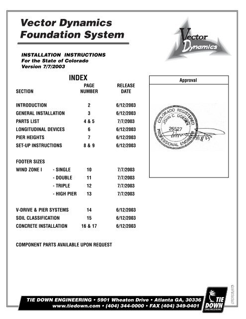
INSTALLATION INSTRUCTIONSFor the State of ColoradoVersion 7/7/2003INDEXPAGE RELEASESECTION NUMBER DATEApprovalINTRODUCTION 2 6/12/2003GENERAL INSTALLATION 3 6/12/2003PARTS LIST 4 & 5 7/7/2003LONGITUDINAL DEVICES 6 6/12/2003PIER HEIGHTS 7 6/12/2003SET-UP INSTRUCTIONS 8 & 9 6/12/2003FOOTER SIZESWIND ZONE I - SINGLE 10 7/7/2003- DOUBLE 11 7/7/2003- TRIPLE 12 7/7/2003- HIGH PIER 13 7/7/2003V-DRIVE & PIER SYSTEMS 14 6/12/2003SOIL CLASSIFICATION 15 6/12/2003CONCRETE INSTALLATION 16 & 17 6/12/2003COMPONENT PARTS AVAILABLE UPON REQUEST070703,573
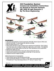
Tie Down Engineering, Inc.VECTOR DYNAMICS INSTALLATION DESIGN INSTRUCTIONSIntroductionThese instructions describe the proper use of the lateral and longitudinal foundation system. You may also referto the home manufacturer’s installation manuals that include the <strong>Vector</strong> <strong>Dynamics</strong> system as an alternate foundationsystem.GeneralThe <strong>Vector</strong> <strong>Dynamics</strong> <strong>Foundation</strong> <strong>System</strong> provides the support to resist lateral, longitudinal and over-turningmovement of the home as required by the Federal Manufactured Home Construction and Safety Standards in aspecified wind zone when the system is used as described in these instructions. Please verify state or local windload requirements prior to installation of the home.The <strong>Vector</strong> <strong>Dynamics</strong> <strong>Foundation</strong> <strong>System</strong> resists lateral & longitudinal wind loads by anchoring the two longitudinalmain rails. The system is approved to be used on single or multi section homes:Nominally 12 feet to 16’ feet wide- (single section) with main rail spacing of 95 inches or greateron center; multi section main rail spacing of 75 inches or greater on center.Nominal 8 foot or less top plate height at sidewalls with main rail depth of 12” or less.Maximum roof slope of 20 degrees (4.4” in 12” slope).Maximum eave width (roof overhang of sidewall) of 12” <strong>for</strong> Zone I, 8” <strong>for</strong> Zone II, 6” <strong>for</strong> Zone III.Maximum pier height under main rails-see page 6.The <strong>Vector</strong> <strong>Dynamics</strong> <strong>Foundation</strong> <strong>System</strong>s may be used as a part of the vertical or gravity support system consideringthat each <strong>Vector</strong> <strong>Dynamics</strong> pad has two (2) or (3) square feets bearing area.To inquire about the use of the <strong>Vector</strong> <strong>Dynamics</strong> <strong>Foundation</strong> <strong>System</strong>s with homes of four or more sections,other widths, or on homes requiring pier heights which are not included in these instructions, contact Tie DownEngineering, Inc. at 1-800-24l-1806.The <strong>Vector</strong> <strong>Dynamics</strong> <strong>Foundation</strong> <strong>System</strong> has not been designed <strong>for</strong> use on exposure “D” homes within 1500feet of the coastline.Additional vertical anchor ties that are unique to a home’s design may be required by the home manufacturer.These locations may include shear walls, marriage line ridge beam support posts, end frame ties and rim plates.Page 2 Colorado 06-12-03
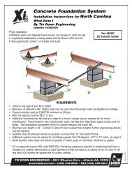
GENERAL INSTALLATION INSTRUCTIONSSITE PREPARATIONIt is necessary that the home site be properly graded and sloped to prevent water and moisture from standing orflowing beneath the home.FOOTINGS AND FROST LINESThe <strong>Vector</strong> <strong>Dynamics</strong> <strong>Foundation</strong> <strong>System</strong> was designed to be placed directly on top of the ground (or pouredconcrete) after clearing all loose vegetation. In areas with frost heave, use <strong>Vector</strong> <strong>for</strong> Poured Concrete (seepages 16 & 17) to comply with local requirements <strong>for</strong> footer depth.FOUNDATION/FOOTING SPECIFICATIONS FOR VECTOR PADS<strong>Vector</strong> Pads are used in place of conventional foundation pads. One <strong>Vector</strong> pad provides two or three squarefeet of bearing support. <strong>Vector</strong> <strong>System</strong>s should be spaced as symmetrically as possible along the length of thehome. For pier locations in between the <strong>Vector</strong> <strong>System</strong>s, use the normal foundation pads.LUMBER/MOISTURE - TERMITE SHIELDTo cut PVC or lumber (2 - 2x4's,1 - 4x4 or 1 adjustable steel commpression member per <strong>Vector</strong> system) <strong>for</strong> thecenter compression section,when using concrete blocks <strong>for</strong> piers, measure center to center frame (I-beam) distanceand subtract 16". When using METAL PIER STANDS, measure center to center frame distance and add 16".ALL WOOD MUST BE PRESSURE TREATED, GROUND CONTACT RATED .Tip: Pre-cut your lumber and mark as to brand or model of homes you will be installing. If frame widths are thesame, the pre-cut boards will also be the same length in each <strong>Vector</strong> set-up.STRAP INSTALLATIONAll frame ties and diagonal straps must go from the anchor to the top of the I-Beam. See illustration below.1. Attach frame hook to top inboardlocation of "I" beam. (Frame hook must beattached to frame at points closest to floor support.)2. Keeping in line with the hook, wrap galvanizedstrap completely around "I" beam.3. Pull strap past anchor head approximately ten inchesbe<strong>for</strong>e cutting to allow enough strap to give a minimumof five turns around the slotted anchor bolt.4. Thread loose end through slotted bolt so that the strap isflush with the other side of the bolt.5. Tighten slotted tensioning bolt a minimum of five full turns.Page 3 Colorado 06-12-03
<strong>Vector</strong> <strong>Dynamics</strong><strong>Foundation</strong> <strong>System</strong>sComponent Parts List<strong>Vector</strong> <strong>System</strong> 2000Part # 59018Single piece pads with strapsand slotted bolts<strong>Vector</strong> <strong>System</strong>Part # 59007Concrete <strong>Vector</strong> <strong>System</strong>Part # 59036Single piece pads withswivel straps and slotted boltsPart # 59008Single piece pads withoutswivel straps and slotted boltsConcrete <strong>Vector</strong> <strong>System</strong>Part # 59049Double block pads withswivel straps and slotted boltsPart # 59006Double block pads withoutswivel straps and slotted boltsLongitudinal StabilizationHardware Kit <strong>for</strong> ConcretePart # 59023(<strong>for</strong> use with 59006 & 59008)Page 4 Colorado 7-7-03
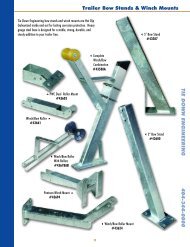
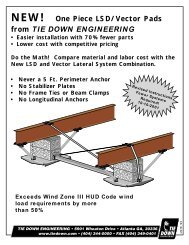
Longitudinal Stabilizer DevicesAs an alternate to installing longitudinal anchors and stabilizer plates, the installer may uselongitudinal stabilizing devices, including Tie Down's LSD (Longitudinal Stabilization Device). Theuse of LSD systems on a single or multi section home replaces longitudinal anchors, stabilizerplates and straps.LSDCombine <strong>Vector</strong> <strong>Dynamics</strong>& LSD2311. Longitudinal <strong>Foundation</strong> Pad2. Beam Clamp (2 per system)3. Longitudinal Strut (2 per system)4. Tie Bracket (2 per system)4Note: LSD pads provide 3 sq. ft. of bearingsupport per system and can be used tocombine <strong>Vector</strong> & LSD.Examples of Possible Placement:(Contact TIE DOWN <strong>for</strong> placment in other Wind Zones)Wind ZoneITriple SectionWind ZoneISingle SectionWind ZoneIDouble SectionWind ZoneITag Section18 Ft. Max. 32 Ft. Max.For greater widths usetriple section design.48 Ft. Max.Page 6 Colorado 06-12-03
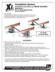
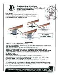
50 in.max.Figure 1Maximum Pier Height<strong>Vector</strong> <strong>Dynamics</strong> <strong>Foundation</strong> <strong>System</strong>s may be used on single section homes in Wind Zone I which require pierheights (from surface of <strong>Vector</strong> pads to top of concrete or metal pier) not to exceed 50 inches under one orboth main rail(s). Note that a ground anchor must be used at each <strong>Vector</strong> system location where the pier heightexceeds 24 inches <strong>for</strong> single section homes. On multi-section homes in Wind Zone I, an anchor must be usedat each <strong>Vector</strong> <strong>System</strong> location with pier heights above 46” with the following exception: double section homesthat are 24’ wide, in Wind Zone I, have a maximum pier height without anchors of 38”. See page 13 <strong>for</strong> doublesection home high pier set instructions.24”50 in.max.26” MaximumUnequal Pier HeightsFigure 2Homes with unequal pier heights are limited to 50” maximum pier height. The difference between the taller pierand the shorter pier cannot exceed 26”. Anchors are 3/4 x 30” min with 12” stabilizer plates. Maximum designload is 3150#, Wind Zone I charts in this instruction manual are based on a <strong>Vector</strong> design load of 3150#.Page 7 Colorado 06-12-03
Set-Up <strong>Instructions</strong> <strong>for</strong><strong>Vector</strong> <strong>System</strong> #59018Long U-BoltsABCD1. Set <strong>Vector</strong> PadsClear all vegatation where pads will rest. Place a longU-bolt in pad as shown. Press or hammer pad intothe ground.2. Set Block or piers on pads.Center foundation blocks or piers on pads. Place precutcenter compression member between blocks, restingon pads, centers between U-bolts as shown.4. Inside brackets & strapsAttach the inside tie brackets to the U-bolts over thecompresion member. Attach a strap w/hook or swivelstrap w/nut & bolt. Place other end of the strap overopposite I-beam & down to outside tension bracket.Cut strap 12 - 15 inches past bracket. Attach strap &slotted bolt in bracket. Tighten strap until tight with4-5 wraps around bolt. Repeat with opposite strap.3. Outside Tension BracketAttach outside tension bracket as shown to outside ofpads.Page 8 Colorado 06-12-03
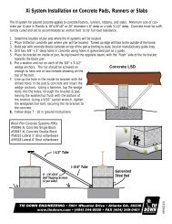
Set-Up <strong>Instructions</strong> <strong>for</strong> the<strong>Vector</strong> <strong>Dynamics</strong> <strong>Foundation</strong> <strong>System</strong>#590071. SET VECTOR FOUNDATION PADSClear all loose vegetation from the immediate areawhere your <strong>Vector</strong> foundation pads will rest. Press orhammer pads into the ground. Tip: Place a 3/8" nut oneach U-bolt to keep it in place while you position the<strong>Vector</strong> pads.ShortU-boltLongU-boltShortU-bolt2 square footpad placementor (1) 3 squarefoot pad2. SET BLOCKS (OR PIERS) ONVECTOR FOUNDATION PADSCenter the foundation blocks over the<strong>Vector</strong> pads. Place the pre-cut 4x4,2x4's (side by side), Schedule 40 PVC(w/PVC adapter plate, part #59281) or1 adjustable steel compressionmember, (part #59043) tightly betweenthe blocks, with ends resting on the<strong>Vector</strong> pads, and centered on eachU-bolt.3. OUTSIDE TENSION BRACKETSAttach an Outside Tension Bracket to theU-bolts on the outside of the foundationblocks and <strong>Vector</strong> pads. Place one of theshort 6"- 2x4's between the bracket and<strong>Vector</strong> pad. Adjust the short 2x4 so thatit pushes against the foundation blocks,removing any space between the piersand center compression section. Tightenthe 3/8" bolts.4. INSIDE BRACKETS AND STRAPSAttach the Inside Tie Brackets to theU-bolts over the pre-cut boards or PVC.Attach a strap with hook to each inside tiebracket. Tighten bracket. When usinglooped strap and a crimp seal, in place ofthe hook, place a 3" long section of strap,folded in half and inserted between thestrap and inside tie bracket. Place otherend of strap over the opposite I-beam andcontinue down to outside of thefoundation blocks. Attach the strap to theOutside Tension brackets using the slottedbolt and nut provided. Wind strap aminimum of five times around the bolt.Continue tightening the slotted bolt untilall slack has been removed and the strapis tight.5. SET ANCHORSRefer to section home drawings <strong>for</strong> anchor installation in<strong>for</strong>mation. Stabilizer plates are required <strong>for</strong> diagonal tiesonly. Preload anchor against stabilizer plate. Make certain all slack is removed and strap is tight. For single sectionhomes in rocky soil conditions in Wind Zone 1 only (Soil Classifications 2 & 3 only), use minimum of 3 each V-Driveanchors per side. See drawing on page 5 <strong>for</strong> placement.Page 9 Colorado 06-12-03
2 ft. max. typ.See Note & Chart2 sq. ft. pad48" max.Min. Numberof <strong>Vector</strong>For Length of Home<strong>System</strong>s Req’d 84” Sidewall 90” Sidewall 96” Sidewall3 20’ - 60’ 20’ - 56’ 20’ - 53’4 61’ - 80’ 57’ - 76’ 54’ - 71’5 81’ - 90’ 77’ - 90’ 72’ - 89’NOTE: <strong>Vector</strong> <strong>System</strong>s should bespaced as symmetrically as possiblealong the length of the home.Pier spacing must be consistentwith home manufacturers'requirements.Soil Classifications: 2, 3, 4A, & 4BSoil Bearing Capacity: 1,000 PSF minimumAnchors Required: 0 - 24” Pier Height: None*, Over 24” 2 per side*If rail spacing is less than 95" use 30" with2-4" helix anchor (59095) (2 per side),12 stabilizer plates (59292) & 1-1/4" frame tiesMaterials: Each <strong>Vector</strong> <strong>Foundation</strong> <strong>System</strong> requiresOne <strong>Vector</strong> Kit2 ea. 1-1/4in. ties (4725 lb. min. break), length will vary with pier height1 ea. 4 x 4 pressure treated wood compression memberor 2 ea. 2 x 4 pressure treated wood compression member, or Schedule 40 PVC.Page 10 Colorado 07-07-03
2 ft. max. typ.2 sq. ft. padMin. Numberof <strong>Vector</strong><strong>System</strong>s Req’dFor Length of Home90” 96”S idewall Sidewall2 20’ - 34’ 20’ - 32’3 35’ - 51’ 32’ - 48’4 52’ - 68’ 49’ - 64’5 69’ - 80’ 65’ - 80’Soil Classifications: 2, 3, 4A, & 4BSoil Bearing Capacity: 1,000 PSF minimumAnchors Required*: None (*Marriage wall anchors may be required by home manufacturer)Materials: Each <strong>Vector</strong> <strong>Foundation</strong> <strong>System</strong> requiresOne <strong>Vector</strong> Kit, 2 slotted bolts2 ea. 1-1/4in. ties (4725 lb. min. break), length will vary with pier height1 ea. 4 x 4 pressure treated wood compression memberor 2 ea. 2 x 4 pressure treated wood compression memberor Schedule 40 PVC.Page 11 Colorado 7-7-03
WIND ZONE I (High Pier Sets)<strong>Vector</strong> <strong>Dynamics</strong> <strong>System</strong>s Required<strong>for</strong> Double Section Homes(High Pier Sets with Diagonial Ties)2 ft. max. typ.Min. Number For length of homeof<strong>Vector</strong> 90" 96"<strong>System</strong>s Req'd Sidewall Sidewall2 20'-54' 20'-50'3 55' - 80' 51' - 74'4 ------- 75' - 80'5 ------- --------Diagonal TiesSpaced @ 16'-0" O/C Max.NOTE: Pier height includes depth of I-Beam asmeasured from <strong>Vector</strong> pad or anchor head (whicheverworst) to the bottom of the level floor.44" max. <strong>for</strong> 24' wides60" max. <strong>for</strong> 28' wides & widerSoil Classifications: 2, 3, 4A, & 4BSoil Bearing Capacity: 1,000 PSF minimumAnchors Required*: 30” with 2-4” helix anchor (59095), 12” stabilizer plates(59292) 1-1/4” frame tie with connectorI-BeamSpacing2 sq. ft. pad45˚Min.Materials: Each <strong>Vector</strong> <strong>Foundation</strong> <strong>System</strong> requiresOne <strong>Vector</strong> Kit, 2 slotted bolts2 ea. 1-1/4in. ties (4725 lb. min. break), length will vary with pier height1 ea. 4 x 4 pressure treated wood compression memberor 2 ea. 2 x 4 pressure treated wood compression memberorSchedule 40 PVC Pipe.Page 13 Colorado 7-7-03
VECTOR DYNAMICS INSTALLATION DESIGN INSTRUCTIONS<strong>Vector</strong> Dynamic <strong>Foundation</strong> <strong>System</strong>s may be used only on homes set on soils classified as Class 2, 3, 4A and 4B asdescribed in the table below:SOIL CLASSIFICATIONSSoil Class Types of Soils Blow Count (ASTM Soil Test Probe (1)D2586) Torque Value (2)1 Sound hard rock...... NA NAVery dense and/or 40-up More than 550 lbs - in.cemented sands, coarse2 gravel and cobbles,preloaded silts, clays,and coralsMedium-dense coarse 24-39 350-549 lbs - in.3 sands, sandy gravels, verystiff silts and clays4A Loose to medium dense 14-23 275-349 lbs - in.sands, firm to stiff clays4B and silts, alluvian fill 175-275 lbs - inPeat, organic silts, 0-44 175 lbs - in.5 inundated silts, loose fine and lowersand, alluvium, loess,varied clays, fill, fly ash.(1) The purpose of the soil test probe is to gauge the strength of the soil below the surfaceand near the anchor’s helical plate. The strength of the soil is estimated in terms of its resistance to penetration(flow) under load by means of the torque probe and is measured in lb-in. The test probe has a helix on it. Theoverall length of the helical Section is 10.75 in.; the major diameter is 1.25 in.; the minor diameter is 0.81 in.;the pitch is 1.75 in. The shaft must be of suitable length <strong>for</strong> anchor depth.(2) A measure synonymous with moment of a <strong>for</strong>ce when distributed around the shaft of thetest probe.Footer Size:16x16 = 256 sq. in.or 16x18 = 288 sq. in.EQUALS2-<strong>Vector</strong> Pads # 59275288 sq. in. or1 <strong>Vector</strong> Pad # 59130<strong>Vector</strong> <strong>Foundation</strong> Pads Equivalent to Footer Pads*Footer Size:20x20 = 400 sq. in.or 17x25=425 sq. in.EQUALS1-<strong>Vector</strong> Pad # 59271432 sq. in.<strong>Vector</strong> Pad(s) exceed the surface area required when used as the equivalent listed above.*<strong>Foundation</strong>s in soil with a bearing capacity of less than 1,000 PSF must be designed by a Registered Professional Engineer familiar with siteconditonsPage 15 Colorado 06-12-03