Xi2 Foundation System - Tie Down Engineering Restricted Web Sites
Xi2 Foundation System - Tie Down Engineering Restricted Web Sites
Xi2 Foundation System - Tie Down Engineering Restricted Web Sites
- No tags were found...

Create successful ePaper yourself
Turn your PDF publications into a flip-book with our unique Google optimized e-Paper software.
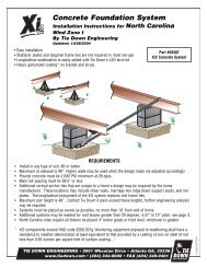
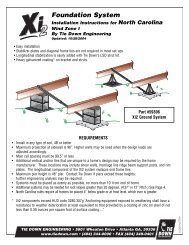
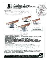
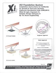
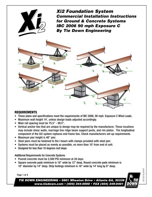
Installation of <strong>Xi2</strong> Concrete <strong>System</strong>s<strong>Xi2</strong> Concrete <strong>System</strong>1. Identify the number of systems to be used on the home using the chart provided.2. Identify the location where the systems will be installed.3. Build pier according to State, Lateral Local or unit manufacturers guidelines.4A. Drill two 3/8”x 3” deep holes in the concrete using holes in galvanized bracketas a guide. Attach bracket to concrete pad using 3/8”x3-1/2” wedge anchorsprovided. Place nut & washer on anchor, leave enough room for 1 to 2 threadsshowingLongitudinalon top of bolt. Using a hammer, tap the wedge bolts into holethrough bracket, leaving nut & washer flush with I-Beam bracket. Using a 9/16” socketwrench, tighten wedge/anchor bolt, securing bracket to the concrete.4B. For wet set: align bracket and submerge legs completely in concrete. Bottomof the bracket should rest on the surface.5. Attach the end of the smaller tube to the bracket mounted on the pad, using thegrade 5, 1/2” x 2-1/2” bolt/nut provided.6. Attach the flag end of the larger tube to the opposite I-beam using the “J” boltover the top of the I-beam with the nut & washer provided. (Figure 1 next page)7. Install a minimum of four (#12 x 1” tek screws) self-tapping screws into theholes provided in the lateral strut so that the two tubes are connected together8. Install frame bracket clamps on I-beam on the inside of block/pier.9. Insert strut in frame bracket clamp and attach with nut & bolt. Attach oppositeend to concrete bracket.10. Pull the frame bracket clamp with fastened strut outward to remove any slack.11. Tighten all nuts and bolts on system.Minimum Distancefrom edge: 1-1/2”Page 3 of 4
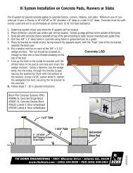
Figure 1J-BoltNut & WasherBeam ClampBracket1-3/4" TubeLateral StrutsLateralLongitudinal4 - #12 x 1"Tek Screws1-1/2" TubeI-Beam<strong>Xi2</strong> Installation Placement<strong>Xi2</strong> Stabilization Pier Placement for Ground or Concrete30” Anchor*<strong>Xi2</strong> PierPlacement3rd <strong>System</strong>Placement(When Needed)Up to 12’Wall Height14’Wall HeightSingle Section* - WZ I0 -80’ Box 2 <strong>Xi2</strong> <strong>System</strong>s0 - 72’ Box 2 <strong>Xi2</strong> <strong>System</strong>s76’ - 80’ Box 3 <strong>Xi2</strong> <strong>System</strong>sNumber of <strong>Xi2</strong> <strong>System</strong>s RequiredDouble Section - WZ I0 - 80’ Box 2 <strong>Xi2</strong> <strong>System</strong>s0 - 72’ Box 2 <strong>Xi2</strong> <strong>System</strong>s76’ - 80’ Box 3 <strong>Xi2</strong> <strong>System</strong>sTriple Section - WZ I0 - 80’ Box 2 <strong>Xi2</strong> <strong>System</strong>s0 - 72’ Box 2 <strong>Xi2</strong> <strong>System</strong>s76’ - 80’ Box 3 <strong>Xi2</strong> <strong>System</strong>s* - 30” anchor with vertical strap or frame tie with stabilizer plate, within 10’ of end of unit on single sections.NOTE: Wall heights are the eave height for a building without solid skirting. If solid skirting is installed, add theskirting height and use that sum as the wall height. Tear away skirting such as vinyl is not considered solid skirting.Diagram represents single section up to 16’ width, double section up to 32’ width, and triple section up to 48’.For multiple section of units, determine the number of systems based on each group of 3 modules, with theremainder based on a double or single section (without anchors).Page 4 of 4