Xi2 Steel Pier System WZ's I, II, III - Tie Down Engineering
Xi2 Steel Pier System WZ's I, II, III - Tie Down Engineering
Xi2 Steel Pier System WZ's I, II, III - Tie Down Engineering
- No tags were found...

Create successful ePaper yourself
Turn your PDF publications into a flip-book with our unique Google optimized e-Paper software.
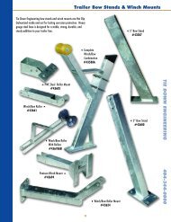
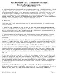
<strong>Xi2</strong> Longitudinal <strong>Pier</strong> PlacementSingle SectionUp to 16’ NominalDouble SectionUp to 32’ NominalTriple Sectionup to 48’ NominalWhen pier with LSD struts is used only as longitudinal stabilization, systems must be as evenly spaced aspossible, no more than 10’ from the end of the home.<strong>Xi2</strong> Lateral Stabilization <strong>Pier</strong> Placement30”Anchor*<strong>Xi2</strong> <strong>Pier</strong>Placement3rd <strong>System</strong>for PlacementSingle Section Home - WZ I & <strong>II</strong>0 - 76’ Box 2 <strong>Xi2</strong> <strong>System</strong>sOver 76’ Box 3 <strong>Xi2</strong> <strong>System</strong>sSingle Section Home - WZ <strong>II</strong>I0 - 64’ Box 2 <strong>Xi2</strong> <strong>System</strong>sOver 64’ Box 3 <strong>Xi2</strong> <strong>System</strong>sDouble Section Home - WZ I & <strong>II</strong>0 - 76’ Box 2 <strong>Xi2</strong> <strong>System</strong>sOver 76’ Box 3 <strong>Xi2</strong> <strong>System</strong>sDouble Section Home - WZ <strong>II</strong>I0 - 64’ Box 2 <strong>Xi2</strong> <strong>System</strong>sOver 64’ Box 3 <strong>Xi2</strong> <strong>System</strong>sTriple Section Home - WZ I & <strong>II</strong>0 - 76’ Box 2 <strong>Xi2</strong> <strong>System</strong>sOver 76’ Box 3 <strong>Xi2</strong> <strong>System</strong>sTriple Section Home - WZ <strong>II</strong>I0 - 64’ Box 2 <strong>Xi2</strong> <strong>System</strong>sOver 64’ Box 3 <strong>Xi2</strong> <strong>System</strong>s* For Wind Zone I - 30” anchor w/vertical strap or frame tie w/stabilizer plate, within 10’ of end of home on single sections.NOTE:Diagram represents single section up to 16’ width, double section up to 32’ width,and triple section homes up to 48’ width.080906,D848
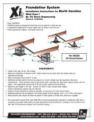
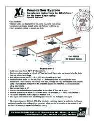
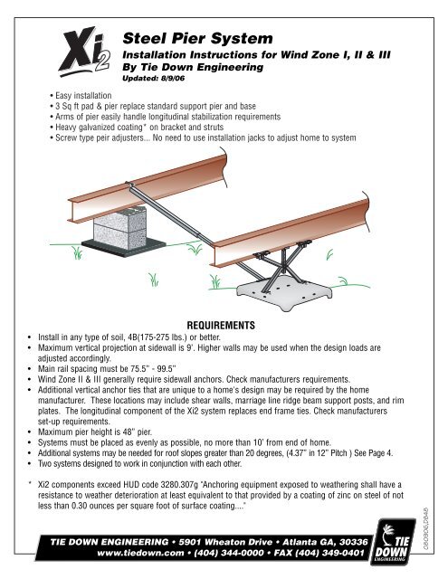
Installation of Longitudinal <strong>System</strong> (Figure 1)1. Identify the number of systems to be used on the home using the chart provided.2. Identify on the location where the longitudinal systems will be installed.3. Clear all organic matter and debris from the pad site.4. Place pad centered under beam using the centering mark imprinted on the pad.5. Press or drive pan into ground until level and flush with prepared surface.6. Slide Xi-<strong>System</strong> pier feet into slots in pad so that the Xi-system pier is centered under the I-beam.7. Raise telescoping extension post to contact the bottom of I-beam, secure with bolt provided, tightenbolt nut. (Figure 1)8. Turn hex nut on pier height adjuster until Xi-<strong>System</strong> pier is rigid between pad and I-beam.9. Install Gator Beam clamps to I-beam on each side of the Xi-<strong>System</strong> pier. Do not tighten nuts atthis time. (Figure 2)10. Connect struts (open side down) to each side of the Xi-<strong>System</strong> pier using the U- bolt provided. Struts areattached to the upper hole in each pier leg and to the flanges on the beam clamps. (Figure 1)11. Tighten all nuts and bolts on the struts and beam clamps.Installation of Lateral <strong>System</strong> (Figure 3)1. Assemble lateral strut by sliding smaller (1-1/2”) tube into the larger (1-3/4”) tube. Holes should be on thesides of the larger tube and the “flag” up on the larger tube.2. Attach the end of the smaller tube to the inside of the pan using u-bolts and nuts provided.3. Attach the flag end of the larger tube to the opposite I-beam using the “J” bolt over the top of the I-beamwith the nut & washer provided. (Figure 4)4. Install a minimum of four(1/4”x3/4’) self-tapping screws into the holes provided in the lateral strut so that the twotubes are connected together. (Figure 1)(Figure 2)(Figure 1)LongitudinalStruts<strong>Pier</strong> BaseFoundationBase PadBoltHeightAdjuster 0-3"<strong>Pier</strong> BaseExtensionPost1-3/4" TubeFrameBracketStrutJ-Bolt(Figure 4)Beam ClampBracket4 - #12 X 1”Tek Screws(2 per side)Lateral Struts1-1/2" Tube(Figure 3)All Components Hot Galvanized Coated080906,D848
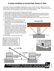
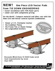
<strong>Xi2</strong> <strong>System</strong> Requirements for Roof Pitches Higher than 20 degreesModuleLength(Feet)Wind Zone I Wind Zone <strong>II</strong> Wind Zone <strong>II</strong>I5:12 6:12 7:12 9:12 5:12 6:12 7:12 9:12 5:12 6:12 7:12 9:1234 2 2 2 2 2 2 2 2 2 2 3 336 2 2 2 2 2 2 2 3 2 2 3 338 2 2 2 3 2 2 2 3 2 3 3 340 2 2 2 3 2 2 2 3 3 3 3 342 2 2 3 3 2 2 3 3 3 3 3 344 2 2 3 3 2 2 3 3 3 3 3 346 2 3 3 3 2 3 3 3 3 3 3 448 2 3 3 3 3 3 3 3 3 3 3 450 3 3 3 3 3 3 3 3 3 3 3 452 3 3 3 3 3 3 3 3 3 3 4 454 3 3 3 3 3 3 3 3 3 3 4 456 3 3 3 3 3 3 3 3 3 3 4 458 3 3 3 3 3 3 3 3 3 3 4 460 3 3 3 3 3 3 3 3 3 3 4 562 3 3 3 3 3 3 3 3 4 4 4 564 3 3 4 4 3 3 4 4 4 4 4 566 3 3 4 4 3 3 4 4 4 4 4 568 3 4 4 4 3 4 4 4 4 4 5 570 3 4 4 4 3 4 4 4 4 4 5 572 3 4 4 4 4 4 4 5 4 4 5 574 4 4 4 5 4 4 4 5 4 5 5 576 4 4 4 5 4 4 4 5 4 5 5 678 4 4 4 5 4 4 4 5 4 5 5 680 4 4 4 5 4 4 4 5 4 5 5 6<strong>Steel</strong> <strong>Pier</strong> <strong>System</strong>s P/N’s#59321 Xi, 12” <strong>Pier</strong>#59314 Xi, 25.5” <strong>Pier</strong>#59317 Xi, 36” <strong>Pier</strong>#59315 Xi, 5’ Lateral Strut#59318 Xi, 6’ Lateral StrutJ-BoltBeam ClampBracketLateral StrutBlock <strong>Pier</strong> <strong>System</strong>s P/N’s#59319 Xi, Lateral w/5’ Strut#59320 Xi, Lateral w/6’ StrutLongitudinal StrutFoundationBase Pad080906,D848