Xi2 Foundation System Installation for Wind Zone I
Xi2 Foundation System Installation for Wind Zone I
Xi2 Foundation System Installation for Wind Zone I

You also want an ePaper? Increase the reach of your titles
YUMPU automatically turns print PDFs into web optimized ePapers that Google loves.
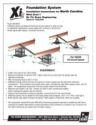
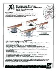
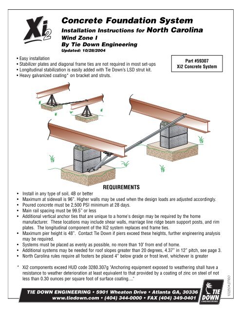
Concrete <strong>Foundation</strong> <strong>System</strong><strong>Installation</strong> Instructions <strong>for</strong> North Carolina<strong>Wind</strong> <strong>Zone</strong> IBy Tie Down EngineeringUpdated: 10/28/2004• Easy installation• Stabilizer plates and diagonal frame ties are not required in most set-ups• Longitudinal stabilization is easily added with Tie Down’s LSD strut kit.• Heavy galvanized coating* on bracket and struts.Part #59307<strong>Xi2</strong> Concrete <strong>System</strong>• Install in any type of soil, 4B or betterREQUIREMENTS• Maximum at sidewall is 96”. Higher Lateral walls may be used when the design loads are Lateral adjusted accordingly.• Poured concrete must be 2,500 PSI minimum at 28 days.• Main rail spacing must be 99.5” or less• Additional vertical Longitudinal anchor ties that are unique to a home's design may be required by the homemanufacturer. These locations may include shear walls, marriage line ridge beam support posts, and rimI-BeamI-Beamplates. The longitudinal component of the <strong>Xi2</strong> system replaces end frame ties.• Maximum pier height is 48”. Contact Tie Down if piers exceed these heights, further engineering analysismay be required.• <strong>System</strong>s must be placed as evenly as possible, no more than 10’ from end of home.• Additional systems may be needed <strong>for</strong> roof slopes greater than 20 degrees, 4.37” in 12” pitch, see page 3.• North Carolina rules require all footers be placed 4” below grade or frost level, whichever is greater* <strong>Xi2</strong> components exceed HUD code 3280.307g "Anchoring equipment exposed to weathering shall have aresistance to weather End of deterioration Home at least equivalent to that provided by a coating End of of zinc Home on steel of notless than 0.30 ounces per square foot of surface coating...."102804,D760
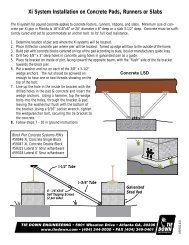
J-BoltBeam ClampBracket<strong>Xi2</strong> Lateral Stabilization with Concrete Footers<strong>Xi2</strong> Pier Placement(1) (1) (1) (1) (1) (1)1-1/2" Tube3rd <strong>System</strong> <strong>for</strong>homes over 80’Lateral Struts(1) (1) (1)1/4"x3/4" 30” Anchorf Tapping w/vertical Screwsstrapor frame tiew/stabilizer plate(1)(1)(1) (1)1-3/4" Tube(1) (1)(1) (1)Single Section Home0 - 80’(76’ Box) 2 <strong>Xi2</strong> <strong>System</strong>s(1) Over 80’(76’ Box) 3 <strong>Xi2</strong> <strong>System</strong>sDouble Section Home0 - 80’(76’ Box) 2 <strong>Xi2</strong> <strong>System</strong>s(1) Over 80’(76’ Box) 3 <strong>Xi2</strong> <strong>System</strong>sTriple Section Home0 -80’ (76’ Box) 2 <strong>Xi2</strong> <strong>System</strong>s(1) Over 80’ (76’ Box) 3 <strong>Xi2</strong> <strong>System</strong>sNOTE: Diagram represents single section up to 16’ width, Xi Xidouble section up to 32’ width, and triple section homes up to 48’width. Single section homes have an “overturning <strong>System</strong>moment” 2 2 2 in 3 high 3 34 winds, 4 45 requiring 5 566two 6 anchors per side.24' 24' 24'wide wide wide32' 32' 32' 49' 49' 49' 65' 65' 65' 82' 82' 82' -- -- --28' 28' 28'wide wide30' 30' 30' 46' 46' 46' 62' 62' 62' 76' 76' 76' 80' 80' 80'<strong>Installation</strong> of Lateralwide<strong>System</strong>32' 32' 32'wide-- -- 44' 44' 58' 58' 73' 73' 80' 80'1. Identify the number of systems to be used wide on wide the home-- 44'using58'the73' 80'chart provided.<strong>Xi2</strong>. Identify <strong>System</strong>the 2 location 3 where 4 the 5 lateral 6 systems will be installed.3. Build Xi<strong>System</strong> 24' pier accordingwide 32' 2 49' 3to65' 4State,82' 5Local-- 6or Home Manufacturers guidelines.4. Drill two 3/8”x 3” deep holes in the concrete using holes in galvanizedbracket24'28' wide as 32' 49' 65' 82' --wide 30' a guide. 46' Attach 62' bracket 76' 80' to concrete pad using 3/8”x3-1/2”wedge28'anchors provided. Place nut & washer on anchor, leave enoughroom 32' wide <strong>for</strong> 130' 46' 62' 76' 80'wide-- to 244' threads 58' showing 73' 80' on top of bolt. Using a hammer, tapthe wedge 32' bolts into hole through bracket, leaving nut & washer flushwide-- 44' 58' 73' 80'with bracket. Using a 9/16” socket wrench, tighen wedge/anchor bolt,4 5 6securing bracket to the concrete.5' 82' 5. -- Attach the end of the smaller tube to the bracket mounted on the pad,using the grade 5, 1/2” x 2-1/2” bolt/nut provided.2' 76' 6. 80' Attach the flag end of the larger tube to the opposite I-beam using the“J” bolt over the top of the I-beam with the nut & washer provided.8' 73' 80' (Figure 1 on last page)7. Install a minimum of four (1/4”x3/4’) self-tapping screws into the holesprovided in the lateral strut so that the two tubes are connected together.(Figure 2 on last page)102804,D760
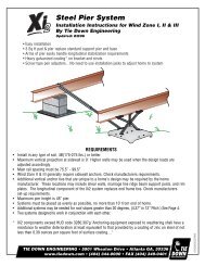
Longitudinal Stabilization <strong>for</strong> <strong>Xi2</strong> <strong>Wind</strong> <strong>Zone</strong> 1When the home manufacturer and/or local requirements include longitudinal stabilization, the installer can usethe LSD system alone, or combine the LSD strut system with the Tie Down’s <strong>Xi2</strong> lateral system.Single SectionUp to 16’ NominalDouble SectionUp to 32’ NominalTriple Sectionup to 48’ NominalWhen LSD struts are used only as longitudinal stabilization, systems must be as evenly spaced as possible, nomore than 16’ from the end of the home.Note: Longitudinal stabilization can be combined economically with the <strong>Xi2</strong> Lateral <strong>System</strong>. Combining LSDstruts with the lateral system saves time and material costs. When combining the lateral and longitudinalsystems, use the placement directions <strong>for</strong> the lateral system.<strong>Xi2</strong> <strong>System</strong> Requirements <strong>for</strong> Roof Pitches Higher than 20 degreesLength of Roof Pitch/Degree of SlopeBuilding 5:12 6:12 7:12 9:1223.6˚ 26.6˚ 30.3˚ 36.9˚34' 2 2 2 236' 2 2 2 238' 2 2 2 340' 2 2 2 342' 2 2 3 344' 2 2 3 346' 2 3 3 348' 2 3 3 350' 3 3 3 352' 3 3 3 354' 3 3 3 356' 3 3 3 3Length of Roof Pitch/Degree of SlopeBuilding 5:12 6:12 7:12 9:1223.6˚ 26.6˚ 30.3˚ 36.9˚58' 3 3 3 360' 3 3 3 362' 3 3 3 364' 3 3 4 466' 3 3 4 468' 3 4 4 470' 3 4 4 472' 3 4 4 474' 4 4 4 576' 4 4 4 578' 4 4 4 580' 4 4 4 5102804,D760