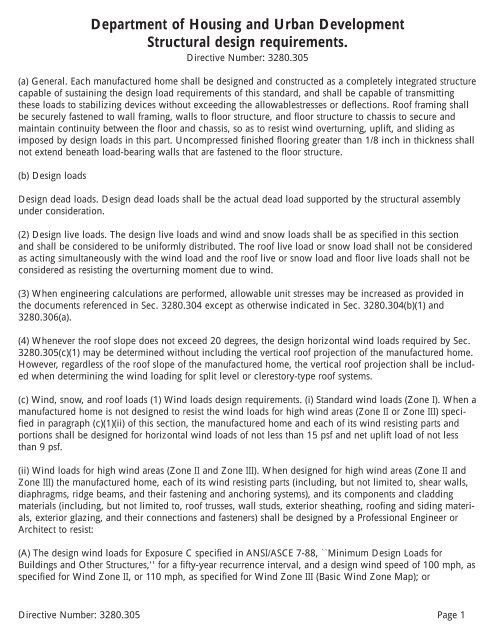
Structural Design Requirements, Directive #3280.305
Structural Design Requirements, Directive #3280.305
Structural Design Requirements, Directive #3280.305
- No tags were found...

You also want an ePaper? Increase the reach of your titles
YUMPU automatically turns print PDFs into web optimized ePapers that Google loves.
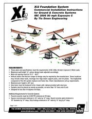
(B) The wind pressures specified in the following table:NOTES:1 The net horizontal drag of 39 PSF to be used in calculating Anchorage for Lateral and Vertical Stability andfor the design of Main Wind Force Resisting Systems is based on a distribution of wind pressures of +0.8 or+24 PSF to the windward wall and -0.5 or -15 PSF to the leeward wall.2 Horizontal drag pressures need not be applied to roof projections when the roof slope does not exceed 20degrees.3 + sign would mean pressures are acting towards or on the structure; - sign means pressures are actingaway from the structure; sign means forces can act in either direction, towards or away from the structure.4 <strong>Design</strong> values in this ``Table'' are only applicable to roof slopes between 10 degrees (nominal 2/12 slope)and 30 degrees.5 The design uplift pressures are the same whether they are applied normal to the surface of the roof or tothe horizontal projection of the roof.6 Shingle roof coverings that are secured with 6 fasteners per shingle through an underlayment which iscemented to a 3/8'' structural rated roof sheathing need not be evaluated for these design wind pressures.7 <strong>Structural</strong> rated roof sheathing that is at least 3/8'' in thickness, installed with the long dimension perpendicularto roof framing supports, and secured with fasteners at 4'' on center within 3'-0'' of each gable endor endwall if no overhang is provided and 6'' on center in all other areas, need not be evaluated for thesedesign wind pressures.<strong>Directive</strong> Number: 3280.305 Page 2
8 Exterior coverings that are secured at 6'' o.c. to a 3/8'' structural rated sheathing that is fastened to wallframing members at 6'' on center need not be evaluated for these design wind pressures.(2) Wind loads zone designations. The Wind Zone and specific wind design load requirements are determinedby the fastest basic wind speed (mph) within each Zone and the intended location, based on theBasic Wind Zone Map, as follows:(i) Wind Zone I. Wind Zone I consists of those areas on the Basic Wind Zone Map that are not identified inparagraphs (c)(2)(ii) or (iii) of this section as being within Wind Zone II or III, respectively.(ii) Wind Zone II.....100 mph. The following areas are deemed to be within Wind Zone II of the Basic WindZone Map:Local governments: The following local governments listed by State (counties, unless specified otherwise):Alabama: Baldwin and Mobile.Florida: All counties except those identified in paragraph (c)(1)(i)(C) of this section as within Wind Zone III.Georgia: Bryan, Camden, Chatham, Glynn, Liberty, McIntosh.Louisiana: Parishes of Acadia, Allen, Ascension, Assumption, Calcasieu, Cameron, East Baton Rouge, EastFeliciana, Evangeline, Iberia, Iberville, Jefferson Davis, LaFayette, Livingston, Pointe Coupee, St. Helena, St.James, St. John the Baptist, St. Landry, St. Martin, St. Tammany, Tangipahoa, Vermillion, Washington, WestBaton Rouge, and West Feliciana.Maine: Hancock and Washington.Massachusetts: Barnstable, Bristol, Dukes, Nantucket, and Plymouth.Mississippi: George, Hancock, Harrison, Jackson, Pearl River, and Stone.North Carolina: Beaufort, Brunswick, Camden, Chowan, Columbus, Craven, Currituck, Jones, New Hanover,Onslow, Pamlico, Pasquotank, Pender, Perquimans, Tyrrell, and Washington.South Carolina: Beaufort, Berkeley, Charleston, Colleton, Dorchester, Georgetown, Horry, Jasper, andWilliamsburg.Texas: Aransas, Brazoria, Calhoun, Cameron, Chambers, Galveston, Jefferson, Kenedy, Kleberg, Matagorda,Nueces, Orange, Refugio, San Patricio, and Willacy.Virginia: Cities of Chesapeake, Norfolk, Portsmouth, Princess Anne, and Virginia Beach.(iii) Wind Zone III.....110 mph. The following areas are considered to be within Wind Zone III of the BasicWind Zone Map:(A) States and Territories: The entire State of Hawaii, the coastal regions of Alaska (as determined by the 90mph isotach on the ANSI/ASCE 7-88 map), and all of the U.S. Territories of American Samoa, Guam,Northern Mariana Islands, Puerto Rico, Trust Territory of the Pacific Islands, and the United States VirginIslands.<strong>Directive</strong> Number: 3280.305 Page 3
(B) Local governments: The following local governments listed by State (counties, unless specified otherwise):Florida: Broward, Charlotte, Collier, Dade, Franklin, Gulf, Hendry, Lee, Martin, Manatee, Monroe, PalmBeach, Pinellas, and Sarasota.Louisiana: Parishes of Jefferson, La Fourche, Orleans, Plaquemines, St. Bernard, St. Charles, St. Mary, andTerrabonne.North Carolina: Carteret, Dare, and Hyde.(iv) Consideration of local requirements. For areas where local building code requirements exceed thedesign wind speed requirements of these standards, the Department will consider the adoption through rulemakingof the more stringent requirements of the State or local building authority.(3) Snow and roof loads. (i) Flat, curved and pitched roofs shall be designed to resist the following live loads,applied downward on the horizontal projection as appropriate for the design zone marked on the manufacturedhome:Pounds per square foot---------------------------------------------------------------------------------------------------------------------North Zone.................................................. 40Middle Zone................................................. 30South Zone.................................................. 20--------------------------------------------------------------------------------------------------------------------(ii) For exposures in areas (mountainous or other) where snow or wind records or experience indicate significantdifferences from the loads stated above, the Department may establish more stringent requirements forhomes known to be destined for such areas. For snow loads, such requirements are to be based on a roofsnow load of 0.6 of the ground snow load for areas exposed to wind and a roof snow load of 0.8 of theground snow load for sheltered areas.(iii) Eaves and cornices shall be designed for a net uplift pressure of 2.5 times the design uplift wind pressurecited in Sec. 3280.305(c)(1)(i) for Wind Zone I, and for the design pressures cited in Sec. 3280.305(c)(1)(ii)for Wind Zones II and III.(4) Data plate requirements. The Data Plate posted in the manufactured home (see Sec. 3280.5) shall designatethe wind and roof load zones or, if designed for higher loads, the actual design external snow and windloads for which the home has been designed. The Data Plate shall include reproductions of the Load ZoneMaps shown in this paragraph (c)(4), with any related information. The Load Zone Maps shall be not lessthan either 3 1/2 in. by 2 1/4 in., or one-half the size illustrated in the Code of Federal Regulations.ER14JA94.000ER20OC97.004(d) <strong>Design</strong> load deflection. (1) When a structural assembly is subjected to total design live loads, the deflectionfor structural framing members shall not exceed the following (where L equals the clear span betweensupports or two times the length of a cantilever):<strong>Directive</strong> Number: 3280.305 Page 4
Floor L/240Roof and ceiling L/180Headers, beams, and girders (vertical load) L/180Walls and partitions L/180(2) The allowable eave or cornice deflection for uplift is to be measured at the design uplift load of 9 psf forWind Zone I, and at the design uplift pressure cited in paragraph (c)(1)(ii) of this section for Wind Zones IIand III. The allowable deflection shall be (2 x Lc)/180, where Lc is the measured horizontal eave projectionfrom the wall.(e) Fastening of structural systems. (1) Roof framing shall be securely fastened to wall framing, walls to floorstructure, and floor structure to chassis to secure and maintain continuity between the floor and chassis, soas to resist wind overturning, uplift, and sliding as specified in this part.(2) For Wind Zones II and III, roof trusses shall be secured to exterior wall framing members (studs), andexterior wall framing members (studs) shall be secured to floor framing members, with 26 gage minimumsteel strapping or brackets or by a combination of 26 gage minimum steel strapping or brackets and structuralrated wall sheathing that overlaps the roof and floor. Steel strapping or brackets shall be installed at amaximum spacing of 24 on center in Wind Zone II and at a maximum of 16 on center in Wind Zone III. Thenumber and type of fasteners used to secure the steel straps or brackets or structural sheathing shall be capableof transferring all uplift forces between elements being joined.(f) Walls. The walls shall be of sufficient strength to withstand the load requirements as defined in Sec.3280.305(c) of this part, without exceeding the deflections as specified in Sec. 3280.305(d). The connectionsbetween the bearing walls, floor, and roof framework members shall be fabricated in such a manner as toprovide support for the material used to enclose the manufactured home and to provide for transfer of all lateraland vertical loads to the floor and chassis.(1) Except where substantiated by engineering analysis or tests, studs shall not be notched or drilled in themiddle one-third of their length.(2) Interior walls and partitions shall be constructed with structural capacity adequate for the intended purposeand shall be capable of resisting a horizontal load of not less than five pounds per square foot. Anallowable stress increase of 1.33 times the permitted published design values may be used in the design ofwood framed interior partitions. Finish of walls and partitions shall be securely fastened to wall framing.(g) Floors. (1) Floor assemblies shall be designed in accordance with accepted engineering practice standardsto support a minimum uniform live load of 40 lb/ft plus the dead load of the materials. In addition (but notsimultaneously), floors shall be able to support a 200A pound concentrated load on a one-inch diameterdisc at the most critical location with a maximum deflection not to exceed one-eighth inch relative to floorframing. Perimeter wood joists of more than six inches depth shall be stabilized against overturning fromsuperimposed loads as follows: at ends by solid blocking not less than two-inch thickness by full depth ofjoist, or by connecting to a continuous header not less than two-inch thickness and not less than the depthof the joist with connecting devices; at eight-feet maximum intermediate spacing by solid blocking or bywood cross-bridging of not less than one inch by three inches, metal cross-bridging of equal strength, or byother approved methods.(2) Wood, wood fiber or plywood floors or subfloors in kitchens, bathrooms (including toilet compartments),laundry areas, water heater compartments, and any other areas subject to excessive moisture shall be mois-<strong>Directive</strong> Number: 3280.305 Page 5
ture resistant or shall be made moisture resistant by sealing or by an overlay of nonabsorbent materialapplied with water- resistant adhesive. Use of one of the following methods would meet this requirement:(i) Sealing the floor with a water-resistant sealer; or(ii) Installing an overlay of a non-absorbent floor covering material applied with water-resistant adhesive; or(iii) Direct application of a water-resistant sealer to the exposed wood floor area when covered with a nonabsorbentoverlay; or(iv) The use of a non-absorbent floor covering which may be installed without a continuous application of awater- resistant adhesive or sealant when the floor covering meets the following criteria:(A) The covering is a continuous membrane with any seams or patches seam bonded or welded to preservethe continuity of the floor covering; and(B) The floor is protected at all penetrations in these areas by sealing with a compatible water-resistant adhesiveor sealant to prevent moisture from migrating under the nonabsorbent floor covering; and(C) The covering is fastened around the perimeter of the subfloor in accordance with the floor coveringmanufacturer's instructions; and,(D) The covering is designed to be installed to prevent moisture penetration without the use of a water-resistantadhesive or sealer except as required in this paragraph (g). The vertical edges of penetrations for plumbingshall be covered with a moisture-resistant adhesive or sealant. The vertical penetrations located underthe bottom plates of perimeter walls of rooms, areas, or compartments are not required to be sealed; thisdoes not include walls or partitions within the rooms or areas.(3) Carpet or carpet pads shall not be installed under concealed spaces subject to excessive moisture, suchas plumbing fixture spaces, floor areas under installed laundry equipment. Carpet may be installed in laundryspaceprovided:(i) The appliances are not provided;(ii) The conditions of paragraph (g)(2) of this section are followed; and(iii) Instructions are provided to remove carpet when appliances are installed.(4) Except where substantiated by engineering analysis or tests:(i) Notches on the ends of joists shall not exceed one- fourth the joist depth.(ii) Holes bored in joists shall not be within 2 inches of the top or bottom of the joist, and the diameter ofany such hole shall not exceed one-third the depth of the joist.(iii) Notches in the top or bottom of the joists shall not exceed one-sixth the depth and shall not be locatedin the middle third of the span.(5) Bottom board material (with or without patches) shall meet or exceed the level of 48 inch-pounds of<strong>Directive</strong> Number: 3280.305 Page 6
puncture resistance as tested by the Beach Puncture Test in accordance with Standard Test Methods forPuncture and Stiffness of Paperboard, and Corrugated and Solid Fiberboard, ASTM D-1968 (73). The materialshall be suitable for patches and the patch life shall be equivalent to the material life. Patch installationinstruction shall be included in the manufactured home manufacturer's instructions.(h) Roofs. (1) Roofs shall be of sufficient strength to withstand the load requirements as defined in Sec.3280.305 (b) and (c) without exceeding the deflections specified in Sec. 3280.305(d). The connectionsbetween roof framework members and bearing walls shall be fabricated in such a manner to provide for thetransfer of design vertical and horizontal loads to the bearing walls and to resist uplift forces.(2) Roofing membranes shall be of sufficient rigidity to prevent deflection which would permit ponding ofwater or separation of seams due to wind, snow, ice, erection or transportation forces.(3) Cutting of roof framework members for passage of electrical, plumbing or mechanical systems shall notbe allowed except where substantiated by engineering analysis.(4) All roof penetrations for electrical, plumbing or mechanical systems shall be properly flashed and sealed.In addition, where a metal roof membrane is penetrated, a wood backer shall be installed. The backer plateshall be not less than 5/16 inch plywood, with exterior glues, secured to the roof framing system beneath themetal roof, and shall be of a size to assure that all screws securing the flashing are held by the backer plate.(i) Frame construction. The frame shall be capable of transmitting all design loads to stabilizing deviceswithout exceeding the allowable load and deflections of this section. The frame shall also be capable ofwithstanding the effects of transportation shock andvibration without degradation as required by subpart J.(1) Welded connections. (i) All welds shall be made in accordance with the applicable provisions of theSpecification for <strong>Structural</strong> Steel Buildings, Allowable Stress <strong>Design</strong> and Plastic <strong>Design</strong>, AISC, June 1, 1989.The Specification for the <strong>Design</strong> of Cold-Formed Steel <strong>Structural</strong> Members, AISI-1986 with 1989 addendum,and the Stainless Steel Cold-Formed <strong>Structural</strong> <strong>Design</strong> Manual, AISI- 1974.(ii) Regardless of the provisions of any reference standard contained in this subpart, deposits of weld slag orflux shall be required to be removed only from welded joints at the following locations:(A) Drawbar and coupling mechanisms;(B) Main member splices, and(C) Spring hanger to main member connections.(2) Protection of metal frames against corrosion. Metal frames shall be made corrosion resistant or protectedagainst corrosion. Metal frames may be protected against corrosion by painting.[40 FR 58752, Dec. 18, 1975. Redesignated at 44 FR 20679, Apr. 6, 1979, as amended at 44 FR 66195,Nov. 19, 1979; 52 FR 4582, Feb. 12, 1987; 58 FR 55006, Oct. 25, 1993; 59 FR 2469, Jan. 14, 1994; 59 FR15113, 15114, Mar. 31, 1994; 62 FR 54547, Oct. 20, 1997]<strong>Directive</strong> Number: 3280.305 Page 7