143-80 Installation & Maintenance - Sensus
143-80 Installation & Maintenance - Sensus
143-80 Installation & Maintenance - Sensus
- No tags were found...

You also want an ePaper? Increase the reach of your titles
YUMPU automatically turns print PDFs into web optimized ePapers that Google loves.
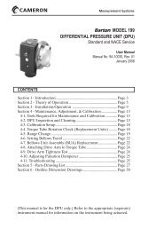
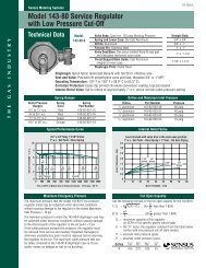
IN-G-REG-1301-1011-01-A*Model <strong>143</strong>-<strong>80</strong> Service Regulator<strong>Installation</strong> and <strong>Maintenance</strong> Instructions1 - Spring Cap11 - Vent2 - Adjustment Ferrule3 - Spring4 - Upper Case10 - Flange Screws12 - Coupling Nut6 - Orifice7 - ValueThe Model <strong>143</strong>-<strong>80</strong> is a general purpose pressureregulator used for natural gas, air, dry CO 2, propane,butane, nitrogen, and other gases. It can be used forgas services to homes, commercial establishmentsand small industries as well as burners, unit heaters,boilers, and other equipment. Model <strong>143</strong>-<strong>80</strong>-1 isa standard regulator, Model <strong>143</strong>-<strong>80</strong>-2 includes aninternal relief valve, and Model <strong>143</strong>-<strong>80</strong>-6 offers lowpressure cut-off.8 - Diaphragm Assembly<strong>Installation</strong> and Start-UpWarning5 - Body9 - Valve StemOnly qualifi ed personnel should install or service a regulator.Regulators should be installed, operated, and maintainedin accordance with applicable codes and regulations, and<strong>Sensus</strong> instructions.If the regulator vents fl uid or a leak develops in the system,it indicates that service is required. Failure to take theregulator out of service immediately may create a hazardouscondition. Personal injury, equipment damage, or leakagedue to escaping fl uid or bursting of pressure-containingparts may result if this regulator is over pressured or isinstalled where service conditions could exceed publishedspecifi cation limits, or where conditions exceed any ratingsof the adjacent piping or piping connections.To avoid such injury or damage, provide pressure-relievingor pressure-limiting devices (as required by the appropriatecode, regulation, or standard) to prevent service conditionsfrom exceeding limits.Additionally, physical damage to the regulator could result inpersonal injury and property damage due to escaping fl uid.To avoid such injury and damage, install the regulator in asafe location.1. Remove the shipping plugs from both the regulator inlet andoutlet connections.2. Make certain that the inside of the piping and the regulatorinlet and outlet connections are free of dirt, pipe dope andother debris.3. Use pipe joint material only on the male threads of the pipebeing connected to the regulator. Do not use pipe jointmaterial on the female threads of the regulator.4. Install the regulator in the piping. Make certain that the gasfl ow through the regulator is in the direction as indicated bythe arrow on the regulator body.The regulators may be installed in any position: right sideup, upside down, vertical piping, diagonal piping, etc., Ifrequired, the diaphragm case may be rotated 360° in anyangle increment. To rotate the <strong>143</strong>-<strong>80</strong> diaphragm case,loosen the coupling nut (12) and reposition the diaphragmcase to the desired position. Retighten the coupling nut to35-50 ft-lbs. (12) to reseal the regulator. Ensure proper sealand verify no leaks by using a soap and water solution orother utility-approved method.The diaphragm case vent (11) should be positioned tominimize the chances of moisture collecting on the vent sideof the diaphragm.The diaphragm case vent must be positioned to protectagainst fl ooding, rain, ice formation, traffi c, tampering, etc.The vent must be protected against nest building animals,bees, insects, etc. to prevent vent blockage and minimize thechances for foreign material from collecting in the vent sideof the regulator diaphragm. If required, the upper diaphragmcase (4) may be rotated by removing the upper-to-lowercase fl ange screws (10) and rotating the upper diaphragmcase to the desired position. Reinstall the diaphragm fl angescrews and tighten to hold the diaphragm case in position,ensuring proper seal and no leaks.CautionDo not overload the diaphragm with a sudden surge of inletpressure. Turn the gas on very slowly. If an outlet stop isused, it should be opened fi rst. Monitor the outlet pressureduring start-up to prevent an outlet pressure overload.5. Turn the gas on very slowly.6. If installing model <strong>143</strong>-<strong>80</strong>-6 Low Pressure Cutoff (LPCO),remove cap (1) and pull up pin located inside spring housingto deactivate LPCO device and initiate fl ow through theregulator.7. Make certain that all connections are tight. Ensure properseal and verify no leaks by using a soap and water solutionor other utility-approved method.8. If needed, adjust outlet pressure (set point) by removing cap(1) and turning adjustment spring button (2). Turn clockwiseto increase and counter-clockwise to decrease outletpressure. Only adjust when gas is fl owing through regulator.Be sure to reinstall cap.*This document replaces RM-1301-R1
Model <strong>143</strong>-<strong>80</strong> Service Regulator<strong>Installation</strong> and <strong>Maintenance</strong> InstructionsCautionIt is the user’s responsibility to assure that all regulator ventsand/or vent lines exhaust to a non-hazardous location awayfrom ANY POTENTIAL sources of ignition. Where vent linesare used, it is the user’s responsibility to assure that eachregulator is individually vented and that common vent linesARE NOT used.9. The vent connection is an escape path for the regulatedgas. Depending upon the type of gas, it could befl ammable as with natural gas and propane. Therefore,the vent connection needs to be located and/or piped sothat potential discharge occurs in a safe area away frombuildings, open fl ames, collection areas, arcing devices, etc.Regulators that are installed indoors or in a non-vented areamust be vented to the outside. Run vent piping from theregulator vent connection to a non-hazardous location onthe outside away from any potential sources of ignition.For regulators equipped with internal relief valves (IRV), Thevent piping must be vent connection size or larger and itslength be as short and direct as possible to a safe area. Thisis to assure the venting of the internal relief valve dischargeto the atmosphere without excessive pressure increase inthe regulator and downstream piping.The outlet of the vent piping must allow for free andunobstructed passage of air and gas and must be protectedagainst the potentials listed in instructions #4, #8 and #9.10. For outdoor installations, it is recommended that theregulator be installed so that the regulator vent facesdownward to avoid the potential for water and other foreignmatter entering the regulator and interfering with the properoperation of the regulator.CautionRegulators are pressure control devices with numerousmoving parts subject to wear that is independent uponparticular operating conditions. To assure continuoussatisfactory operation, a periodic inspection schedule mustbe adhered with the frequency of inspection determined bythe severity of service and applicable laws and regulations.Servicing1. To access valve (7), orifi ce (6), or diaphragm assembly (8),fi rst remove spring compression by unscrewing the springcap (1) and spring adjustment ferrule (2). Remove spring (3)from regulator.2. For access to the valve (7) and orifi ce (6), completely loosenthe coupling nut (12) and remove diaphragm case assemblyfrom body (5).3. To replace valve pad (7), simply pull off of valve stem (9) andreplace with new pad.4. To replace orifi ce (6), unscrew from body using a 1” hexsocket wrench “thin-wall” type. Apply sealant on threads oforifi ce when installing replacement orifi ce. The replacementorifi ce must be installed at 50-60 ft-lbs. of torque.5. To replace diaphragm assembly, remove fl ange screws (10)and disassemble diaphragm assembly. Make certain allparts are reassembled in their correct order and all threadsand joints are tightened evenly and fi rmly.6. Before reassembling body to diaphragm case, make certainthat the O-ring is in position. Ensure proper seal and verifyno leaks by using a soap and water solution or other utilityapprovedmethod.Over Pressurization ProtectionProtection must be provided for the downstream pipingsystem and the regulator’s low pressure chambers to assureagainst the potential for over-pressurization due to a regulatormalfunction or a failure of the regulator to lock up. Theallowable over-pressurization is the lowest of the maximumpressures permitted by federal codes, state codes, or otherapplicable standards. The methods of providing overpressureprotection could be a relief valve, a monitor regulator, a shut-offvalve or similar device.Buried ServiceThe Model <strong>143</strong>-<strong>80</strong> regulator is not recommended for buriedservice.Temperature LimitsThe Model <strong>143</strong>-<strong>80</strong> regulator can be used for the fl owingtemperature of -20°F to 150°F (-28.9°C to 65.5°C).Maximum Emergency PressuresThe maximum pressure to which the regulator inlet may besubjected under abnormal conditions, without causing damageto the regulator, is the stated Maximum Inlet Pressure + 50 psi.The maximum pressure to which the regulators case may besubjected under abnormal conditions without causing damageto the internal parts is: Set point plus 3 psi. If the outlet pressureexceeds this pressure, the regulator must be removed fromservice and carefully inspected. Damaged or otherwiseunsatisfactory parts must be replaced before returning theregulator to service.The maximum outlet pressure that can be safely contained inthe diaphragm case is 10 psi (safely contained means noleakage as well as no bursting.)All products purchased and services performed are subject to <strong>Sensus</strong>’ terms of sale, available at either; http://na.sensus.com/TC/TermsConditions.pdf or 1-<strong>80</strong>0-METER-IT. <strong>Sensus</strong> reserves the right to modify these termsand conditions in its own discretion without notice to the customer.This document is for informational purposes only, and SENSUS MAKES NO EXPRESS WARRANTIES IN THIS DOCUMENT. FURTHERMORE, THERE ARE NO IMPLIED WARRANTIES, INCLUDING WITHOUTLIMITATION, WARRANTIES AS TO FITNESS FOR A PARTICULAR PURPOSE AND MERCHANTABILITY. ANY USE OF THE PRODUCTS THAT IS NOT SPECIFICALLY PERMITTED HEREIN IS PROHIBITED.<strong>80</strong>5 Liberty BoulevardDuBois, PA 15<strong>80</strong>11-<strong>80</strong>0-375-8875For more information, visit us at sensus.com/gas