Model 143-80 Service Regulator with Low Pressure Cut-Off
Model 143-80 Service Regulator with Low Pressure Cut-Off
Model 143-80 Service Regulator with Low Pressure Cut-Off
- No tags were found...

You also want an ePaper? Increase the reach of your titles
YUMPU automatically turns print PDFs into web optimized ePapers that Google loves.
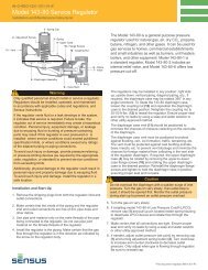
T H E G A S I N D U S T R YSensus Metering Systems<strong>Model</strong> <strong>143</strong>-<strong>80</strong> <strong>Service</strong> <strong>Regulator</strong><strong>with</strong> <strong>Low</strong> <strong>Pressure</strong> <strong>Cut</strong>-<strong>Off</strong>Technical DataSpring Ranges<strong>Model</strong>:<strong>143</strong>-<strong>80</strong>-6Outlet <strong>Pressure</strong> Spring SpringRanges Color Part Number4 1 ⁄2" to 7 1 ⁄2" w.c. Red <strong>143</strong>-62-021-156" to 9 1 ⁄2" w.c. Blue <strong>143</strong>-62-021-167 1 ⁄2" to 15" w.c. Green <strong>143</strong>-62-021-1713 1 ⁄2" to 29" w.c. Orange <strong>143</strong>-62-021-18Valve Body: Cast Iron, 125 psig Working <strong>Pressure</strong>Spring and <strong>Low</strong>er Case: Die-Cast AluminumOrifice: AluminumFulcrum Pin: Stainless SteelValve Seat/Stem: One piece molded Buna-N seat padand fiberglass reinforced nylon stemThroat/Support/Stem Guide: Cast Aluminumintegral to lower caseDiaphragm Plate: Plated SteelOrifice and Maximum Inlet <strong>Pressure</strong>Orifice Part Number <strong>Pressure</strong>1⁄4" aluminum <strong>143</strong>-62-023-49 60 psig5⁄16" aluminum <strong>143</strong>-62-023-51 40 psig3⁄8" aluminum <strong>143</strong>-62-023-52 25 psig7⁄16" aluminum <strong>143</strong>-62-023-53 15 psigTD-1301-LStraight Body3/4" x 3/4"3/4" x 1"1" x 1"1" x 1-1/4"1-1/4" x 1-1/4"Diaphragm: Nylon fabric reinforced Buna-N <strong>with</strong> full 26 in 2 effective areaVent and Valve: Precision-fit polyethylene valve and seat, threaded 3/4" or 1" NPTOperating Temperature: -20° F to 150° F (-28.9° C to 65.5° C)Corrosion Protection: Cases dip primed chromate conversion coating, topcoat enamelInternal Relief Valve: Set to relieve at approximately 7" w.c. above normal outlet pressure settingOUTLET PRESSURE – in w.c.108Typical Performance Curve3/4" x 3/4" Body • 5/16" Orifice7" w.c. Set Point • Blue Spring61psi*41/2 2 5 10 152540psi* psi* psi* psi* psi* psi* psi*2*Inlet <strong>Pressure</strong><strong>Cut</strong>-<strong>Off</strong>00 200 400 600 <strong>80</strong>0 1000 1200 1400 1600 1<strong>80</strong>0 2000Flow in SCFH of Natural Gas (0.6 Specific Gravity – 14.65 psia – 60°F)OUTLET PRESSURE – PSIG3.53.02.52.01.51.00.5Internal Relief ValveLever blocked <strong>with</strong> valve disc in the wide open position7" w.c. Set Point – Blue Spring • 1" Vent – No Vent Piping7/16"Orifice 7/16"Orifice3/8"Orifice00 10 20 30 40 50 60 70 <strong>80</strong>INLET PRESSURE – PSIG5/16"Orifice1/4"OrificeMaximum Emergency <strong>Pressure</strong>The maximum pressure that the model <strong>143</strong>-<strong>80</strong>-6 low pressureregulator inlets may be subjected under abnormal conditions<strong>with</strong>out causing damage to the regulator is the stated MaximumInlet <strong>Pressure</strong> + 10 psiThe maximum pressure to which the <strong>143</strong>-<strong>80</strong>-6 diaphragm case maybe subjected under abnormal conditions <strong>with</strong>out causing damageto the internal parts of the regulator is the set point + 3 psi.If the outlet pressure exceeds this pressure, the regulator mustbe removed from service and carefully inspected. Damaged orotherwise unsatisfactory parts must be replaced before returningthe regulator to service. The maximum outlet pressure that canbe safely contained in the <strong>143</strong>-<strong>80</strong>-6 diaphragm case is 10 psi(safely means no leakage as well as no bursting).Full Open CapacityUse the following formula for the full open capacity for the <strong>143</strong>-<strong>80</strong>-61. Q = K P O (P I –P O ) .... (for P Iless than 1.894)P O2. Q = KP I...................... (for P Igreater than 1.894)2 P OQ = maximum capacity of the regulator(in SCFH of 0.6 specific gravity natural gas).K = the “K” factor, the regulator constant from the table below(orifice <strong>with</strong> low pressure cut-off stem inside).P I = absolute inlet pressure (psia).= absolute outlet pressure (psia).P OOrifice 7⁄16" 3⁄8" 5⁄16" 1⁄4 "K 415 212 125 51
<strong>Model</strong> <strong>143</strong>-<strong>80</strong> <strong>with</strong> <strong>Low</strong> <strong>Pressure</strong> <strong>Cut</strong>-<strong>Off</strong>CapacitiesFlow capacities in SCFH natural gas(0.6 specific gravity – 14.65 psia – 60°F)Note: The last capacity figure in each column indicates the maximumcapacity for each orifice at recommended pressure <strong>with</strong>in the optimumperformance range.The performance data is based on normal testing at 70°Fflowing temperature.Changes in performance can occur at extreme low flowingtemperatures.Other Gases<strong>143</strong>-<strong>80</strong> <strong>Regulator</strong>s are mainly used on natural gas. However, theyperform equally well on LP gas, nitrogen, dry CO2, air and others.Other GasesCorrection FactorAir (Specific Gravity 1.0) 0.77Propane (Specific Gravity 1.53) 0.631350 BTU Propane Air Mix (1.20) 0.71Nitrogen (Specific Gravity 0.97) 0.79Dry Carbon Dioxide (Specific Gravity 1.52) 0.63For other non corrosive gases: 0.6CORRECTION FACTOR =Specific Gravityof the GasOutlet <strong>Pressure</strong>sOutlet <strong>Pressure</strong>sPipe Size Inlet <strong>Pressure</strong> Red Spring 4-1/2" to 7-1/2" w.c.(inches) (psig) Blue Spring 6-1/2" to 9-1/2" w.c.Green Spring 7-1/2" to 15" w.c.Orifice Size (inches)Orifice Size (inches)7/16" 3/8" 5/16" 1/4" 7/16" 3/8" 5/16" 1/4"1/2 240 1<strong>80</strong> 90 140 120 901 400 300 200 100 250 200 160 902 5<strong>80</strong> 420 300 140 370 320 240 1405 <strong>80</strong>0 750 600 230 5<strong>80</strong> 530 460 2203/4" x 3/4" 10 1050 990 740 3<strong>80</strong> 7<strong>80</strong> 720 700 37015 1140 1050 950 460 920 860 <strong>80</strong>0 4<strong>80</strong>25 1100 1100 640 900 1000 66040 1300 870 1300 91060 1160 11601/2 270 210 90 160 120 901 430 310 210 100 260 230 160 902 650 420 300 140 410 350 270 1405 1100 750 610 230 <strong>80</strong>0 730 470 2203/4" x 1" 10 1300 1120 760 3<strong>80</strong> 1220 1090 740 3701" x 1" 20 1300 1300 960 460 1300 1300 930 4<strong>80</strong>25 1300 1300 640 1300 1160 66040 1300 870 1300 91060 1160 11601/2 270 210 90 160 120 901 430 310 210 100 260 230 160 902 650 420 300 140 430 350 270 1405 1100 750 510 230 870 730 470 2201-1/4" x 1-1/4" 10 1300 1120 760 3<strong>80</strong> 1300 1090 740 37020 1300 1300 960 460 1300 1300 930 4<strong>80</strong>25 1300 1300 640 1300 1160 66040 1300 870 1300 91060 1160 1160Dimensions<strong>Regulator</strong> A B C D E F<strong>143</strong>-<strong>80</strong>-6 9 3 ⁄8" 1 5 ⁄8" 3 7 ⁄16" 6 7 ⁄8" 6 7 ⁄16" 1 31 ⁄32"Mounting PositionsCAB6–12 6–9 12–12 12–9E6–6 6–3 12–6 12–3D© Sensus Metering Systems 2008F<strong>80</strong>5 Liberty Boulevard <strong>80</strong>0-375-8875DuBois, PA 15<strong>80</strong>1 Fax: (814) 375-8460www.sensus.com/gasMade in USA02-08-Becken 10M