Barton Chart Recorder Parts Diagram - TRIONICS
Barton Chart Recorder Parts Diagram - TRIONICS
Barton Chart Recorder Parts Diagram - TRIONICS

Create successful ePaper yourself
Turn your PDF publications into a flip-book with our unique Google optimized e-Paper software.
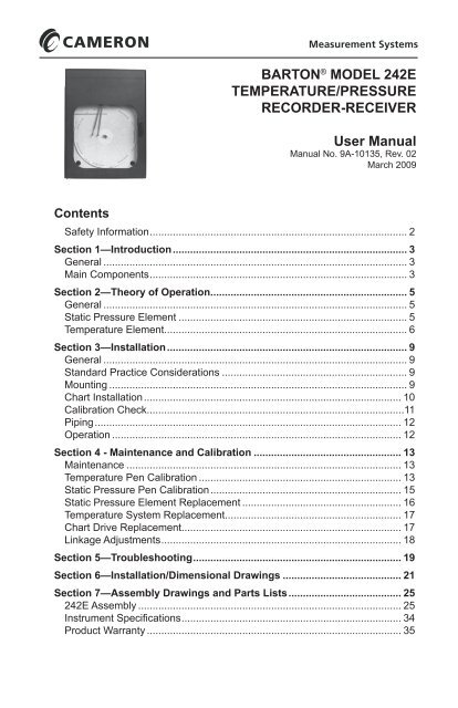
BARTON ® MODEL 242ETEMPERATURE/PRESSURERECORDER-RECEIVERUser ManualManual No. 9A-10135, Rev. 02March 2009ContentsSafety Information......................................................................................... 2Section 1—Introduction.................................................................................. 3General.......................................................................................................... 3Main Components......................................................................................... 3Section 2—Theory of Operation.................................................................... 5General.......................................................................................................... 5Static Pressure Element................................................................................ 5Temperature Element.................................................................................... 6Section 3—Installation................................................................................... 9General.......................................................................................................... 9Standard Practice Considerations................................................................. 9Mounting........................................................................................................ 9<strong>Chart</strong> Installation......................................................................................... 10Calibration Check.........................................................................................11Piping.......................................................................................................... 12Operation..................................................................................................... 12Section 4 - Maintenance and Calibration.................................................... 13Maintenance................................................................................................ 13Temperature Pen Calibration....................................................................... 13Static Pressure Pen Calibration.................................................................. 15Static Pressure Element Replacement........................................................ 16Temperature System Replacement............................................................. 17<strong>Chart</strong> Drive Replacement............................................................................ 17Linkage Adjustments................................................................................... 18Section 5—Troubleshooting........................................................................ 19Section 6—Installation/Dimensional Drawings.......................................... 21Section 7—Assembly Drawings and <strong>Parts</strong> Lists....................................... 25242E Assembly............................................................................................ 25Instrument Specifications............................................................................ 34Product Warranty......................................................................................... 35
Safety InformationBefore installing this instrument, become familiar with the installation instructionsin Section 3.!WARNING: This symbol identifies information about practices or circumstancesthat can lead to personal injury or death, property damage, oreconomic loss.CAUTION:Indicates actions or procedures which if not performed correctlymay lead to personal injury or incorrect function of the instrumentor connected equipment.IMPORTANT: Indicates actions or procedures which may affect instrument operation ormay lead to an instrument response that is not planned.2
242E Temperature/Pressure <strong>Recorder</strong>-Receiver Section 1Section 1—IntroductionGeneralThe <strong>Barton</strong> Model 242E Temperature and Pressure <strong>Recorder</strong>-Receiver is aversatile and rugged instrument designed for general temperature and pressureapplications. It records monitored temperature and pressure on a 12-inchdiameter chart. Up to four elements or bellows-type receiver elements may beused in any combination to operate up to four individual recording pens.Main ComponentsStatic Pressure SystemsThe static pressure system consists of a helical bourdon tube connected tosystem piping. The static pressure element measures the static pressure in apiping system. Elements are available for measuring pressures ranging from30 in. of vacuum (mercury) to 30,000 psi. For a list of elements and ranges,see Table 7.3—Static Pressure Elements on page 31.Thermal SystemsThe thermal systems consist of a spiral bourdon tube, a capillary, and a bulb.All parts are made of stainless steel. The bulb is fitted with a bendable extension,and the capillary is protected with stainless steel armor.Receiver BellowsThe 242E recorder may be connected to a pneumatic transmitter to record the3-15 or 6-30 psi output signal of the transmitter. The instrument may also beconnected to record the output of a pneumatic transmitter simultaneously withthe direct system pressure.Recording MechanismThe recording mechanism is a linkage and pen system that permanently recordsdata. It converts mechanical inputs from the pressure, temperature, andreceiver elements to link lines on a revolving chart. All operative parts of therecorder mechanism are made of stainless steel for a long field life. The penmount is exceptionally rugged. All lines are adjustable. Screw adjustments forzero, range, and linearity assure fast and accurate calibration.3
Section 1242E Temperature/Pressure <strong>Recorder</strong>-Receiver<strong>Chart</strong> DriveA variety of chart drives are available. Both electrical and spring-wound chartdrives fit a wide variety of chart speeds and time intervals that reduce maintenancetime (see Section 5—Troubleshooting on page 19). All chart drives areinterchangeable and fitted with a recorder hub clip that features a simple yetsecure method of locking the chart in place. Explosion-proof electrical chartdrives are available.CaseThe 242E is housed in an aluminum case with a hinged door providing accessfor chart changes and calibration adjustment. The case is finished in a black,polyurethane electrostatic powder paint that is highly resistant to weathering,scratches, marring, and industrial fumes. The Model 242E connects to thesystem or transmitter through fittings in the bottom of the case.4
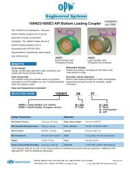
242E Temperature/Pressure <strong>Recorder</strong>-Receiver Section 2Section 2—Theory of OperationGeneralPressure, temperature, and receiver elements in the 242E are connected bytubing or pipe to measure system pressure, system temperature, and transmitteroutput (Figure 2.1).The capillary tubes from the static pressure element and receiver elementconnect directly to the piping system and are filled with the process systemfluid. Two thermal systems are available: a Class V mercury-filled system anda Class I hydrocarbon-filled system. See Instrument Specifications on page 34for details.A chart drive mechanism turns the chart at a selected speed. The chart isdriven by either an electrical motor or a mechanical, spring-wound type motor(see Table 7.2—<strong>Chart</strong> Drives on page 30).Static Pressure ElementThe sensor element consists of a helically coiled bourdon tube with a slightlyflattened cross-section of tubing coiled into a helix or flat spiral. The upperend of the element attaches to a drive arm, and the bottom end of the elementconnects to the capillary tubing, which extends into the bottom of the recordercase and attaches to a connector in the back wall of the case. The connectorallows system piping to be connected externally through the back of the case.Temperature Element(Bourdon Tube)Pressure Element(Bourdon Tube)ReceiverBellowsCapillaryTubingFigure 2.1—242E recorder components5
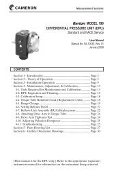
Section 2242E Temperature/Pressure <strong>Recorder</strong>-ReceiverStatic pressure introduced through the tubing into the static pressure elementcauses the element to unwind. Conversely, a reduction of pressure within thetubing causes the element to wind up more tightly. This motion is transmittedthrough the lever arm assembly and its intermediate linkage to the pen shaft,which controls the movement of the recorder pen. The pen transcribes the motiononto a rotating chart to permanently record changes in static pressure.Temperature ElementThe thermal system senses temperature changes, using the thermal expansionpriciple. Temperature changes cause thermal expansion and contraction ofmercury in the bulb. When heated mercury expands, it increases in volume,causing the bourdon tube to exert mechanical force. The bourdon tube movementis transmitted through mechanical linkage to a recording pen (Figure2.2—Temperature element on page 7).Thermal BulbThe thermal bulb acts as the sensing element. Its physical and dimensionalcharacteristics determine response time of the system. Large surface area tovolume, minimum wall thickness, and high heat conductivity are desirable forhigh speed temperature response. The metal used in thermal bulb fabricationshould have a minimum coefficient of expansion and low specific heat factor—stainlesssteel is used in the Model 242E thermal bulb.Capillary TubingThe capillary tubing provides a thermal seal between the temperature bulband bourdon tube. The tubing, fabricated from thick-walled stainless steel,minimizes the internal volume for mercury. The capillary is provided with1/4-inch spiral armor to assure a strong and pliable transmission line betweenthe primary element and the secondary mechanism (bourdon tube).Filling FluidMercury's thermal properties make it highly sensitive to temperature changesand suitable for use with a wide range of temperatures.Secondary MechanismThe measuring element is a precision-wound stainless steel bourdon tube,which converts the volumetric expansion and contraction of the mercury-fillto an angular output of 17 degrees nominal for the full temperature range.6
242E Temperature/Pressure <strong>Recorder</strong>-Receiver Section 2Figure 2.2—Temperature element7
Section 2242E Temperature/Pressure <strong>Recorder</strong>-Receiver8
242E Temperature/Pressure <strong>Recorder</strong>-Receiver Section 3Section 3—InstallationGeneralInspect the instrument as it is removed from packing and report any damagethat may have occurred during shipment.Standard Practice ConsiderationsThe following practices should be observed upon installation:Distances—The distances between the temperature bulb and the recorder caseshould be minimized. Maximum allowable distances are:VA (fully compensated system): 100 feetVB (case compensated system): 20 feetElevation—Maximum elevation of the temperature bulb with respect to therecorder must not exceed 30 feet. The percent of zero shift can be calibratedby the following:Percent Zero Shift = 5 X ± Elevation (feet)Span (Degree Fahrenheit)Process Temperature—The normal operating temperature ranges for Class Vsystems are listed in the Specifications list on page 34. The maximum (momentary)overrange limit is 20% of the total temperature range, while the(momentary) underrange temperature limit of a properly pre-loaded system is-50°F (-45°C).Vibration—Vibration can be minimized by mounting the instrument on asecure support.MountingIMPORTANT: Mount the instrument as level as possible. Limit drill penetration andremove chips. Temperature bulb capillary must precede the recordercase through the panel cutout. Do not apply wrench or bar pressure tothe recorder case, when using a thread mount.Flush or Panel MountingTo use a flush or panel mount, perform the following steps:1. Cut opening in panel to the dimensions shown in Section 6—Installation/Dimensional Drawings.2. Drill out pilot holes located on top and bottom of case. Use aNo. 7 (0.201) drill and 1/4-20 tap as required.9
Section 3242E Temperature/Pressure <strong>Recorder</strong>-Receiver3. Attach two flush mounting brackets to bottom of case using the enclosedself-tapping screws.4. Pass instrument through the panel cutout.5. Attach remaining flush mounting bracket and install panel mountingscrews.Pipe MountingTo mount the recorder to a 2-in. pipe, perform the following steps:1. Place a suitable length of 2-inch pipe into a well-secured floor or wallflange; or if preferred, attach the 2-inch pipe to existing pipe with asaddle that is fitted with a 2-inch pipe.2. Attach the recorder to the pipe, orient the instrument, and tighten retainingscrews.Bulb MountingIMPORTANT: When locating the thermal bulb within a furnace, tank, line, etc., avoiddead spots where fluid circulation is sluggish and temperature is not responsive.Elevation of the temperature bulb, with respect to the recorder,will cause a slight zero shift.To install the temperature element, perform the following steps. Refer toFigure 2.2—Temperature element on page 7 as needed.1. If a thermal well was ordered with the temperature system, thread thethermal well into a 3/4-inch NPT threaded pipeline connection and secureit with a 1-1/8-inch wrench. If the pipeline is already fitted with a thermalwell, proceed to step 2.2. Insert the temperature bulb into the thermal well to its full depths.3. Secure the gland nut into the thermal well or existing 1/2-inch NPT connectionwith a 7/8-inch wrench.4. With the bulb properly installed, secure the packing nut into the glandnut.To compensate for zero shift due to elevation, shift the pen arm linkage of therecorder to realign the pen on the zero line of the chart. See Temperature PenCalibration on page 13 for the adjustment procedure.<strong>Chart</strong> InstallationPerform the following steps to install the chart:1. Open the recorder door.2. Release the chart hub lock (located on the chart drive hub).3. Raise the pen lifter arm.4. Slide the chart between the pen(s) and the chart plate. Insert the chart in10
242E Temperature/Pressure <strong>Recorder</strong>-Receiver Section 3the chart guides in the chart plate, position the hole in the chart over thechart hub. and press the chart onto the hub.5. Lower the pen lifter arm and position the chart to place the pen(s) on thedesired chart time line.6. Secure the chart in place with the chart hub lock.Calibration CheckPressure SystemCheck the calibration of the pressure system prior to placing the recorder intoservice. Refer to the illustration and photo on the next page.1. Connect the recorder to the calibration equipment as shown in Figure 3.1.2. Apply zero pressure (3 or 6 psi for pneumatic transmitter outputpressure recording) and adjust the pen to the zerocircle on thechart using the zero adjust screw.3. Apply 100% pressure. (For example, 100% pressure for an element witha standard range of 0 to 1500 psi is 1500 psi; 50% pressure is 750 psi.)Verify that the pen moves across scale to the 100% pressure indication.4. Apply 50% pressure. Verify that the pen indicates 50% pressure on thechart.5. If the pen does not accurately indicate the pressure being applied, recalibratethe static pressure pen (see Static Pressure Pen Calibration on page15).Figure 3.1—Pressure system calibration11
242E Temperature/Pressure <strong>Recorder</strong>-Receiver Section 45. Remove the mounting screws from the static pressure element and discardthe damaged element.6. Install the new element, using the old mounting screws.7. Connect the tubing to the element at the tubing connection.8. Assemble the lever arm assembly onto the static pressure element shaft;do not tighten the clamp block screw.9. Connect the drive link to the drive arm by engaging the pivot pin andlocking the link tab into place.10. Align the static pressure linkage (range arm, drive link, and drive arm) sothat it lies in the same plane without binding or bending.11. Tighten the clamp block screw.12. Calibrate the static pressure pen in accordance with the procedure outlinedin Static Pressure Pen Calibration on page 15.Temperature System ReplacementTo replace the temperature system, proceed as follows:1. Loosen the packing and gland nuts. Remove the temperature bulb fromthe thermal well.2. Loosen the capillary retaining nut and slip it back on the tubing.3. Remove the four temperature element connection screws located on theback side of the recorder case where the capillary tubing enters the case.4. Remove the union bracket by slipping the bracket onto the capillary connectingtubing. Slip the bracket through the slit provided.5. Remove the intermediate drive arm from the bourdon drive extension.6. Remove the bourdon mounting screws and remove the complete temperatureunit by feeding the capillary through the entry hole provided.7. Install a new element by reversing steps 1 through 6.8. Calibrate the temperature pen in accordance with the procedure outlinedin Temperature Pen Calibration on page 13.<strong>Chart</strong> Drive ReplacementTo replace the chart drive, proceed as follows:1. Release the pressure to the recorder.2. Turn off the chart drive.3. Raise the pen lifter and remove the chart and chart plate.4. Remove the chart drive mounting screws and remove the chart drivefrom the recorder case.5. Position the new chart drive at the back of the recorder case and attachwith mounting screws.6. Replace the chart plate and the chart. Lower the pen to the recordingposition.17
Section 4242E Temperature/Pressure <strong>Recorder</strong>-Receiver7. Disconnect the linkage for the second pen arm from the chart so that thearm moves freely. Make sure the pen follows the timeline on the chart.8. Reattach the linkage and make sure that the second pen arm is on thezero line of the chart.9. Verify calibration.Linkage AdjustmentsFinger-tightening the range arm and drive arm lock screws can leave thescrews too loose; tightening them more than a full turn can break them.To correctly tighten linkage screws, perform the following steps. Refer toFigure 4.2 - Linkage adjustments on page 18 as needed.1. Tighten the lock screw until snug.2. Hold the drive arm at the clamp block by hand or with a 1/4-inch openendwrench. If a wrench is used, place it between the torque tube shaftor bearing. (In the case of the range arm lock screw, place the wrenchbetween the pen shaft and lock screw.)3. Tighten the lock screw 1/3 of a turn to 1/2 of a turn beyond snug.4. Test for tightness by moving the free end of drive arm approximately 1/2inch in either direction. The drive arm should spring back with no yielding.Figure 4.2 - Linkage adjustments18
242E Temperature/Pressure <strong>Recorder</strong>-Receiver Section 5Section 5—TroubleshootingTable 5.1 provides a description of problems, common causes, and recommendedcorrections. For further assistance, contact your local Cameron fieldrepresentative.Table 5.1—Troubleshooting GuideProblem Source Probable Cause Corrective ActionLow or NoIndicationExcessive residueformation on temperaturebulbHeating conductivityof temperature bulb isimpairedRemove fromservice and cleanelementMechanism Loose links or movementsTighten or replaceOut of calibration RecalibrateCorrosion or dirt in Clean or replacemechanismPen arm loose TightenLoss of fillCapillary cracked,kinked, or brokenReplace temperaturebulbElement Defective element Replace elementTubing Loose connection Tighten connectionsTubing plugged Clear tubingPen arm Pen arm bent Straighten orreplace pen armHigh Indication Mechanism Loose links or movementsTighten or replaceOut of calibration RecalibrateErratic Indication Mounting Excessive vibration Secure the means ofmountingMechanism Linkage dragging or Adjust or cleandirtyExcessive pen pressureAdjuston chartNo <strong>Chart</strong> Rotation Fuse Fuse Blown Check and replacefuse<strong>Chart</strong> Drive Electric drive not Turn on chart driveturned onClock motor not Wind chart drivewoundDefective drive Replace driveWrong <strong>Chart</strong> <strong>Chart</strong> Hub Lock Lock not latched Latch hub lockSpeed<strong>Chart</strong> Drive Wrong chart drive Replace with properchart drive19
Section 5242E Temperature/Pressure <strong>Recorder</strong>-Receiver20
242E Temperature/Pressure <strong>Recorder</strong>-Receiver Section 6Section 6—Installation/Dimensional DrawingsFigure 6.1—242E mounting options21
Section 6242E Temperature/Pressure <strong>Recorder</strong>-ReceiverFigure 6.2—242E mounting options (cont'd)22
242E Temperature/Pressure <strong>Recorder</strong>-Receiver Section 6Figure 6.3—Typical thermal well installation23
Section 6242E Temperature/Pressure <strong>Recorder</strong>-Receiver24
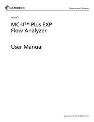
242E Temperature/Pressure <strong>Recorder</strong>-Receiver Section 7Section 7—Assembly Drawings and <strong>Parts</strong> Lists242E AssemblyTable 7.1—242E <strong>Parts</strong> ListItem Description Part No. Per Unit1 Door Assembly, <strong>Recorder</strong>** 9A-0238-1023B 12 Case, <strong>Recorder</strong> 9A-0238-1022C (242E) 13 Pen Lifter Assembly 9A-0238-1159B 14 Latch, Door** 9A-0238-0071C 25 Riser, <strong>Chart</strong> Plate 9A-0238-1210C 46 Screw, FIL. HD., 8-32x3/8 (Not Shown) 9A-0114-1036J 4(Use w/Riser)7 Bushing, Door Stop** 9A-0238-1018C 125
Section 7242E Temperature/Pressure <strong>Recorder</strong>-ReceiverTable 7.1—242E <strong>Parts</strong> ListItem Description Part No. Per Unit8 Screw, CAP 1/4-20x5/8 (Not Shown) 9A-S797-0048Z 4(Used w/Riser)9 Hinge, Door** 9A-0238-1034C 110* Gasket, Connection Static Pressure 9A-0238-0019C 1***11* Gasket, Connection Temperature 9A-0265-0006C 1***(Not Shown)12 Connection, Static Pressure 9A-0238-0046B 1***13 Connection, Temperature (Not Shown) 9A-0265-0003C 1***14 Pen Mount Assembly 1Dual9A-0242-1002B1 Pen (Not Shown) 9A-0242-1001B3 Pen (Pressure)(Not Shown) 9A-0242-1003B3 Pen (Temperature)(Not Shown) 9A-0265-1001B4 Pen (Not Shown) 9A-0242-1004B15* Link Assembly (First or Second Pen) 9A-0238-0015B 1***16* Link Assembly (Third or Fourth Pen; 9A-0262-0004B 1***Not Shown)17 Shaft Assembly, Pen Arm (First from 9A-0238-0006B 1<strong>Chart</strong>)18 Shaft Assembly, Pen Arm (Second from 9A-0238-0007B 1<strong>Chart</strong>)19 Shaft Assembly, Pen Arm (Third from 9A-0238-0008B 1<strong>Chart</strong>; Not Shown)20 Shaft Assembly, Pen Arm (Fourth from 9A-0238-0009B 1<strong>Chart</strong>; Not Shown)21 Pen Shaft Arm Assembly (First or 9A-0202-0034B 1***Second from <strong>Chart</strong>)22 Pen Shaft Arm Assembly (Third from 9A-0242-0003B 1***<strong>Chart</strong>; Not Shown)Pen Shaft Arm Assembly (Fourth from 9A-0265-0001B 1***<strong>Chart</strong>; Not Shown)23* Lever Arm Assembly 9A-0238-0031B 1***24* Pen Arm 9A-BDP-A-2-1 A/R***25* Pen Arm 9A-BDP-A-2-1 A/R***26 Not Used27 Not Used28* Disposable Pen, 1st from <strong>Chart</strong>, 6 perpkgA/R26
242E Temperature/Pressure <strong>Recorder</strong>-Receiver Section 7Table 7.1—242E <strong>Parts</strong> ListItem Description Part No. Per UnitBlue, Scanner, High Temp.Blue Scanner, Low Temp.Black, Scanner, High Temp.Black Scanner, Low TempBlue, Integrator, High Temp.Blue Integrator, Low Temp.Black, Integrator, High Temp.Black Integrator, Low Temp.Blue, Universal, High Temp. ****Blue Universal, Low Temp. ****Black, Universal, High Temp. ****Black Universal, Low Temp. ****9A-BDP-S-1-BL-S-69A-BDP-S-1-BL-L-69A-BDP-S-1-BK-S-69A-BDP-S-1-BK-L-69A-BDP-I-1-BL-S-69A-BDP-I-1-BL-L-69A-BDP-I-1-BK-S-69A-BDP-I-1-BK-L-69A-BDP-U-1-BL-S-69A-BDP-U-1-BL-L-69A-BDP-U-1-BK-S-69A-BDP-U-1-BK-L-6High Temp = +20° to +120° F (-7° to 48°C);Low Temp = -40° to +90° F (-40° to 32° C)29* Disposable Pen, 2nd from <strong>Chart</strong>, 6 perpkgRed, Scanner, High Temp.9A-BDP-S-2-RD-S-6Red Scanner, Low Temp.9A-BDP-S-2-RD-L-6Red, Integrator, High Temp.9A-BDP-I-2-RD-S-6Red Integrator, Low Temp9A-BDP-I-2-RD-L-6Red, Universal, High Temp. ***9A-BDP-U-2-RD-S-6Red Universal, Low Temp ***9A-BDP-U-2-RD-L-6High Temp = +20° to +120° F (-7° to 48°C);Low Temp = -40° to +90° F (-40° to +32°C)30* Disposable Pen, 3nd from <strong>Chart</strong>,6 per pkg (Not shown)Green, Scanner, High Temp.9A-BDP-S-3-GN-S-6Green Scanner, Low Temp.9A-BDP-S-3-GN-L-6Green, Integrator, High Temp.9A-BDP-I-3-GN-S-6Green Integrator, Low Temp.9A-BDP-I-3-GN-L-6Green, Universal, High Temp. **** 9A-BDP-U-3-GN-S-6Green Universal, Low Temp **** 9A-BDP-U-3-GN-L-6High Temp = +20° to +120° F (-7° to 48°C);Low Temp = -40° to +90° F (-40° to 32°C)31* Disposable Pen, 3nd from <strong>Chart</strong>,6 per pkg (Not shown)Purple, Universal, High Temp. **** 9A-BDP-U-4-PL-S-6A/RA/RA/R27
Section 7242E Temperature/Pressure <strong>Recorder</strong>-Receiver28Table 7.1—242E <strong>Parts</strong> ListItem Description Part No. Per UnitPurple Universal, Low Temp. ****9A-BDP-U-4-PL-L-6High Temp = +20° to +120° F (-7° to 48°C);Low Temp = -40° to +90° F (-40° to +32°C)32 Plate, Data <strong>Recorder</strong> 9A-0238-1026G 133 Door Stop Assembly** 9A-0238-1019B 134 Door Latch Assembly Hook** 9A-0238-0029B 135* Gasket, Cover Glass** 9A-0238-0015C 136 Cover, Glass** 9A-0238-0016C 1Cover, Plastic**9A-0238-0182C37 Clip, Cover Glass** 9A-0238-0017C 438 Handle** 9A-0238-1038C 139 Bushing, Door Handle (Not Shown)** 9A-0238-0094C 140 NOT USED41 Pin, Door Handle (Not Shown)** 9A-0003-0022T 142* Gasket, <strong>Recorder</strong> Door** 9A-0096-1003T A/R43 Plate, <strong>Chart</strong> (Not Shown) 9A-0238-0903C 144 Riser, <strong>Chart</strong> Drive 9A-0238-0007C 345* Drive, <strong>Chart</strong> (See Table 7.2) 146* Hub, <strong>Chart</strong> 9A-0238-0033B 147 NOT USED48 Conduit Assembly, Electric <strong>Chart</strong> Drive 9A-0238-0003B 1(Not Shown)49* Gasket, Connection, Electric <strong>Chart</strong> 9A-0238-0019C 1Drive (Not Shown)50 Not Used51 Element, Temperature (See Tables 7.4, 7.5)52 Element, Pressure (See Table 7.3)53 Element, Bellows (Not Shown) Consult Factory54 Riser, Element, Temperature 9A-0265-0005C 255 Not Used56 Screw, Hex. Head, 8-32 x 1/4 (Pen 9A-0116-0014J 2Mount Top Plate)57 Washer, Lock, No. 8 9A-0003-0036K 258 Screw, Round Head, 6-32 x 1/4** 9A-0938-0001J 2659 Screw, Fil. Head, 10-32 x 1/2 9A-0114-0031J 260 Screw, Round Head, 10-32 x 5/16,Element Mounting (Pressure)9A-0111-0085J 2**
242E Temperature/Pressure <strong>Recorder</strong>-Receiver Section 7Table 7.1—242E <strong>Parts</strong> ListItem Description Part No. Per Unit61 Screw, Round Head, 10-32 x 5/16, 9A-0111-0085J 2***Element Mounting (Temperature)62 Screw, Self-tapping, 10-24 x 1/4, Temp. 9A-0946-0002J 4***& Pressure Connections63 Screw, 6-40 x 1/4 9A-0114-0017C 364 Screw, Self-tapping, 10-24 x 1/4** 9A-0946-0002J 265 Screw, Self-tapping, 10-24 x 5/8** 9A-0918-1009J 166 Screw, Round Head, 10-32 x 1/4 9A-0111-0086J 1(Not Shown)67 Screw, Round Head, 10-32 x 5/16 9A-0111-0085J 6(Not Shown)68 Washer, Flat, No. 10 9A-0003-0047K 269 Washer, Shakeproof, No. 10** 9A-0003-0033K 370 Set Screw, Handle, 8-32 x 1/49A-0320-0010J 1(Not Shown)**71 Washer, Flat** 9A-0003-1064K 272 Screw, Self-tapping, Door Stop, 9A-0946-0002J 210-24 x 1/4**73 Screw, Self-tapping, 10-24 x 1/4, 9A-0946-0002J 6Conduit Assembly & Plug, Electric<strong>Chart</strong> Drive (Not Shown)74 Temperature Well Consult Factory A/RScrew, Self-tapping, T23, 1/4-20 Hex 9A-0938-0004J 4(Not Shown)Wrench, Zero Adj 9A-0163-0044C 175 Mounting Bracket Assy., Slip-on(Not Shown)Bracket, Slip-on 9A-0199-1179B 1Screw, Flat Head, 1/4-20 x 1/2 9A-0240-0009J 476 Mounting Bracket Assy., Threaded (Not Shown)Bracket, Threaded 9A-0199-1190B 1Screw, Flat Head, 1/4-20 x 1/2 9A-0240-0009J 477 Mounting Bracket Assy., Panel (Not Shown)Plate, Mounting (Black) 9A-0199-1196C 1Bracket, Panel Mounting 9A-0238-0068C 3Pad, Pressure 9A-0238-0069C 3Panel, Mounting Screw, 5/16-18 9A-0238-0070C 3Screw, 1/4-20 x 5/8 9A-0911-0004J 629
Section 7242E Temperature/Pressure <strong>Recorder</strong>-ReceiverTable 7.1—242E <strong>Parts</strong> ListItem Description Part No. Per UnitNut, Hex., 5/16-18 9A-0500-0033J 6Screw, Flat Head, 1/4-20 x 1/2 9A-0240-0009J 478 Mounting Bracket Assy., Yoke (Not Shown)Bracket, Yoke Mounting 9A-0199-1195B 1Screw, Flat Head, 1/4-20 x 1/2 9A-0240-0009J 4U-Bolt, 2-inch Pipe, 5/16 x 1-1/4, Kit 9A-0440-0001J 1Brace, Mounting Bracket 9A-0224-1049C 1Set Screw, SQ Head, 3/8 - 16 x 5/8 ST 9A-0310-0013J 3(Not Shown)*Recommended Spare <strong>Parts</strong>** 242E only*** Multiply by number of pens used**** Universal type pens are required for (4) four pen metersA/R As RequiredTable 7.2—<strong>Chart</strong> DrivesPart No. Description Model No.Mechanical (Spring Wound)9A-0042-0015T 24 Hour/9 Day 725R0609A-0042-0016T 7 Day 725R0619A-0042-0017T 24 Hour/7 Day 725R0849A-0042-0030 8 Day 725R0679A-0042-0031T 24 Hour/8 Day 725R0689A-0042-1004T 31 Day 725R0709A-0042-1003T 2 Hour/8 Hour 725R0779A-0042-0024T 4 Hour 725R0819A-0042-1007T 1 Hour/15 Minute 725R0869A-0042-0020T 96 Minute/24 Hour 725R1759A-0042-1009T 1 Hour/3 Hour 725R138Battery Driven (1.5 VDC - C Cell Alkaline)9A-0043-1002T 11 Selectable Speeds 820R0019A-0043-1003T11 Selectable Speeds820R007(Foxboro)9A-0043-1004T11 Selectable Speeds820R011(CSA Approved)9A-0043-1005T12 Selectable Speeds820R029(Including 4 Hour)9A-0043-2001T Fast Slow Speeds 830R00130
242E Temperature/Pressure <strong>Recorder</strong>-Receiver Section 7Table 7.2—<strong>Chart</strong> DrivesPart No. Description Model No.<strong>Chart</strong> Drive Accessories9A-0238-0033B One Piece Hub 725G190Hub (Used w/ 625G070)Cap & Chain(Used w/ 725G198)Universal Mounting PlateWind KeyWind Key, Long ShankPush/Pull Hub (Foxboro)725G198625R070620G164725G364725G357725R004Table 7.3—Static Pressure ElementsPart No. Alt. Part No. Standard Range (psi) aHelical Elements (316 SST; 1/8” Union Connection; Ranges in PSIG)9A-B17SL-25 0-259A-B17SL-35 0-359A-B17SL-50 9A0044-0040T 0-509A-B17SL-75 0-759A-B17SL-100 9A-0044-0035T 0-1009A-B17SL-150 9A-0044-0099T 0-1509A-B17SL-200 0-2009A-B17SL-250 9A-0044-0036T 0-2509A-B17SL-300 9A-0044-0044T 0-3009A-B17SL-350 0-3509A-B17SL-400 0-4009A-B17SL-500 9A-0044-0041T 0-5009A-B17SL-600 0-6009A-B17SL-750 9A-0044-0100T 0-7509A-B17SL-1000 9A-0044-0042T 0-10009A-B17SL-1500 9A-0044-0046T 0-15009A-B17SL-2000 0-20009A-B17SL-2500 9A-0044-0048T 0-25009A-B17SL-3000 0-30009A-B17SL-3500 9A-0044-0050T 0-35009A-B17SL-4000 0-40009A-B17SL-5000 9A-0044-0054T 0-500031
Section 7242E Temperature/Pressure <strong>Recorder</strong>-ReceiverTable 7.3—Static Pressure ElementsPart No. Alt. Part No. Standard Range (psi) aHelical Elements (316 SST; 1/8” Union Connection; Ranges in PSIG)9A-B17SL-6000 0-60009A-B17SL-8000 0-80009A-B17SL-10MU 0-10,000Part No.Standard Range (psi) aHigh Pressure (9/16-18 Aminco Process Connection)9A-B17SL-10M0-10,000 (W/18” Welded Connection Line) AutoclaveConn.9A-B17SL-15M0-15,000 (W/18” Welded Connection Line) AutoclaveConn.9A-B17SL-20M0-20,000 (W/18” Welded Connection Line) AutoclaveConn.9A-B17SL-25M0-25,000 (W/18” Welded Connection Line) AutoclaveConn.9A-B17SL-30M0-30,000 (W/18” Welded Connection Line) AutoclaveConn.9A-SS44M-7-4¼”HP x ¼” FNPT High Pressure AdaptorCapsular9A-BCR3-15SL SST: Range (PSI): 3-15Monel9A-B17MK-XXXX“XXXX” = Range in PSIGaUnit can be adjusted to include vacuum measurement.Available in ranges from 0-250 PSIG thru 0-6000 PSIG(W/18” Welded Connection Line) ¼” FNPT Conn.32
242E Temperature/Pressure <strong>Recorder</strong>-Receiver Section 7Table 7.4—Case-Compensated Temperature ElementsClass VB, Mercury Filled,1/8" capillary w/armor, 11/16" diameter sensing bulbTemp (°F) 10 ft (3 m) 15 ft (4.57 m) 20 ft (6 m)0-100 9A-CO-100F10F9A 9A-CO-100F15F9A 9A-CO-100F20F9A0-150 9A-CO-150F10F9A 9A-CO-150F15F9A 9A-CO-150F20F9A0-200 9A-CO-200F10F9A 9A-CO-200F15F9A 9A-CO-200F20F9A0-300 9A-CO-300F10F9A 9A-CO-300F15F9A 9A-CO-300F20F9A0-500 9A-CO-500F10F9A 9A-CO-500F15F9A 9A-CO-500F20F9AClass IB, Hydrocarbon Filled,1/8" capillary w/armor, 3/8" diameter sensing bulbTemp (°F) 10 ft (3 m) 15 ft (4.57 m) 20 ft (6 m)0-100 9A-CO-100F10F7B 9A-CO-100F15F7B 9A-CO-100F20F7B0-150 9A-CO-150F10F7B 9A-CO-150F15F7B 9A-CO-150F20F7B0-200 9A-CO-200F10F7B 9A-CO-200F15F7B 9A-CO-200F20F7B0-300 9A-CO-300F10F7B 9A-CO-300F15F7B 9A-CO-300F20F7B0-500 9A-CO-500F10F7B 9A-CO-500F15F7B 9A-CO-500F20F7BTable 7.5—Fully Compensated Temperature ElementsClass VA, Fully Compensated, Mercury Filled,1/8" capillary w/armor, 11/16" diameter sensing bulbTemp (°F) 20 ft (6 m) 25 ft (7.6 m) 30 ft (9.1 m)0-100 9A-F0-100F20F8A 9A-F0-100F25F8A 9A-F0-100F30F8A0-150 9A-F0-150F20F8A 9A-F0-150F25F8A 9A-F0-150F30F8A0-200 9A-F0-200F20F8A 9A-F0-200F25F8A 9A-F0-200F30F8A0-300 9A-F0-300F20F8A 9A-F0-300F25F8A 9A-F0-300F30F8A0-500 9A-F0-500F20F8A 9A-F0-500F25F8A 9A-F0-500F30F8AClass IA, Fully Compensated, Hydrocarbon Filled,1/8" capillary w/armor, 3/8" diameter sensing bulbTemp (°F) 20 ft (6 m) 25 ft (7.6 m) 30 ft (9.1 m)0-100 9A-F0-100F20F6B 9A-F0-100F25F6B 9A-F0-100F30F6B0-150 9A-F0-150F20F6B 9A-F0-150F25F6B 9A-F0-150F30F6B0-200 9A-F0-200F20F6B 9A-F0-200F25F6B 9A-F0-200F30F6B0-300 9A-F0-300F20F6B 9A-F0-300F25F6B 9A-F0-300F30F6B0-500 9A-F0-500F20F6B 9A-F0-500F25F6B 9A-F0-500F30F6B33
Section 7242E Temperature/Pressure <strong>Recorder</strong>-ReceiverInstrument SpecificationsGeneral:Case (242E) ................................... Die-cast aluminum, black polyurethane electrostaticpowder paint, hinged glass-front door, neoprenegasket seal<strong>Chart</strong> Drive ..................................... Spring-wound or battery-operated<strong>Chart</strong> Size ....................................... 12-inch diameter<strong>Chart</strong> Rotation ................................ 60 minutes to 31 daysNumber of Pens.............................. 1 to 4 (one for each element)Pen Style ........................................ DisposableElement:Type ................................................ Pressure: Helical (bourdon)Output: Bellows (capsule)Temperature: Helical (bourdon), Class Vmercury-filledNumber ........................................... 1 to 4 (any combination)Range ............................................. Bellows: (3-15 or 6-30 psi)Helical: (0-30" Hg vacuum to 0-30,000 psi)Accuracy ......................................... Static Pressure: ±1% of full scaleTemperature: ±1% of full scaleMaterial ........................................... Bellows: Stainless steelHelical: Stainless steel and K-MonelClass V Thermal System (Ambient Temperature Compensated):Class VA ......................................... Fully compensated-40° to 600°F (-40° to 315°C)Class VB ......................................... Case compensated-40° to 600°F (-40° to 315°C)Class I Thermal System: (Ambient Temperature Compensated):Class IA .......................................... Fully compensatedClass IB .......................................... Case compensatedClass I Range Limits:Ethyl-Benzene (EB)........................ -125° to 350°F (-87° to 177°C)Kerosene (KER) ............................. -20° to 500°F (-29° to 260°C)Alcohol (ALC) ................................. -200° to 150°F (-129° to 66°C)34
Product WarrantyA. WarrantyCameron International Corporation ("Cameron") warrants that at the time of shipment, theproducts manufactured by Cameron and sold hereunder will be free from defects in materialand workmanship, and will conform to the specifications furnished by or approved byCameron.B. Warranty Adjustment1. If any defect within this warranty appears, Buyer shall notify Cameron immediately2. Cameron agrees to repair or furnish a replacement for, but not install, any productwhich within one (1) year from the date of shipment by Cameron shall, upon test andexamination by Cameron, prove defective within the above warranty.3. No product will be accepted for return or replacement without the written authorizationof Cameron. Upon such authorization, and in accordance with instructions byCameron, the product will be returned shipping charges prepaid by Buyer. Replacementsmade under this warranty will be shipped prepaid.C. Exclusions from Warranty1. THE FOREGOING WARRANTY IS IN LIEU OF AND EXCLUDES ALL OTHEREXPRESSED OR IMPLIED WARRANTIES OF MERCHANTABILITY, OR FIT-NESS FOR A PARTICULAR PURPOSE, OR OTHERWISE.2. Components manufactured by any supplier other than Cameron shall bear only thewarranty made by the manufacturer of that product, and Cameron assumes no responsibilityfor the performance or reliability of the unit as a whole.3. "In no event shall Cameron be liable for indirect, incidental, or consequential damagesnor shall the liability of Cameron arising in connection with any products soldhereunder (whether such liability arises from a claim based on contract, warranty, tort,or otherwise) exceed the actual amount paid by Buyer to Cameron for the productsdelivered hereunder."4. The warranty does not extend to any product manufactured by Cameron which hasbeen subjected to misuse, neglect, accident, improper installation or to use in violationof instructions furnished by Cameron.5. The warranty does not extend to or apply to any unit which has been repaired or alteredat any place other than at Cameron's factory or service locations by persons notexpressly approved by Cameron.Product Brand<strong>Barton</strong>® is a registered trademark of Cameron International Corporation ("Cameron").35