Barton 199 DPU Manual - Part No. 9A-10030 - Cameron
Barton 199 DPU Manual - Part No. 9A-10030 - Cameron
Barton 199 DPU Manual - Part No. 9A-10030 - Cameron

You also want an ePaper? Increase the reach of your titles
YUMPU automatically turns print PDFs into web optimized ePapers that Google loves.
MODEL <strong>199</strong>DIFFERENTIAL PRESSURE UNIT (<strong>DPU</strong>)Standard and NACE ServiceUser <strong>Manual</strong><strong>Manual</strong> <strong>No</strong>. <strong>9A</strong>-<strong>10030</strong>, Rev. 01January 2008CONTENTSSection 1 - Introduction.................................................................. Page 3Section 2 - Theory of Operation.................................................... Page 5Section 3 - Installation/Operation ................................................. Page 9Section 4 - Maintenance, Adjustment, & Calibration.................. Page 134-1. Tools Required for Maintenance and Calibration............. Page 134-2. <strong>DPU</strong> Inspection and Cleaning............................................. Page 134-3. Calibration Setup.................................................................. Page 184-4. Torque Tube Rotation Check (Replacement Units).......... Page 184-5. Range Change....................................................................... Page 194-6. Setting Bellows Travel........................................................... Page 224-7. Bellows Unit Assembly (BUA) Replacement..................... Page 224-8. Attaching Drive Arm to Torque Tube................................. Page 244-9. Drive Arm Tightness Test..................................................... Page 244-10. Adjusting Pulsation Dampener.......................................... Page 254-11. Troubleshooting................................................................... Page 25Section 5 - <strong>Part</strong>s Drawing/List........................................................ Page 27Section 6 - Outline Dimension Drawings...................................... Page 30(This manual is for the <strong>DPU</strong> only.) Refer to the appropriate (separate)instrument manual for information on the instrument being actuated.
<strong>Barton</strong> instrument is as stated on the back (last
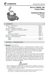
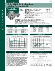
SECTION 1 - INTRODUCTION1-1. GeneralThe <strong>Barton</strong> ® Model <strong>199</strong> Differential Pressure Unit (<strong>DPU</strong>) (see Figure 1 -1) is amechanical device which accurately measures differential pressure relative to agas or liquid flowing through a process system, or to the level of a liquid containedin a process vessel.For process flow measurements, the <strong>DPU</strong> is connected across a primary device(a venturi, an orifice plate or a flow tube) located in the process system.For liquid level measurements, the <strong>DPU</strong> may be connected in a variety of waysto measure the difference in pressure caused by variations in the level of theliquid in the process vessel.1-2. Product DescriptionThe Model <strong>199</strong> <strong>DPU</strong> is a dualHP Housingbellows assembly enclosed withinLP Housingpressure housings. The dualbellows assembly consists of twoopposing internally connected liq-Ventinguid-filled bellows, a center plate,Connectionrange springs, overrange valves, Torque Tubeand a torque tube assembly.ShaftThe pressure housings are connectedby Pipe or tubing to theprimary device located in the sys-PressureConnectionMountingtem piping. Variations in differen-Brackettial pressure within the pressurehousings cause the bellows to expand or contract in a linear direction towardsthe side having the lowest pressure.The linear movement of the bellows is converted into angular rotation whentransmitted to the torque tube shaft by the drive arm and this mechanical motionactuates the mechanism of the process monitoring instrument.The process monitoring instrument that is connected to the torque tube assemblymay be an indicator, a switch, a transmitter, a recorder, or other processcontrol device.1-3. SpecificationsTorque Tube Rotation (full scale DP).............8° ±10%Torque Tube Material..................................Beryllium Copper (BeCu)Temperature Limits ....................................-40°F/°C to +180°F (+82°C)Maximum <strong>No</strong>n-linearity:0-10" w.c. to 0-400" w.c.(0-25 mbar to 0-993 mbar) .........................±0.5% of full scale withappropriate linkage0-401" w.c. to 0-100 psi(0-996 mbar to 0-6.9 bar) ...........................±0.75% of full scale withappropriate linkageRepeatability ..............................................0.20% of full scale DPHousing Materials/Ranges ..........................Refer to Table 1-13
SWPpsi(bar)Body Housing MaterialTable 1-1. Model <strong>199</strong> <strong>DPU</strong> Material/Range SpecificationsAvailable DP RangesStainless Steel Bellows Inconel Bellows2-1/8" (55mm) O.D. 3-3/4" (95mm) O.D. 2-1/8" (55mm) O.D. 3-3/4" (95mm) O.D.1,000(69)Cast Aluminum 356T6Forged Stainless Steel 316NACE2,000(138)Forged Steel AISI C1018(For NACE Service)2,500(172)3,000(207)Forged Steel AISI C1018Forged Stainless Steel 3160-15 psi to 0-100 psi(0-1 bar to 0-6.9 bar)0-10" w.c. to 0-400" w.c.(0-25 mbar to 0-993 mbar)0-15 psi to 0-100 psi(0-1 bar to 0-6.9 bar)0-10" w.c. to 0-400" w.c.(0-25 mbar to 0-993 mbar)4,500(310)Forged Alloy Steel 41426,000(414)Forged Alloy Steel 4142Forged Stainless Steel 17-4 PHNetVolumein cu. in.(cc)Low Pressure (LP) Head 35" (575 cc) 30" (490 cc) 35" (575 cc) 30" (490 cc)High Pressure (HP) Head 31" (510 cc) 26" (425 cc) 31" (510 cc) 26" (425 cc)Displacement in cu. in.(cc) for full-scaletravel0.5" (8.2 cc) 1.5" (25 cc) 0.5" (8.2 cc) 1.5" (25 cc)NOTES: Zero center or split ranges available on special order (e.g., 0-50" w.c. (0-124 mbar) range may be ordered 25-0-25" w.c. (62-0-62 mbar) or 10-0-40" w.c. (25-0-99 mbar). Intermediate DP ranges available from 0-20" w.c. to 0-100 psi (0-50 mbar ot 0-6.9 bar). Other sizes and types of connectuions(welding stubs, MS, A.N.D., etc.) available upon request. Standard pressure connections are 1/2" (top) and 1/4" (bottom) NPT. Range springs arenot interchangeable between the different size bellows, the inconel bellows, or the 10" w.c. (25 mbar) range. 3,000, 4,500, and 6,000 SWP versionscan be specified to meet NACE MR-01-75 (Rev. 80). Metric conversions are approximate. Outline dimension drawings available upon request.4
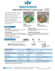
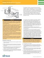
SECTION 2 - THEORY OF OPERATION2-1. Basic Components (See Figure 2-1)Torque Tube Center PlateShaftTorque TubeLP BellowsRange SpringHP BellowsHP OverrangeValveLP HousingTemperatureCompensatorHP HousingLP OverrangeValveHousingBoltsValve StemFigure 2-1. <strong>199</strong> BUA CutawayPulsation DamperDamping Valve PlugA. Pressure HousingsThe two pressure housings of the Model <strong>199</strong> <strong>DPU</strong> are available in the varioussafe working pressure ratings defined in Table 1-1 and in the OutlineDimensional Drawings (seen in Section 6 DRAWINGS).Each pressure housing has two tapped connection ports: one port is locatedin the top of the housing, the other port is located in the bottom of thehousing.The pressure housings may be rotated 180 degrees to facilitate connectionat the top of the housing for draining when used in gas service, or at thebottom to provide venting when used in liquid service.The housings enclose the bellows on each side of the center plate.B. BellowsThe bellows of the Model <strong>199</strong> <strong>DPU</strong> are available in the various materialsand sizes (refer to Table 1-1) to accommodate the various safe workingpressure ratings.The <strong>DPU</strong> has two bellows. One end of each bellows is sealed. The openend of each bellows is attached and sealed to a side of the center plate (onebellows on each side).5
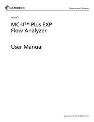
The bellows and center plate are filled with fill liquid via the drive arm holeplug. An opening through the center plate provides a passageway for thetransfer of fill liquid between the two bellows. This opening also allows thebellows to be connected internally by a valve stem.C. Range SpringsThe range of the dual-bellows type <strong>DPU</strong> is determined by the force requiredto move the bellows through their normal range of travel.The range springs, which are available in various ranges (refer toTable 1-1), act with the bellows and torque tube to balance the differentialpressure applied to the unit. The number of springs used and their springrate depends on the individual differential pressure range requirement.Drive ArmHole Plug(DO NOT LOOSEN)Torque Tube Gland Nut(DO NOT LOOSEN)RetainerScrewsRangeSpringAssemblyTorqueTubeShaftLockRangeNutSprings2-1/8" Bellows Unit Assembly (BUA)PushRodDrive ArmHole Plug(DO NOT LOOSEN)Torque Tube Gland Nut(DO NOT LOOSEN)Spring PostRange SpringAssemblyRetainer NutTorqueTubeShaftRangePush RodLockSprings Spring NutEnd Cup3-3/4" Bellows Unit Assembly (BUA)Figure 2-2. Bellows Unit Assemblies (BUAs)6
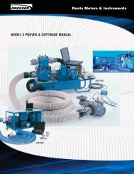
D. Torque Tube AssemblyCenter PlateO-Ring SealTorque TubeLock NutTorque TubeTorque TubeShaft8°RotationWeldBall BearingNeedle BeaingWeldDrive ArmValve StemDisc0.200"Bellows TravelMinaturePrecisionBall BearingValve StemFigure 2-3. Torque Tube AssemblyAs illustrated in Figure 2-3, the torque tube assembly consists of a torquetube, a torque tube shaft, and the supporting members. The outboard endof the torque tube shaft is attached to the center plate. The torque tubeshaft, located in the center of the torque tube, is welded to the inboard endof the tube.Movement of the bellows is transmitted by the drive arm to the torque tubeas a rotary motion. Since the torque tube is attached to the center plate,the tube must twist when subjected to torque. The torque tube shaft, whichis freely supported within the torque tube at its outer end, but connectedto the torque tube and drive arm at its inner end, rotates through the sameangle as the differential pressure unit.NOTE: An extended torque tube is used on electronic transmitters andexplosion-proof instruments.E. Pulsation DampenerThe pulsation dampener (see Figure 2-1) controls the flow of fill-liquidbetween the high and low-pressure bellows with an externally adjustablepulsation dampener needle valve. Restriction of liquid flow reduces theeffects of pulsation. In applications where pulsation is not a problem, theneedle valve is set to the fullopen position.7
8(Blank Page)
SECTION 3 - INSTALLATION/OPERATION3-1. UnpackingThe <strong>199</strong> <strong>DPU</strong> should be inspected at time of unpacking to detect any damagethat may have occurred during shipment.NOTICE: The instrument was checked for accuracy at the factory — do notchange any of the settings during examination or accuracy will be affected.NOTICE: For application in critical media, requiring special cleaning processesand precautions, a polyethylene bag is used to protect the instrumentfrom contamination. This protective bag should be removed only underconditions of controlled extreme cleanliness.NOTICE: Do not locate the instrument near vents or bleed holes that dischargecorrosive vapors or gases.3-2. MountingA. Flush or Panel MountingAttach the case of the instrument (recorder, indicator etc.) to the panel.Refer to the Installation and Operation <strong>Manual</strong> for the specific instrumentfor the mounting details.B. Pipe MountingRefer to the Outline Dimension Drawing in Section 6 for the pipe mountingdiagram. The <strong>DPU</strong> must be mounted approximately level to operateproperly.3-3. Piping — Standard PracticesA. All Applications (flow and liquid level)1 . Shorten the distance between the primary device and the <strong>DPU</strong> asmuch as possible. Distances exceeding 100 feet are not recommended.For distances up to 50 feet, use 1/4-inch or 3/8-inch pipe or tubing.For runs of 50 to 100 feet, use 1/2-inch pipe or tubing. The recommendedlimitation does not apply if an air purge or blow-back system isused.2. Slope all piping at least one inch per linear foot to avoid liquid or gasentrapment.3. Provide two feet of uninsulated piping between the <strong>DPU</strong> and the primarydevice for each 100°F (+37.8°C) in excess of +200°F (+93.3°C).4. Assure that the temperature of the <strong>DPU</strong> never exceeds 180°F(+82°C). When steam tracing is necessary, the steam pressure shouldnot exceed five pounds per square inch and insulation should not beused. If pressure must exceed five pounds per square inch, limit thelength of tubing around the <strong>DPU</strong> to two turns and do not insulate.5. Install a suitable pulsation dampening device upstream of the <strong>DPU</strong>.Where severe pulsation is present, the accuracy of the flow measurementwill be affected.6. Mount the <strong>DPU</strong> on a solid support to minimize vibration. Tighten allpoints, using a suitable compound; leaks in piping can cause measurementerrors.9
3-3. Piping — Standard Practices (Cont.)7. Rotate the housing as necessary to place the connection in the properposition. The <strong>DPU</strong> has connections in the pressure housings to accommodatevarious pipe sizes (refer to Section 6- Drawings).8. Install a valve manifold connecting the <strong>DPU</strong> and the source of differentialpressure to facilitate operation and checking of the <strong>DPU</strong>.9. Locate all shutoff valves and bypass valves to be readily accessible fromthe front of the instrument. Locate block valves at the source of differentialpressure.B. Flow ApplicationsAssure that the <strong>DPU</strong> high-pressure housing is connected to the upstreamtap of the primary device.NOTE: To prevent overheating the <strong>DPU</strong> during blowdown, the operatorshould monitor the temperature by placing his hands on the pipe betweenthe <strong>DPU</strong> and the manifold pipe containing the vent valves.C. Liquid Level ApplicationsThe process media may be used as a reference leg seal fluid when it is of atype that will condense in the reference leg under all conditions.If the process or process media characteristics are such that the above conditionscannot be met, a special reference leg seal fluid will be required. Thespecial seal fluid media characteristics are such that the above conditionscannot be met, a special reference leg seal fluid will be required. The specialseal fluid must not be volatile and must not be miscible with the processmedia. Also, the difference in the densities of the special seal fluid and theprocess media will require compensation in calculating the differential pressurerange of the <strong>DPU</strong>.WARNINGEXPLOSION HAZARD. ORGANIC COMPOUNDS, OIL, GREASE,DIRT, OR SCALE OF ANY KIND CANNOT BE TOLERATED IN ANOXYGEN INSTALLATION.3-4. General Startup Practice ConsiderationsObserve the following practices when starting up an instrument.1. Always start with the block valves closed.2. Perform a zero check on the instrument as follows.NOTICE: For gas service, it is recommended that zero check be performedwith both block valves closed. If the gas flow is pulsating, there may be astanding wave effect in the process line which can displace the indicatorand appear as a zero error.a. Open the bypass valve(s), then open one shutoff valve. This procedureequalizes the pressure between both sides of the instrument. Theinstrument should indicate zero.b. If the instrument does not indicate zero, check for gas or liquid entrapmentin the lines or in the <strong>DPU</strong> (depending on the orientation of thepiping layout and service).10
3-4. General Startup Practice Considerations (Cont.)2. Perform a zero check on the instrument as follows (Cont.)c. If necessary, adjust the pen or pointer by turning the zero adjust on theinstrument.3. Check the manifold and piping for leaks as follows.a. Open the bypass valve(s), then open one shutoff valve to pressurize theinstrument.b. Close the shutoff valve and the bypass valve.c. Any leakage will be indicated by pen or pointer movement, up or downscale.NOTE: Be careful not to subject the <strong>DPU</strong> to unnecessary shock or overrangepressure during operations.11
12(Blank Page)
SECTION 4 - MAINTENANCE, ADJUSTMENT, & CALIBRATION4-1. Tools Required for Maintenance and CalibrationA calibration tool kit (P/N 0202-1005B) containing the necessary tools is availablefrom the factory. The following tools are required for maintenance andcalibration of the <strong>DPU</strong>:Table 4-1. ToolsDescriptionScrewdriverPurposeBracket screws7/16" Hex wrench Housing bolts5/8" Hex wrench Housing bolts3/4" Hex wrench Housing bolt/stud nut (6,000 PSI units)1/8" Allen wrench Dampener Adjustment1/2" Open end wrench Pushrod - bellows cup connection1/2" 12-point socket Housing bolt (6,000 PSI units)Modified Box/Open-ended Wrench(7/16")Kickoff spring lock nut100 ft.-lb. Torque wrench Housing bolts4-2. <strong>DPU</strong> Inspection and CleaningWARNING(High-pressure Gas Installationswith pressures greater than 200 psig)HIGH-PRESSURE GAS HAZARD ON DISASSEMBLY OF THE <strong>DPU</strong>.TO PREVENT POSSIBLE SEVERE PERSONAL INJURY, DEATH,OR SUBSTANTIAL PROPERTY DAMAGE DUE TO THE RELEASEOF INTERNAL PRESSURE, PERFORM THE PRESSURE CHECKPROCEDURE THAT FOLLOWS (Step A) BEFORE REMOVING THE<strong>DPU</strong> HOUSING BOLTS.NOTICEIf accumulation of solids or semi-solids is extensive, remove the housingscarefully to prevent damaging the bellows.WARNING(Housing Bolts)DO NOT REUSE HOUSING BOLTS. IF BOLTS AREDISTURBED, REPLACE WITH NEW BOLTS, PER TABLE 4-2(STANDARD) or TABLES 4-3/4-4 (NACE).REUSE OF HOUSING BOLTS, ESPECIALLY IN CRITICALAPPLICATIONS LIKE HYDROGEN SULFIDE AND SALT WATEREXPOSURES, CAN RESULT IN SEVERE INJURY, DEATHOR SUBSTANTIAL PROPERTY DAMAGE DUE TO BOLTFAILURE.13
Tightentheboltsandreturntheunittothefactoryforrepair.
Table 4-2. Standard Bolt Torque RatingsHousingBoltsSWP Mat'l Mat'l Size Qty <strong>Part</strong> <strong>No</strong>.Lube (<strong>No</strong>te 1)Torque Lb/Ft(<strong>No</strong>te 2)Rotation(<strong>No</strong>te 3)Steel Steel 3/8-16 x 4.5 6 0<strong>199</strong>-1345C Yes 45 180°1000Cres Steel 3/8-16 x 4.5 12 0<strong>199</strong>-1345C Yes 40 270°Alum Steel 3/8-16 x 4.5 6 0<strong>199</strong>-1345C Yes 40 180°2500 Steel Steel 1/2-13 x 5.5 6 0<strong>199</strong>-0085C Yes 95 180°3000 Cres Steel 1/2-13 x 5.5 12 0<strong>199</strong>-0085C Yes 80 180°4500 Steel Steel 1/2-13 x 5.5 12 0<strong>199</strong>-0085C Yes 95 180°Steel1/2-20 x 7 12 0<strong>199</strong>-1001C6000(Stud)Steel1/2-20 24 0<strong>199</strong>-1002CYes 105180°(<strong>No</strong>te 4)(Nut)6000Steel(Bolt)Steel1/2-20 x 6 12 0<strong>199</strong>-1346C1/2-20 12 0<strong>199</strong>-1002CYes 105180°(<strong>No</strong>te 4)(Nut)NOTES:(1) Lubricants: Molykote G paste, Teflon-base pipe dope, graphite-base grease,or similar lubricants. Lube first 2 threads only. Do not lube bearing surface.(2) Torque on bolts is accomplished in 3 or 4 steps. Tighten UNIFORMLY.(3) Rotation of bolt head is measured after bolt is "snug," with approximately5 lb/ft torque. DO NOT EXCEED THIS ROTATION. To tighten bolts withouttorque wrench, use rotation values.(4) Rotation reference for bolt with nut is the sum total of bolt head plus nut, ortotal of 2 nuts.15
Table 4-3. NACE Bolt Torque RatingsSWPItem2000 PSI3000 PSI4500 PSI(13.8 MPa)(20.7 MPa)(31.0 MPa)Fastener12 Pt. Head Bolt12 Pt. Head Boltwith Hex Nut12 Pt. Head Boltwith Hex NutBolt Size 1/2-13 x 5.5" 1/2-20 x 6" 1/2-20 x 6"Bolt Material B7M/L7M Steel B7M/L7M Steel B7M/L7M SteelNut Size N/A 1/2-20 1/2-20Nut Material N/A 4140 Steel 4140 SteelQuantity 6 12 12Bolt <strong>Part</strong> Number 0220-1075J S408-0064Z S408-0064ZNut <strong>Part</strong> Number N/A S408-0021Z S408-0021ZHSG. Gasket 0001-1140R S528-0001Z S528-0001ZHSG. O-RIng 0001-1099R N/A N/ATorque (ft/lbs) 55-60 55-60 55-60SPECIAL NOTES:(1) Lubricants: Molykote G paste, Teflon-base pipe dope, graphite-base grease,or similar lubricants. Lube first 2 threads only. Do not lube bearing surface.(2) Torque on bolts is accomplished in 3 or 4 steps. Tighten UNIFORMLY.(3) If originally supplied with unit, re-install the "Do <strong>No</strong>t Reuse Bolts" and"NACE" product tags.16
Table 4-4. Special 6,000 PSI NACE Bolt Torque Ratings(6,000 PSI NACE Units/Bolts available from Canada Only)SPECIAL NOTES:(1) Lubricants: Molykote G paste, Teflon-base pipe dope, graphite-base grease, orsimilar lubricants. Lube first 2 threads only. Do not lube bearing surface.(2) Torque on bolts is accomplished in 3 or 4 steps. Tighten UNIFORMLY.(3) For DP units marked as 1850 PSI (12.7 MPa) and 1500 PSI (10.3 MPa)originally supplied with 12- point head bolts, <strong>Cameron</strong> has re-rated these lowerpressure <strong>DPU</strong>s to 2000 PSI (13.7 MPa). Apply the parts and use the torquevalues for the 2000 PSI model (Table 4-3).(4) For DP units marked as 1500 PSI (10.3 MPa) originally supplied with 6-pointhead bolts, use a standard B7 alloy steel bolt that is suitable only forapplications where the application environment is not deemed to be sour.WIth the exception of 0<strong>199</strong>-0085C bolts, apply the parts and use the torquevalues for the 2000 PSI model (Table 4-3).(5) If originally supplied with unit, re-install the "Do <strong>No</strong>t Reuse Bolts" and "NACE"product tags.
All NuFlo <strong>Barton</strong> instruments using <strong>199</strong> <strong>DPU</strong> as as actuator are are calibrated at the at the factory. factory.All <strong>DPU</strong>s sold as replacement units or or as as actuators for for other other applications are arechecked for accuracy prior to to shipment.
4-5. Range ChangeChanging the range of the Model <strong>199</strong> <strong>DPU</strong> requires replacing the bellows unitassembly with a unit of the desired range (see para. 4-7 Bellows Unit Assembly(BUA) Replacement).WARNING(High-pressure Gas Installationswith pressures greater than 200 psig)HIGH-PRESSURE GAS HAZARD ON DISASSEMBLY OF THE <strong>DPU</strong>.TO PREVENT POSSIBLE SEVERE PERSONAL INJURY, DEATH,OR SUBSTANTIAL PROPERTY DAMAGE DUE TO THE RELEASEOF INTERNAL PRESSURE, PERFORM THE PRESSURE CHECKPROCEDURE IN PARA. 4-2, Step A BEFORE REMOVING THE<strong>DPU</strong> HOUSING BOLTS.NOTICEIf accumulation of solids or semi-solids is extensive, remove the housingscarefully to prevent damaging the bellows.WARNING(Housing Bolts)DO NOT REUSE HOUSING BOLTS. IF BOLTS AREDISTURBED, REPLACE WITH NEW BOLTS, PER TABLE 4-2(STANDARD) or TABLES 4-3/4-4 (NACE).REUSE OF HOUSING BOLTS, ESPECIALLY IN CRITICALAPPLICATIONS LIKE HYDROGEN SULFIDE AND SALT WATEREXPOSURES, CAN RESULT IN SEVERE INJURY, DEATHOR SUBSTANTIAL PROPERTY DAMAGE DUE TO BOLTFAILURE.NOTICE: The calibration range of the <strong>DPU</strong> was carefully set at the factory. Thefollowing procedure maintains the original factory bellows travel setting whilethe range spring change is performed. This procedure must be strictly followedwhile changing the range spring assembly or altering the adjustment.To replace the range spring assembly with either a new assembly of the samerange or one with a different range value, proceed as follows (this procedure assumesthat the <strong>DPU</strong> is either connected to an indicating instrument or fitted witha scale and pointer to measure torque tube shaft movement):A. 2-1/8-inch Dia. Bellows1. Remove the D PU from service.2. Remove the pressure housing bolts and the low-pressure housing.3. With the pointer at zero, remove the spring retainer screw, retainersprings, and the range spring assembly.NOTE: The pointer will shift from zero. This is a normal action and thepointer should not be readjusted at this point.4. Install the new range spring assembly onto the push rod, and replacethe spring retainer screw.(Continued on next page)19
A. 2-1/8-inch Dia. Bellows (Cont.)5. If the pointer is set above zero, rotate the spring adjustment clockwiseuntil the pointer is set at zero. If the pointer is below zero rotate thespring adjustment conterclockwise until the pointer is set at zero.6. Replace and tighten the lock nut. If the pointer shifts from zero, loosenthe lock nut and reset the pointer as in step 5. Tighten the lock nut.7. Replace the low-pressure housing and install NEW bolts (new gasketsare recommended). Use the torque values listed in Tables 4-2 through4-4. Refer to Housing Bolt WARNING, para. 4-5, page 19.8. Calibrate in accordance with the manual for the actuated instrument.B. 3-3/4-inch Dia. Bellows Without Kickoff Spring (>50" w.c.)1. Remove the instrument from service.2. Remove the pressure housing bolts and the low-pressure housing.3. With the pointer set at zero, remove the lock nut retainer nuts, and therange spring assembly. To remove the range spring assembly, rotatethe assembly counterclockwise while pulling outward on the assembly.NOTE: The pointer will shift from zero. This is a normal action and thepointer should not be readjusted at this point.4. Thread the new assembly onto the push rod, and align the holes in therange spring assembly with the spring posts. Replace and tighten theretainer nuts.5. Using a spanner wrench, rotate the spring adjustment until the pointeris set at exact zero. Replace and tighten the lock nut. The pointer mustremain at thezerosetting. If the pointer shifts from zero, loosen the locknut and repeat this step.6. Replace the low-pressure housing and bolts (new gaskets are recommended).Use the toque values listed in Tables 4-2 through 4-4. Referto Housing Bolt WARNING, para. 4-5, page 19.7. Calibrate in accordance with the manual for the actuated instrument.C. 3-3/4-inch Dia. Bellows w/Kickoff* Spring (see Figure 4-2)NOTE: The kickoff spring is supplied with the 0-40" w.c. and lower range <strong>DPU</strong>sas standard equipment. It is optional with 0-50" w.c. <strong>DPU</strong>s.*Also referred to as the "anti-stick" spring.1 Remove the instrument from service. Set the pointer (or pen) at zero, usingthe instrument zero adjustment.2. Remove the pressure housing bolts and remove the low-pressure housing.3. With the pointer set at zero, remove the lock nut, four spring retainer nuts,washer and lock nut, and range spring assembly.NOTE: The pointer will shift from zero. This is a normal action and thepointer should not be readjusted at this time.4. Install the range spring assembly, using a 1/2-inch open-ended wrench toconnect the push rod to the low-pressure bellows cup.NOTE: The range spring assembly consists of the range springs, kickoffspring assembly, and the push rod. The assembly is furnished as a completeand assembled unit.20
C. 3-3/4-inch Dia. Bellows w/Kickoff* Spring (Cont.) (see Figure 4-2)5. Position range spring assembly over retainer posts and replace retainer nuts.6. Insert the tubing between the range springs and tighten inboard lock nut.7. Zero the pointer by adjusting the spud on the push rod. Be sure that thekickoff spring is not engaged during this operation.8. Position the kickoff spring to prevent interference with the coil springs andtighten the kickoff spring lock nut. If clearance is needed for the wrenchduring this operation, note the position of the spud (measure with a scaleor count threads to the end of the push rod) and move the spud for therequired clearance. After the lock nut is tightened, return the spud to theoriginal position.Figure 4-2. Kickoff Spring AssemblyNOTE: The lock nut requires a modified 7/16", 12-point box wrench for tightening(Figure 4-3).Figure 4-3. Wrench Modification9. Check the back-clearance between the kickoff spring and the slot. Use awire feeler gage or comparable measuring device. The clearance will varybetween each individual slot but must be at least 0.005-inch for any oneslot to prevent interference with instrument zero. Add or remove washersas required to obtain the proper clearance. Tighten the lock nut securely.10. Install the jam nut and lock the spud to the push rod. Hold with pliers. If thespud was moved in step 9, return the spud to the proper position beforetightening the jam nut.21
C. 3-3/4-inch Dia. Bellows w/Kickoff* Spring (Cont.)11. Apply 100 percent negative pressure to the high-pressure side of the <strong>DPU</strong>and repeat the clearance check and adjustment of step 9.12. Apply 100 percent positive pressure to the high-pressure side of the <strong>DPU</strong>and repeat the clearance check and adjustment of step 9.13. Release all pressure from the instrument and replace the low-pressure housing.Use new gaskets.14. Replace the housing bolts. Use the torque values listed in Tables 4-2through 4-4. Refer to Housing Bolt WARNING, para. 4-2, page 13.4-6. Setting Bellows TravelThe travel of the <strong>DPU</strong> bellows must be adjusted if one of the following occurs.1. The range spring assembly is removed without following the procedure.2. Broken range springs are replaced.3. The indicator pointer has excessive overtravel.4. The indicator pointer has excessive undertravel.To set the bellows travel requires that the <strong>DPU</strong> be attached to the actuatedinstrument and connected to a test pressure source. The procedure for thisadjustment is presented in the manual of the actuated instrument.4-7. Bellows Unit Assembly (BUA) Replacement (See Figure 2-1)WARNING(High-pressure Gas Installationswith pressures greater than 200 psig)HIGH-PRESSURE GAS HAZARD ON DISASSEMBLY OF THE <strong>DPU</strong>.TO PREVENT POSSIBLE SEVERE PERSONAL INJURY, DEATH,OR SUBSTANTIAL PROPERTY DAMAGE DUE TO THE RELEASEOF INTERNAL PRESSURE, PERFORM THE PRESSURE CHECKPROCEDURE IN PARA. 4-2, Step A BEFORE REMOVING THE<strong>DPU</strong> HOUSING BOLTS.NOTICEIf accumulation of solids or semi-solids is extensive, remove the housingscarefully to prevent damaging the bellows.WARNING(Housing Bolts)DO NOT REUSE HOUSING BOLTS. IF BOLTS AREDISTURBED, REPLACE WITH NEW BOLTS, PER TABLE 4-2(STANDARD) or TABLES 4-3/4-4 (NACE).REUSE OF HOUSING BOLTS, ESPECIALLY IN CRITICALAPPLICATIONS LIKE HYDROGEN SULFIDE AND SALT WATEREXPOSURES, CAN RESULT IN SEVERE INJURY, DEATHOR SUBSTANTIAL PROPERTY DAMAGE DUE TO BOLTFAILURE.22
4-7. Bellows Unit Assembly (BUA) Replacement (Cont.) (See Figure 2-1)COMPONENT REMOVAL NOTICE: See (separate) actuated instrument<strong>Manual</strong> for particular components that must be removed to gain access to <strong>DPU</strong>case mounting screws. Support <strong>DPU</strong> during disassembly. Do not loosen drivearm hold plug (located in the top of the BUA center plate) when removingmounting bracket. If plug is loosened, bellows fill fluid will be lost.NOTE: The reference designations listed relate to <strong>Part</strong>s Drawing in Section 5.1. Disconnect the <strong>DPU</strong> piping and remove the instrument from service.2. Loosen the actuated instrument drive arm and slide off of the torque tubeshaft. Do not disconnect the instrument linkage.3. Remove the four case-retaining screws and remove the case assembly.4. (Indicators only) Remove the three pipe mounting adapter bracket screws(10, 11) and remove the adapter bracket (13).5. Remove the three mounting bracket screws and remove the case mountingbracket (18).6. Remove the pressure housings bolts and pressure housings (26).7. Place the pressure housings (26) on the replacement bellows unit assembly(1) and insert and start (only) the pressure housing bolts.8. Attach the case mounting bracket (18) to the replacement assembly, usingthree mounting bracket screws.9. (Indicators only) Attach the pipe mounting adapter bracket (13) using threescrews.10. Support the <strong>DPU</strong> and tighten and torque the pressure housing bolts to thespecifications listed in Tables 4-2 through 4-4. Refer to Housing BoltWARNING, para. 4-7, page 22.11. Attach the case assembly using four case retaining screws.12. Attach drive arm and linkage.13. Tighten drive arm to torque tube, per para. 4-8.14. Replace any instrument components that were removed (refer to theCOMPONENT REMOVAL NOTICE above).15. Calibrate the instrument before returning it to service.23
4-8. Attaching Drive Arm to Torque TubeFigure 4-4. Drive Arm to Torque Tube Connection1. Slip drive arm over torque tube shaft; clear end of torque tube housing byapproximately 0.030 inches before securing to prevent interference.2. To tighten the drive arm assembly onto the torque tube shaft:a. Supporting block and shaft, tighten clamp screw until snug to shaft.b. Still supporting block/shaft, tighten clamp screw an additional:• Sintered: 1/3 to 1/2 turn (screw can normally turn one full revolutionbefore breaking.)• Slotted: 1/4 to 1/3 turn (slot in the slotted clamp block should stillbe open.)NOTICE: For Nuclear, Seismic, and High Shock Qualified Units, perform DriveArm Tightness Test, per para. 4-9.4-9. Drive Arm Tightness Test(Nuclear, Seismic, and High Shock Qualified Units Only)This procedure tests the drive arm to torque tube attachment for tightness, byapplying torque developed by the <strong>DPU</strong> onto a fixed drive arm. Care should betaken to apply pressure slowly, as torque is being applied to the connectionthrough the torque tube drive shaft and not the torque tube itself.With pointer at normal 0% torque tube rotation position (max. minimum scaleposition or 0% on a normal 0 to 100% scale unit), adjust drive arm stop bracket(or use alternate means) to prevent pointer from moving (stop bracket interferreswith drive arm movement). <strong>No</strong>te: On reverse acting/split range units, it will benecessary to pressurize <strong>DPU</strong> to move pointer to max. minimum scale position,and on suppressed units, it will be necessary to apply pressure to establish areference point to check for "zero" shift.Pressurize <strong>DPU</strong> as required to full calibrated scale differential pressure (100% ofthe full scale range). This achieves 8-degrees of torque tube drive shaft equivalenttorque onto the connection.Observe shift in the unit "zero" following <strong>DPU</strong> depressurization (as required) anddrive arm stop bracket readjusting (to allow free movement of drive arm andpointer). A downscale (counter-clockwise) shift in "zero" of greater than 1/2% isindicative of drive arm slippage necessitating further clamp block tightening.24
4-10. Adjusting Pulsation Dampener (See Figure 2-1)1. Remove dust cover and insert 1/8 hex key into needle valve.2. Turn valve clockwise to closed position, approx. 3 turns.3. Back out valve 1/2 turn or as required to reduce pulsations/shock pressures.4-11. TroubleshootingSee Table 4-5 and refer to actuated instrument <strong>Manual</strong> for more information.Table 4-5. Troubleshooting ChartTrouble* Possible Source Probable Cause Corrective ActionLow or <strong>No</strong> Primary Element Orifice installed backwards Replace orificeIndication or Differential or oversizedPressure SourceFlow blocked upstream Clean out run orfrom runopen valveLoss of liquid in referenceleg (liquid level)Density changes in processmedia or reference legRefill reference legRefill reference legwith same densityliquid as processmediaPiping from Pressure tap holes plugged Clean out pipingPrimary Elementto <strong>DPU</strong>Bypass valve open orleakingLiquids or gases trappedin pipingOpen block or shut-off valvesBlock or shutoff valvesclosedPiping leaks, HP sideHigh flapper settingClose bypass valve(s)or repair leaksVent pipingRepair leaksAlign drive armre-calibrateBellows Unit Housing(s) filled up with Clean out housing(s)solids, restricting bellowsmovementGas trapped (liquid service)or liquid trapped (gasservice) in housing(s)HP Housing gasket leaks<strong>DPU</strong> tampered withVent housing(s)Replace gasketReturn BUA forrepairMechanism Loose links/movements Tighten or replaceOut of calibrationCorrosion or dirt in mechanismPointer looseCalibrateClean or replaceTighten pointer25
Table 4-5. Troubleshooting Chart (Continued)High Primary Orifice partially restricted Clean out or replaceIndicationor too smallPiping from Leak in LP side piping Repair leaksPrimary Elementto <strong>DPU</strong>Bellows UnitGas trapped (liquid service)in LP housing or liquidtrapped (gas service) in HPhousingLP housing gasket leaksRange spring broken or<strong>DPU</strong> tampered withVent housingReplace gasketReturn BUA forrepairMechanism Loose links or movements Repair or replaceOut of calibrationCalibrateErratic Primary Flow pulsating Install dampeningIndicationdevice upstream of<strong>DPU</strong> runPiping from Liquid trapped in gas Remove (see StartupPrimary Element piping or gas bubble in Procedure-Section 3)to <strong>DPU</strong>liquid pipingVapor generator incorrectly RepipeinstalledSee piping instruc-tionsReference leg gassy orliquid vaporizingBellows Unit Obstructed bellows travel Clean bellowsGas trapped in <strong>DPU</strong> HP or Remove (see StartupLP housing Procedure-Section 3)Mechanism Linkage dragging or dirty Adjust or cleanPointer dragging on scaleplateAdjust26
SECTION 5 - PARTS DRAWING/LIST5-1. GeneralThe parts list and parts identification drawing(s) for the <strong>DPU</strong> are presented inthe separate <strong>DPU</strong> <strong>Manual</strong>.Figure 5-1. <strong>199</strong> <strong>DPU</strong> <strong>Part</strong>s Drawing27
WARNING(NACE SERVICE)HAZARDOUS GAS AND PRESSURE HAZARD IN NACE QUALIFIEDSERVICE. USE ONLY NACE QUALIFIED REPLACEMENT PARTSFOR HOUSINGS, BOLTS, AND BUA. FOR NACE BOLT PARTNUMBERS, REFER TO TABLES 4-3 & 4-4.ANY DEVIATION FROM USE OF QUALIFIED NACE PARTS INNACE SERVICE WILL VOID THE INSTRUMENT/<strong>DPU</strong> NACERATING(s).Table 5-1. <strong>199</strong> <strong>Part</strong>s ListITEM DESCRIPTION PART NO.PERUNIT1 BELLOWS UNIT ASSEMBLY (BUA) (SPECIFY) 1*2 POST, CALIBRATION SPRING RETAINER(FOR 3-3/4" BELLOWS)0<strong>199</strong>-0019C 43 ROD, SPRING PUSH 0<strong>199</strong>-0049C 1*4 SCREW, RETAINER, 6-32 x 5/16" 0111-0049J 8*5 SPRING ASSEMBLY, CALIBRATION TENSION(FOR 2-1/8" BELLOWS)(SPECIFY) 16 NUT, LOCK - SPRING ADJUST 0<strong>199</strong>-0144C 17 PLUG, PIPE, 1/4" NPT, STEEL 0<strong>199</strong>-0191C 28 PLUG, PIPE, 1/2" NPT, STEEL 0<strong>199</strong>-0192C 29 BOLT, HOUSING (STANDARD UNITS):**STAINLESS STEEL, 1000 PSI UNITSSTEEL, 2500/3000/4500 PSI UNITS0<strong>199</strong>-1345C0<strong>199</strong>-0085CA/RSTUD, ALLOY STEEL, 1/2-20 X 7 FOR 6000PSI UNITS (NOT SHOWN)0<strong>199</strong>-1001CBOLT FOR 6000 PSI UNITS (NOT SHOWN) 0<strong>199</strong>-1346C*10 SCREW, PIPE MOUNT ADAPTER, 3/8-16 X 3/4" 0210-0012J 111 SCREW, SCH CAP, STEEL, 3/8-16 X 1-1/2" LG. 0220-1102J 2*12 SCREW, 3/8-16 X 5/8", STEEL (FOR ITEM 13) 0310-0013J 313 ADAPTER, PIPE MOUNTING 0<strong>199</strong>-0988C 1*14 NUT, SPRING RETAINER, HEX, 6-32,SM PATTERN, SST (FOR 3-3/4" BELLOWS)0500-0028J 8*15 ASSEMBLY, RANGE SPRING1(SPECIFY)(FOR 3-3/4" BELLOWS)16 SPACER, INDICATOR BRACKET 0<strong>199</strong>-0006C 217 SCREW, INDICATOR BRACKET10240-0003J(SOC. FLAT, 3/8-16 X7/8", ST)18 BRACKET (SPECIFY) 119 SCREW, INDICATOR BRACKET, HEX, WASHER20002-1009THD., 3/8 X 1-1/820 SCREW, RECORDER BRACKET, HEX, WASHER10002-0034THD., 3/8-16 X 1/228
Table 5-1. <strong>199</strong> <strong>Part</strong>s List (Continued)ITEM DESCRIPTION PART NO.PERUNIT*21 O-RING, 2-127, NITRILE N3 ** 0001-1178R 1*22 GASKET, TORQUE TUBE 0<strong>199</strong>-0209C 123 NOT USED24 SCREW, RECORDER BRACKET, HEX, WASHER20002-0033THD., 3/8-16 X 5/8*25 GASKET, PRESSURE HOUSING: **1000 PSI ALUMINUM UNITS2500/3000/4500 PSI STEEL UNITS1000/3000/6000 PSI SST & MONEL UNITS0<strong>199</strong>-0027C0<strong>199</strong>-0027C0<strong>199</strong>-0184C26 HOUSING, PRESSURE (SPECIFY) 227 WASHER, LOCK, 3/8"10275-0049C(USED WITH ITEMS 10 AND 11)28 NOT USED29 NUT, 1/2-20, 6000/3000 PSI MONEL UNITSA/R0<strong>199</strong>-1002C(USED WITH ITEM 9)*30 PLUG, DAMPENER VALVE (NOT SHOWN)10<strong>199</strong>-0036CBD HD., 1/4-28 X 1/4, SST31 NOT USED*32 WRENCH, RANGE SPRING ADJUSTMENT 0<strong>199</strong>-0142C 133 KEYS, SET OF HEX (NOT SHOWN) 0016-0013T 1NOTES: * INDICATES RECOMMENDED SPARE PART; A/R INDICATES ASREQUIRED; WHEN ORDERING PARTS, SPECIFY INSTRUMENT SERIAL NUMBER.** FOR NACE SPECIFIC PART NUMBERS, REFER TO TABLES 4-3 AND 4-4.229
SECTION 6 - OUTLINE DIMENSION DRAWINGSFigure 6-1. <strong>199</strong> <strong>DPU</strong> Dimension Drawing (<strong>Part</strong> 1 of 2)30
Figure 6-1. <strong>199</strong> <strong>DPU</strong> Dimension Drawing (<strong>Part</strong> 2 of 2)PRESSURERATINGPSI (MPa)HOUSINGMATERIALTable 6-1. <strong>199</strong> <strong>DPU</strong> DimensionsPRESSURECONNECTIONTOPBOTTOMDIM. AINCHES(mm)DIM. BINCHES(mm)DIM. CINCHES(mm)# BOLTS1,000(6.9)NACE2,000(13.8)2,500(17.2)3,000(20.7)4,500(31.0)6,000(41.4)CAST ALUM. 356T6FORGED ST. AISI C1018(For NACE Service)FORGED ST. AISI C1018FORGED STNL. ST. 316FORGED ALLOY ST. 4142FORGED ALLOY ST. 4142FORGED STNL. ST. 17-4 PHFORGED ALLOY ST. 4142FORGED STNL. ST. 17-4 PH1/2 NPT(<strong>No</strong>te 1)1/2 NPT(<strong>No</strong>te 1)1/2 NPT(<strong>No</strong>te 1)1/2 NPT(<strong>No</strong>te 1)1/2 NPT(<strong>No</strong>te 1)9/16-18UNF(<strong>No</strong>te 2)1/2 NPT(<strong>No</strong>te 1)1/4 NPT(<strong>No</strong>te 1)1/4 NPT(<strong>No</strong>te 1)1/4 NPT(<strong>No</strong>te 1)1/4 NPT(<strong>No</strong>te 1)1/4 NPT(<strong>No</strong>te 1)9/16-18UNF(<strong>No</strong>te 2)1/4 NPT(<strong>No</strong>te 1)6-5/8(168.3)Ø 7(177.8)Ø 7(177.8)Ø 7(177.8)Ø 7(177.8)Ø 7(177.8)Ø 7(177.8)2(50.8)2(50.8)2(50.8)2(50.8)2(50.8)2(50.8)2(50.8)<strong>No</strong>te 1: Can be reversed when ordered or can be rotated 180° in the field.<strong>No</strong>te 2: Suitable for use with Aminko fittings (American Inst. Co., Silver Springs, MD.) or equiv..<strong>No</strong>te 3: All Standard pipe fittings furnished by customer.(Metric conversions are approximate.)2-9/64(54.4)2-9/64(54.4)2-9/64(54.4)2-9/64(54.4)2-9/64(54.4)2(50.8)2-9/64(54.4)6661212121231
Product WarrantyA. Warranty<strong>Cameron</strong> International Corporation ("<strong>Cameron</strong>") warrants that at the time of shipment,the products manufactured by <strong>Cameron</strong> and sold hereunder will be free fromdefects in material and workmanship, and will conform to the specifications furnishedby or approved by <strong>Cameron</strong>.B. Warranty Adjustment(1) If any defect within this warranty appears, Buyer shall notify <strong>Cameron</strong> immediately.(2) <strong>Cameron</strong> agrees to repair or furnish a replacement for, but not install, any productwhich within one (1) year from the date of shipment by <strong>Cameron</strong> shall, upontest and examination by <strong>Cameron</strong>, prove defective within the above warranty.(3) <strong>No</strong> product will be accepted for return or replacement without the writtenauthorization of <strong>Cameron</strong>. Upon such authorization, and in accordance withinstructions by <strong>Cameron</strong>, the product will be returned shipping charges prepaidby Buyer. Replacements made under this warranty will be shipped prepaid.C. Exclusions from Warranty(1) THE FOREGOING WARRANTY IS IN LIEU OF AND EXCLUDES ALL OTHEREXPRESSED OR IMPLIED WARRANTIES OF MERCHANTABILITY, OR FITNESSFORA PARTICULAR PURPOSE, OR OTHERWISE.(2) Components manufactured by any supplier other than <strong>Cameron</strong> shall bear onlythe warranty made by the manufacturer of that product, and <strong>Cameron</strong> assumes noresponsibility for the performance or reliability of the unit as a whole.(3) "In no event shall <strong>Cameron</strong> be liable for indirect, incidental, or consequential damagesnor shall the liability of <strong>Cameron</strong> arising in connection with any products soldhereunder (whether such liability arises from a claim based on contract, warranty, tort,or otherwise) exceed the actual amount paid by Buyer to <strong>Cameron</strong> for the productsdelivered hereunder."(4) The warranty does not extend to any product manufactured by <strong>Cameron</strong> which hasbeen subjected to misuse, neglect, accident, improper installation or to use in violationof instructions furnished by <strong>Cameron</strong>.(5) The warranty does not extend to or apply to any unit which has been repaired oraltered at any place other than at <strong>Cameron</strong>'s factory or service locations by personsnot expressly approved by <strong>Cameron</strong>.Product Brand<strong>Barton</strong>® is a registered trademark of <strong>Cameron</strong> International Corporation("<strong>Cameron</strong>").M E A S U R E M E N T S Y S T E M SFormerly: NuFlo Measurement Systems • <strong>Barton</strong> Instrument Systems • Caldon, Inc.HOUSTONHEAD OFFICE281.582.9500NORTHAMERICA1.800.654.3760ms-us@c-a-m.comASIAPACIFIC+603.2287.1039ms-asiapacific@c-a-m.comEUROPE,MIDDLE EAST& AFRICA+44.1243.826741ms-uk@c-a-m.comU S A • C A N A D A • U K • S C O T L A N D • C H I N A • U A EA L G E R I A • M A L A Y S I A • S I N G A P O R E • w w w . c - a - m . c o m / f l o