NASA Technical Paper 2256 - CAFE Foundation
NASA Technical Paper 2256 - CAFE Foundation
NASA Technical Paper 2256 - CAFE Foundation

Create successful ePaper yourself
Turn your PDF publications into a flip-book with our unique Google optimized e-Paper software.
i,<br />
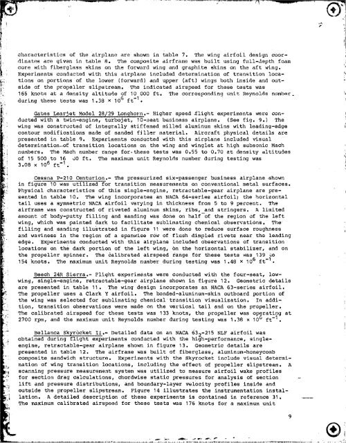
dinates are given in table 8• The composite airframe was built using full-depth foam<br />
characteristics core with fiberglass of theskins airplane on theareforward shownin wingtable and 7• graphite The wing skinsairfoil on thedesign aft wing. coor-<br />
: Experiments conducted with this airplane included determination of transition loca-<br />
l!i!: tions on portions of the lower (£orward) and upper (aft) wings both inside and outside<br />
of the propeller slipstream, The indicated airspeed for these tests was<br />
_ 165 knots at a density altitude of 10 000 ft. The corresponding unit Reynolds number_<br />
i<br />
_•i_ during these tests was 1,38 × 106 ft -I.<br />
i i Gates Learjet Model 28/29 Longhorn.- Higher speed _light experiments were con-<br />
ducted with a twin-engine, turbojet, 10-seat business airplane. (See fig. 9.) The<br />
wing was constructed of integrally Stiffened milled aluminum skins with leading-edge<br />
contour modifications made of sanded filler material• Aircraft physical details are<br />
presented in table 9. Experiments conducted with this airplane included visual<br />
determination-of transition locations on the wing and winglet at high subsonic Mach<br />
numbers. The Mach number range for-these tests was 0•55 to 0.70 at density altitudes i<br />
of 15 500 to 16 00 ft. The maximum unit Reynolds number during testing was f<br />
3.08 x 106 ft -I. i<br />
Cessna P-210 Centurion.- The pressurized six-passenger business airplane shown<br />
in figure 10 was utilized for transition measurements on conventional metal surfaces.<br />
Physical characteristics of this single-engine, retractable-gear airplane are pre-<br />
sented in table 10. The wing incorporates an NACA 64-series airfoil; the horizontal<br />
tail uses a symmetric NACA airfoil varying in thickness from 5 to 9 percent. The<br />
airframe was constructed of riveted aluminum skins, ribs, and stringers• A limited<br />
amount of body-putty filling and sanding was done on half-of the region of the left<br />
wing, which was painted dark to facilitate sublimating chemical observations. The<br />
filling and sanding illustrated in figure 11 were done to reduce surface roughness<br />
and waviness in the region of a spanwise row of flush dimpled rivets near the leading<br />
edge. Experiments conducted with this airplane included observations of transition<br />
locations on the dark portion of the left wing, c)n the horizontal stabilizer, and on<br />
the propeller spinner. The Calibrated airspeed range for these tests was 139 co<br />
154 knots. The maximum unit Reynolds number during testing was I .48 × 106 ft -1 •<br />
Beech 24R Sierra.- Flight experiments were Conducted with the four-seat, low-<br />
wing, single-engine, retractable-gear airplane shown in figure 12. Geometric details<br />
are presented in table 11. The wing design incorporates an NACA 63-series airfoil.<br />
The propeller uses a Clark Y airfoil• The bonded-aluminum-skin outboard portion of<br />
the wing was selected for sublimating chemical _transition visualization. In addi-<br />
tion, transition observations were made on the vertical tail and on the propeller.<br />
_ The calibrated airspeed for these tests was 133 knots, the propeller was operating at<br />
2700 rpm, and the maximum unit Reynolds number during testing was I .38 × I0 u ft-'.<br />
obtain--_ _u_-n_ _ e_eriments conducted with the high-performance, single-<br />
engine, retractable-gear airplane shown in figure 13. Geometric details are<br />
If! Bellanca Skyrocket II•- Detailed data on an NACA 632-215 NLF airfoil was<br />
presented in table 12• The airframe was built of fiberglass, aluminum-honeycomb<br />
composite sandwich structure. Experiments with the Skyrocket include visual determi-<br />
ne, nation of wing transition locations, including the effect of propeller slipstream• A<br />
for section drag calculations, chordwise static pressures for analysis of section<br />
__!ii scanning lift and pressure measurement distributions, system and was boundary-layer utilized to velocity measure airfoil profiles wake insideprofiles and<br />
outside the propeller slipstream. Figure 14 illustrates the instrumentation instal-<br />
I lation A detailed description of these experiments is contained in reference 31<br />
,i I • •<br />
, The maximum calibrated airspeed for these tests was 176 knots for a maximum unit