NASA Technical Paper 2256 - CAFE Foundation
NASA Technical Paper 2256 - CAFE Foundation
NASA Technical Paper 2256 - CAFE Foundation

You also want an ePaper? Increase the reach of your titles
YUMPU automatically turns print PDFs into web optimized ePapers that Google loves.
k!<br />
k<br />
K<br />
, " _Rmlmlllll_lNiiillnp v<br />
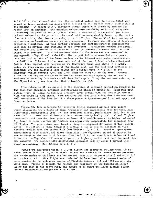
9.0 X 10⁶ at the outboard station. The turbulent wedges seen in fiqure 35(a) were<br />
caused by large chemical particles _ich adhered to the surface during application of<br />
the coating. In figure 35(b), turbulent wedges which were caused by insects are<br />
marked with an asterisk. The unmarked wedges were caused by artificial roughness<br />
(I/4-in-square patch of No. 80 grit). Note the absence of any chemical Particle-<br />
induced wedges in this pattern; this resulted from mechanically loosening the parti-<br />
cles by brushing the chemical coating prior to flight. Figure 35(e) is a summary of<br />
the transition locations acrose the wing semispan. It shows the effects of twist and<br />
propeller slipstream. Airfoil contour accuracy and surface-waviness measurements<br />
were made at several wing stati6ns on the Skyrocket. Deviations between the actual<br />
and theoretical contours as large as 0.117 in. (of excess thickness near the mid-<br />
chord) were measured. Detailed waviness data for the Skyrocket are presented in<br />
the appendix (fig. A5 and table At). The large§t indicated wave height appeared<br />
near the leading edge of the lower surface at the inboard wake probe station where<br />
h _ 0.015 in. This particular wave occurred at the bonded leading-edge attachment<br />
joint. More typical wave heights on the Skyrocket wings were about h = 0.002.<br />
Using the free-stream conditions of the flight test, and the empirical criterion of<br />
reference 27, the allowable wave-height for a single wave (k = 2 in.) on the<br />
Skyrocket varies between 0.017 and 0.015 from the wing tip to the root. However,<br />
since the testing was conducted at low altitudes and high speeds, the allowable<br />
waviness at more typical cruise conditions is larger. Thus, the waviness existing on<br />
the Skyrocket wing was less than that allowable for NLF.<br />
From reference 31, an example of the location of measured transition relative to<br />
the predicted chordwise pressure distribution is shown in figure 36. Predicted tran-<br />
sition (ref. 36) using an integral boundary-layer method with the Granville transi-<br />
tion criterion is also shown. Both measured and predicted transition locations occur<br />
well downstream of the i_cation of minimum pressure (pressure peak) on both upper and<br />
lower surZaces.<br />
Figure 37, from reference 31, presents flight-measured airfoil drag polars,<br />
which illustrate the effects of fixed transition and comparisons with low-turbulence<br />
wind-tunnel measurements (ref. 37) and predicted airfoil performance