NASA Technical Paper 2256 - CAFE Foundation
NASA Technical Paper 2256 - CAFE Foundation
NASA Technical Paper 2256 - CAFE Foundation

You also want an ePaper? Increase the reach of your titles
YUMPU automatically turns print PDFs into web optimized ePapers that Google loves.
i<<br />
1<br />
11<br />
APPENDIX<br />
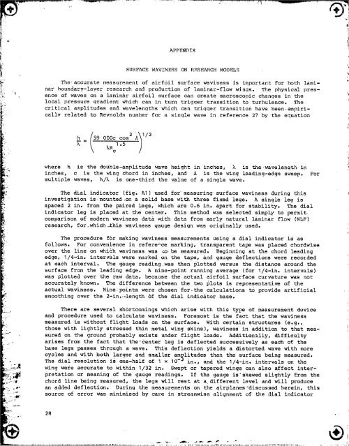
SURFACE WAVINESS ON RESEARCH MODELS<br />
The-accurate measurement of airfoil surface waviness is important for both lami-<br />
nar boundary-layer research and production of laminar-flow wings. The physical pres-<br />
ence of waves on a laminar airfoil surface Can create macroscopic changes in the<br />
local pressure gradient which can in turn trigqer transition to turbulence. The<br />
critical amplitudes and wavelengths which can trigger transition have been empiri t<br />
callv related to Revnolds number for a single wave in reference 27 by the equation<br />
= 9 000c cos<br />
k kRcl.5<br />
where h is the double-amplitude wave height in inches, k is the wavelength in<br />
inches, c is the wing chord in inches, and A is the wing leading-edge sweep.<br />
multiple waves, h/k is one-third the value of a single wave.<br />
The dial indicator (fig. AI) used for measuring surface waviness during this<br />
investigation is mounted on a solid base with three fixed legs. A single leg is<br />
spaced 2 in. from the paired legs, which are 0.6 in. apart for stability. The dial<br />
indicator leg is placed at _le center. This method was selected simply to permit<br />
comparison of modern waviness data with data from early natural laminar flow (NLF)<br />
research, for.which_this waviness gauge design was originally used.<br />
The procedure for making waviness measurements using a dial indicator is as<br />
follows. For convenience in refere-ce marking, transparent tape was placed chordwise<br />
over the line on which waviness was co be measured. Beginning at the chord leading<br />
edge, 1/4-in. intervals were marked on the tape, and gauge deflections were recorded<br />
at each interval. The gauge reading was then plotted versus the distance around the<br />
surface from the leading edge. A nine-point running average (for 1/4-in. intervals)<br />
was plotted over the raw data, because the actual airfoil surface curvature was not<br />
accurately known. The difference between the two plots is representative of the<br />
actual waviness. Nine points were chosen for the calculations to provide artificial<br />
smoothing over the 2-in.-length of the dial indicator base.<br />
There are several shortcomings which arise with this type of measurement device<br />
and procedure used to calculate waviness. Foremost is the fact that the waviness<br />
measured is without flight loads on the surface. With certain structures (e.g.,<br />
those with lightly stressed thin metal wing skins), waviness in addition to that mea-<br />
sured on the ground probably exists under flight loads. Additionally, difficulty<br />
arises from the fact that the-center leg is deflected successively as each of the<br />
base legs passes through a wave. This deflection yields a distorted wave with more<br />
cycles and with both larger and smaller amplitudes than the surface being measured.<br />
The dial resolution is one-half of 1 x 10 -_ in., and the I/4-in. in£ervals on the<br />
wing were accurate to within 1/32 in. Swept or tapered wings can also affect inter-<br />
pretation or meaning of the gauge readings. If the gauge is_skewed slightly from the<br />
chord line being measured, the legs will rest at a different level and will produce<br />
an added deflection. During the measurements on the airplanes-discussed herein, this<br />
source of error was minimized by care in streamwise alignment of the dial indicator<br />
For