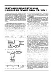
electro-tech.narod.ru, TL594
electro-tech.narod.ru, TL594
electro-tech.narod.ru, TL594
- No tags were found...

You also want an ePaper? Increase the reach of your titles
YUMPU automatically turns print PDFs into web optimized ePapers that Google loves.
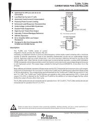
<strong>TL594</strong>Figure 15. Error–Amplifier Sensing TechniquesVrefR1R2VO12To OutputVoltage ofSystem+ErrorAmp–Positive Output VoltageVO = Vref 1 + R 1R233+ErrorAmp –Negative Output VoltageVO = VrefR1R212R1VrefR2VOTo OutputVoltage ofSystemFigure 16. Deadtime Control CircuitFigure 17. Soft–Start CircuitOutputControlOutputQ6RTVref5CTDT4R1R2OutputQVrefDT4RSCS30k0.001Max. % on Time, each output ≈ 45 –801 +R1R2Figure 18. Output Connections for Single–Ended and Push–Pull ConfigurationsOutputControlSingle–EndedQ1C1E1C2QC1.0 mA to500 mA2.4 V ≤ VOC ≤ VrefOutputControlPush–PullQ1C1E1C21.0 mA to 250 mA0 ≤ VOC ≤ 0.4 VQ2E2QEQ2E21.0 mA to 250 mA8 MOTOROLA ANALOG IC DEVICE DATA