RFIC Layout Analysis Using Sonnet EM with ... - Sonnet Software
RFIC Layout Analysis Using Sonnet EM with ... - Sonnet Software
RFIC Layout Analysis Using Sonnet EM with ... - Sonnet Software
- No tags were found...

Create successful ePaper yourself
Turn your PDF publications into a flip-book with our unique Google optimized e-Paper software.
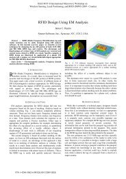
Subsection typeFor <strong>EM</strong> analysis of <strong>RFIC</strong> inductors,<strong>Sonnet</strong>’s new conformal meshingcapability is very useful, because itenables significant memory andsimulation time reductions for curvedand diagonal polygons. Please refer tothe <strong>Sonnet</strong> User's Guide for moreinformation about conformal meshing.You can enable conformal meshing perpolygon, but you can also do Edit>Select All and then change allpolygons at once: Modify > Metalproperties > Fill Type.Add portsOnce the <strong>EM</strong> Project geometry(including vias) is complete andmaterial properties are defined, theremaining step is to define ports. In<strong>Sonnet</strong>, different port types exist, butthe most common port type is the boxwall port. Box walls are well suited forinductor analysis because we can easilyand accurately de-embed the feed lineup to the desired reference plane.Calibration error for box wall ports in<strong>Sonnet</strong> have been shown to exhibitnumerical noise errors than better than100 dB down or more.To define a box wall port, you mustextend each feed line to a box wall.You can do so by adding a newpolygon, or by stretching an existingpolygon. One easy method to stretch:use the Tools > Reshape commandand drag a window around the edgethat you want to stretch. Then, use theModify > Snap to... command tosnap the edge to one of the box walls.To define a box wall port, use theTools > Add Port command and clickon the polygon edge where the feedline touches the box wall. This adds abox wall port at that location, <strong>with</strong> thepositive terminal connected to the feedline and the negative terminalconnected to the box (ground).7