

VOICE OF THE ENGINEER - ElectronicsAndBooks
VOICE OF THE ENGINEER - ElectronicsAndBooks
VOICE OF THE ENGINEER - ElectronicsAndBooks
- No tags were found...

You also want an ePaper? Increase the reach of your titles
YUMPU automatically turns print PDFs into web optimized ePapers that Google loves.
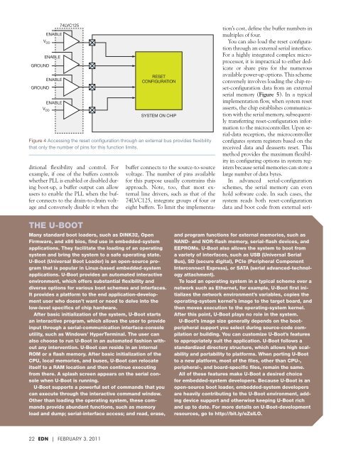
V DDGROUNDGROUNDENABLEENABLEENABLEENABLEV DD74LVC125ditional flexibility and control. Forexample, if one of the buffers controlswhether PLL is enabled or disabled duringboot-up, a buffer output can allowusers to enable the PLL when the bufferconnects to the drain-to-drain voltageand conversely disable it when theRESETCONFIGURATIONSYSTEM ON CHIPFigure 4 Accessing the reset configuration through an external bus provides flexibilitythat only the number of pins for this function limits.buffer connects to the source-to-sourcevoltage. The number of pins availablefor this purpose usually constrains thisapproach. Note, too, that most externalline drivers, such as that of the74LVC125, integrate groups of four oreight buffers. To limit the implementation’scost, define the buffer numbers inmultiples of four.You can also load the reset configurationthrough an external serial interface.For a highly integrated complex microprocessor,it is impractical to either dedicateor share pins for the numerousavailable power-up options. This schemeconversely involves loading the chip-reset-configurationdata from an externalserial memory (Figure 5). In a typicalimplementation flow, when system resetasserts, the chip establishes communicationwith the serial memory, subsequentlytransferring reset-configuration informationto the microcontroller. Upon serial-datareception, the microcontrollerconfigures system registers based on thereceived data and deasserts reset. Thismethod provides the maximum flexibilityin configuring options in system registersbecause serial memories can store alarge number of data bytes.In advanced serial-configurationschemes, the serial memory can evenhold software code. In such cases, thesystem reads both reset-configurationdata and boot code from external seri-<strong>THE</strong> U-BOOTMany standard boot loaders, such as DINK32, OpenFirmware, and x86 bios, find use in embedded-systemapplications. They facilitate the loading of an operatingsystem and bring the system to a safe operating state.U-Boot (Universal Boot Loader) is an open-source programthat is popular in Linux-based embedded-systemapplications. U-Boot provides an automated interactiveenvironment, which offers substantial flexibility anddiverse options for various boot schemes and interfaces.It provides a platform to the end application-developmentuser who doesn’t want or need to delve into thelow-level specifics of chip hardware.After basic initialization of the system, U-Boot startsan interactive program, which allows the user to provideinput through a serial-communication interface-consoleutility, such as Windows’ HyperTerminal. The user canalso choose to run U-Boot in an automated fashion withoutany intervention. U-Boot can reside in an internalROM or a flash memory. After basic initialization of theCPU, local memories, and buses, U-Boot can relocateitself to a RAM location and then continue executingfrom there. A splash screen appears on the serial consolewhen U-Boot is running.U-Boot supports a powerful set of commands that youcan execute through the interactive command window.Other than loading the operating system, these commandsprovide abundant functions, such as memoryload and dump; serial-interface access; and read, erase,and program functions for external memories, such asNAND- and NOR-flash memory, serial-flash devices, andEEPROMs. U-Boot also allows the system to boot froma variety of interfaces, such as USB (Universal SerialBus), SD (secure digital), PCIe (Peripheral ComponentInterconnect Express), or SATA (serial advanced-technologyattachment).To load an operating system in a typical scheme over anetwork such as Ethernet, for example, U-Boot first initializesthe network environment’s variables, copies theoperating-system kernel’s image to the target board, andthen moves execution to the operating-system kernel.After this point, U-Boot plays no role in the system.U-Boot’s image size generally depends on the bootperipheralsupport you select during source-code compilationor building. You can customize U-Boot’s featuresto appropriately suit the application. U-Boot follows astandardized directory structure, which allows high scalabilityand portability to platforms. When porting U-Bootto a new platform, most of the files, other than CPU-,peripheral-, and board-specific files, remain the same.All of these features make U-Boot a desired choicefor embedded-system developers. Because U-Boot is anopen-source boot loader, embedded-system developersare heavily contributing to the U-Boot environment, addingdevice support and otherwise keeping U-Boot richand up to date. For more details on U-Boot-developmentresources, go to http://bit.ly/eZslLO.22 EDN | FEBRUARY 3, 2011


![[270].pdf 37407KB Sep 02 2010 09:55:57 AM - ElectronicsAndBooks](https://img.yumpu.com/50350834/1/185x260/270pdf-37407kb-sep-02-2010-095557-am-electronicsandbooks.jpg?quality=85)
![draaien, A Viruly 1935 OCR c20130324 [320]. - ElectronicsAndBooks](https://img.yumpu.com/49957773/1/190x252/draaien-a-viruly-1935-ocr-c20130324-320-electronicsandbooks.jpg?quality=85)


![20051110 c20051031 [105].pdf 35001KB Feb 18 2009 08:46:32 PM](https://img.yumpu.com/48687202/1/190x253/20051110-c20051031-105pdf-35001kb-feb-18-2009-084632-pm.jpg?quality=85)


