

Closed Loop Speed Controller For OMC506 3-Phase Brushless DC ...
Closed Loop Speed Controller For OMC506 3-Phase Brushless DC ...
Closed Loop Speed Controller For OMC506 3-Phase Brushless DC ...
- No tags were found...

You also want an ePaper? Increase the reach of your titles
YUMPU automatically turns print PDFs into web optimized ePapers that Google loves.
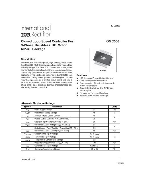
<strong>Closed</strong> <strong>Loop</strong> <strong>Speed</strong> <strong>Controller</strong> <strong>For</strong>3-<strong>Phase</strong> <strong>Brushless</strong> <strong>DC</strong> MotorMP-3T PackageDescription:The <strong>OMC506</strong> is an integrated, high density, three phase<strong>Brushless</strong> <strong>DC</strong> (BL<strong>DC</strong>) motor, speed controller housed in aMP-3Tpackage. The <strong>OMC506</strong> contains the power, driverand control electronics to adjust timing functions and speedcontrol loop parameters to optimize the controller for eachapplication. The electronics contained in the <strong>OMC506</strong> areassembled using mixed process technologies: surfacemount components on a printed circuit board and chip &wire on an Insulated Metal Substrate.This combinationoffers small size, excellent thermal characteristics andelectrically isolated heat sink.PD- 95805<strong>OMC506</strong>MP-3T324810A30306.5V6.510-0.3 to V REFFeatures:n 10A Average <strong>Phase</strong> Output Currentn Over Temperature Protectionn Compensation Circuitry Adjustable toMotor Parametersn <strong>Speed</strong> Controlled by 0 to 5V LinearInput Signaln <strong>For</strong>ward or Reverse Directionn Isolated, Low Profile PackageAbsolute Maximum RatingsSymbol Parameter UnitsV M Motor Supply Voltage VdcV M pk Peak Motor Supply Voltage VI O Average <strong>Phase</strong> Output CurrentI OP Pulsed Output Current (
<strong>OMC506</strong>Table 1 - Commutation Truth TableInputsOutputs120°SA SB SC F/R Enable Brake A OUT B OUT C OUT Fault Notes1 0 0 1 1 0 1 - 0 11 1 0 1 1 0 - 1 0 10 1 0 1 1 0 0 1 - 10 1 1 1 1 0 0 - 1 10 0 1 1 1 0 0 - 0 11 0 1 1 1 0 1 0 - 11 0 0 0 1 0 0 - 1 11 1 0 0 1 0 - 0 1 10 1 0 0 1 0 1 0 - 10 1 1 0 1 0 1 - 0 10 0 1 0 1 0 - 1 0 11 0 1 0 1 0 0 1 - 11 1 1 X X 0 - - - 0 10 0 0 X X 0 - - - 01 1 1 X X 1 0 0 0 0 10 0 X X 1 1 0 0 0 0V V V X 1 1 0 0 0 1 2V V V X 0 1 0 0 0 0V V V X 0 0 - - - 0Notes:1) Invalid Sensor Inputs; X= Don’t Care2) V= Valid Sensor Input<strong>Closed</strong> <strong>Loop</strong> CircuitAdditional amplifiers are used in the <strong>OMC506</strong> to provide the necessary control loop compensation for extendedbandwidth. By extending the bandwidth of the direct duty cycle control system, torque pertubations can beaccounted for while regulating the speed of the motor. This allows the module to be used in relatively dynamicsystems as well as constant torque applications. Internally, the compensation circuitry used for control loopshaping can be tuned to optimize the <strong>OMC506</strong> for various applications.The <strong>OMC506</strong> provides directional, braking, and enable interfaces from the controller I.C. (pins 32, 24 and 25,respectively). The module also allows the user to externally set the pulse width modulation (PWW) frequency(pin21) as well as the pulse width from the <strong>Closed</strong> <strong>Loop</strong> <strong>Brushless</strong> Motor Adapter (pin 34). This allows acommon module to be used in many applications.Motor commutation and speed control are derived from the Hall effect sensor signals provided from the motor.The signals are provided as inputs to the <strong>OMC506</strong> (pins 29, 30 and 31). The amplitude of the sensor signalsmust be limited, by the user, to +6.2V to insure proper operation of the module.Finally, the output from the <strong>Closed</strong> <strong>Loop</strong> <strong>Brushless</strong> Motor Adapter is provided as an output of the <strong>OMC506</strong>.This signal has fixed amplitude and pre-set pulse width. The frequency is six times that of the motor. Thissignal is integrated to produce a voltage proportional to motor speed.4 www.irf.com
<strong>OMC506</strong>Current LimitThe <strong>OMC506</strong> provides outputs from the internal current sense resistor (pin 7& 8). These outputs can bedirectly wired to the C.S. +, C.S.- (pin 28 & 27) inputs. The outputs can also be used in external current limitcircuitry. Figure 1 shows a typical connection of the <strong>OMC506</strong>’s current limit circuitry.Figure 1 - Current Limit CircuitryOver Temperature ProtectionThe <strong>OMC506</strong> has been designed with an internal over temperature protection circuit. The circuit provides adiagnostic in the event an over temperature condition occurs in the power stage. The circuit normally outputsa voltage level < 0.5Vdc. When the power stage reaches 140°C, the V OUT(pin19) will rise to +15Vdc. The<strong>OMC506</strong> also outputs a control function for this circuitry. A logic “0” at pin 18 will disable the over temperaturecircuit and a logic “1” will force V OUTto go high. The over temperature circuitry has been designed to interfacewith a system controller. The system controller can act on the pretense of an over temperature and shut the<strong>OMC506</strong> down. The system controller may opt to over ride the over temperature flag and disable the circuitover temperature circuitry. In addition, the system controller can force the V OUThigh as part of a built in test(BIT) feature at the system level. The over temperature circuitry will reset when the power stage has cooled to130°C. Finally, an internal diode can be jumpered causing the temperature circuitry to latch on trip, requiringa power off reset.www.irf.com 5
<strong>OMC506</strong>Mechanical Outline - MP-3T.6002.000.3251.350.150(4) PLCS..135.250.500.050(34) PLCS..1502.4503.0004.000.300.250.500.020.480 MAX..180Pin DesignationPin No. Designation Pin No. Designation Pin No. Designation Pin No. Designation1 Power GND 11 <strong>Phase</strong> A 21 OSC 31 SA2 Power GND 12 <strong>Phase</strong> A 22 Vspeed 32 Fwd / Rev3 NC 13 NC 23 Tach Input 33 F OUT (Tach)4 <strong>Phase</strong> C 14 <strong>Phase</strong> B 24 Brake 34 RT / CT5 <strong>Phase</strong> C 15 <strong>Phase</strong> B 25 Enable6 NC 16 Vm 26 Fault7 R sense return 17 Vm 27 CS -8 R sense 18 Control 28 CS+9 + 15V 19 V OUT 29 SC10 Signal GND 20 6.2 V REF 30 SBNote: Contact IR Leominster for lead bending optionsIR WORLD HEADQUARTERS: 233 Kansas St., El Segundo, California 90245, USA Tel: (310) 252-7105IR LEOMINSTER: 205 Crawford St., Leominster, Massachusetts 01453, USA Tel: (978) 534-5776Visit us at www.irf.com for sales contact information.Data and specifications subject to change without notice. 11/03www.irf.com 7


