

JANSR2N7389 JANSF2N7389 HEXFET® TRANSISTOR IRHF9130 ...
JANSR2N7389 JANSF2N7389 HEXFET® TRANSISTOR IRHF9130 ...
JANSR2N7389 JANSF2N7389 HEXFET® TRANSISTOR IRHF9130 ...

Create successful ePaper yourself
Turn your PDF publications into a flip-book with our unique Google optimized e-Paper software.
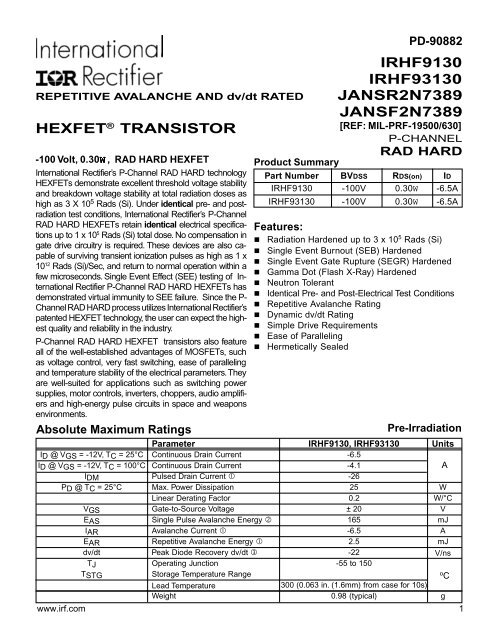
REPETITIVE AVALANCHE AND dv/dt RATEDHEXFET ® <strong>TRANSISTOR</strong>-100 Volt, 0.30W , RAD HARD HEXFETInternational Rectifier’s P-Channel RAD HARD technologyHEXFETs demonstrate excellent threshold voltage stabilityand breakdown voltage stability at total radiation doses ashigh as 3 X 10 5 Rads (Si). Under identical pre- and postradiationtest conditions, International Rectifier’s P-ChannelRAD HARD HEXFETs retain identical electrical specificationsup to 1 x 10 5 Rads (Si) total dose. No compensation ingate drive circuitry is required. These devices are also capableof surviving transient ionization pulses as high as 1 x10 12 Rads (Si)/Sec, and return to normal operation within afew microseconds. Single Event Effect (SEE) testing of InternationalRectifier P-Channel RAD HARD HEXFETs hasdemonstrated virtual immunity to SEE failure. Since the P-Channel RAD HARD process utilizes International Rectifier’spatented HEXFET technology, the user can expect the highestquality and reliability in the industry.P-Channel RAD HARD HEXFET transistors also featureall of the well-established advantages of MOSFETs, suchas voltage control, very fast switching, ease of parallelingand temperature stability of the electrical parameters. Theyare well-suited for applications such as switching powersupplies, motor controls, inverters, choppers, audio amplifiersand high-energy pulse circuits in space and weaponsenvironments.Absolute Maximum RatingsPD-90882<strong>IRHF9130</strong>IRHF93130<strong>JANSR2N7389</strong><strong>JANSF2N7389</strong>[REF: MIL-PRF-19500/630]P-CHANNELRAD HARDProduct SummaryPart Number BVDSS RDS(on) ID<strong>IRHF9130</strong> -100V 0.30W -6.5AIRHF93130 -100V 0.30W -6.5AFeatures:n Radiation Hardened up to 3 x 10 5 Rads (Si)n Single Event Burnout (SEB) Hardenedn Single Event Gate Rupture (SEGR) Hardenedn Gamma Dot (Flash X-Ray) Hardenedn Neutron Tolerantn Identical Pre- and Post-Electrical Test Conditionsn Repetitive Avalanche Ratingn Dynamic dv/dt Ratingn Simple Drive Requirementsn Ease of Parallelingn Hermetically SealedPre-IrradiationParameter <strong>IRHF9130</strong>, IRHF93130 UnitsID @ VGS = -12V, TC = 25°C Continuous Drain Current -6.5ID @ VGS = -12V, TC = 100°C Continuous Drain Current -4.1AIDM Pulsed Drain Current -26PD @ TC = 25°C Max. Power Dissipation 25 WLinear Derating Factor 0.2 W/°CVGS Gate-to-Source Voltage ± 20 VEAS Single Pulse Avalanche Energy ‚ 165 mJIAR Avalanche Current -6.5 AEAR Repetitive Avalanche Energy 2.5 mJdv/dt Peak Diode Recovery dv/dt ƒ -22 V/nsTJ Operating Junction -55 to 150TSTGStorage Temperature RangeLead Temperature 300 (0.063 in. (1.6mm) from case for 10s)o CWeight 0.98 (typical) gwww.irf.com 1
REVIEW ONLY<strong>IRHF9130</strong>, IRHF93130, JANSR-, JANSF-, 2N7389 DevicePre-IrradiationElectrical Characteristics @ Tj = 25°C (Unless Otherwise Specified)Parameter Min Typ Max Units Test ConditionsBVDSS Drain-to-Source Breakdown Voltage -100 — — V VGS =0 V, ID = -1.0mADBVDSS/DTJ Temperature Coefficient of Breakdown — -0.112 — V/°C Reference to 25°C, ID = -1.0mAVoltageRDS(on) Static Drain-to-Source — — 0.30 VGS = -12V, ID = -4.1A „On-State Resistance — — 0.35 W VGS = -12V, ID = -6.5AVGS(th) Gate Threshold Voltage -2.0 — -4.0 V VDS = VGS, ID = -1.0mAgfs Forward Transconductance 2.5 — — S ( ) VDS > -15V, IDS = -4.1A „IDSS Zero Gate Voltage Drain Current — — -25 VDS= 0.8 x Max Rating,VGS=0VmA— — -250 VDS = 0.8 x Max RatingVGS = 0V, TJ = 125°CIGSS Gate-to-Source Leakage Forward — — -100 VGS = -20VnAIGSS Gate-to-Source Leakage Reverse — — 100 VGS = 20VQg Total Gate Charge — — 45 VGS = -12V, ID = -6.5AQgs Gate-to-Source Charge — — 10 nC VDS = Max Rating x 0.5Qgd Gate-to-Drain (‘Miller’) Charge — — 25td(on) Turn-On Delay Time — — 30 VDD = -50V, ID = -6.5A,tr Rise Time — — 50 RG = 7.5Wnstd(off) Turn-Off Delay Time — — 70tf Fall Time — — 70LD Internal Drain Inductance — 5.0 —LS Internal Source Inductance — 13 —nHWMeasured from drain lead,6mm (0.25 in) from packageto center of die.Measured from source lead,6mm (0.25 in) from packageto source bonding pad.Modified MOSFET symbol showingthe internal inductances.Ciss Input Capacitance — 1200 — VGS = 0V, VDS = -25VCoss Output Capacitance — 290 — pF f = 1.0MHzCrss Reverse Transfer Capacitance — 76 —Source-Drain Diode Ratings and CharacteristicsParameter Min Typ Max Units Test ConditionsIS Continuous Source Current (Body Diode) — — -6.5 Modified MOSFET symbol showing the integralAISM Pulse Source Current (Body Diode) — — -26 reverse p-n junction rectifier.VSD Diode Forward Voltage — — -3.0 V Tj = 25°C, IS = -6.5A, VGS = 0V „trr Reverse Recovery Time — — 250 ns Tj = 25°C, IF = -6.5A, di/dt £ -100A/msQRR Reverse Recovery Charge — — 0.74 mC VDD £ -50V „ton Forward Turn-On Time Intrinsic turn-on time is negligible. Turn-on speed is substantially controlled by LS + LD.Thermal ResistanceParameter Min Typ Max Units Test ConditionsRthJC Junction-to-Case — — 5.0°C/WRthJA Junction-to-Ambient — 175 — Typical socket mount2 www.irf.com
REVEW ONLY<strong>IRHF9130</strong>, IRHF93130, JANSR-, JANSF-, 2N7389 DeviceRadiation CharacteristicsRadiation Performance of P-Channel RadHard HEXFETsInternational Rectifier Radiation Hardened HEXFETsare tested to verify their hardness capability. The hardnessassurance program at International Rectifier comprisesthree radiation environments.Every manufacturing lot is tested in a low dose rate(total dose) environment per MIL-STD-750, test method1019 condition A. International Rectifier has imposeda standard gate condition of -12 volts per note 5 and aV DSbias condition equal to 80% of the device ratedvoltage per note 6. Pre- and post- irradiation limits ofthe devices irradiated to 1 x 10 5 Rads (Si) are identicaland are presented in Table 1, column 1, <strong>IRHF9130</strong>.Post-irradiation limits of the devices irradiated to 3 x10 5 Rads (Si) are presented in Table 1, column 2,IRHF93130. The values in Table 1 will be met for eitherof the two low dose rate test circuits that are used.Both pre- and post-irradiation performance are testedand specified using the same drive circuitry and testconditions in order to provide a direct comparison. Itshould be noted that at a radiation level of 3 x 10 5Rads (Si) the only parametric limit change is V GS(th)maximum.High dose rate testing may be done on a special requestbasis using a dose rate up to 1 x 10 12 Rads (Si)/Sec (See Table 2).International Rectifier radiation hardened P-ChannelHEXFETs are considered to be neutron-tolerant, asstated in MIL-PRF-19500 Group D. International Rectifierradiation hardened P-Channel HEXFETs havebeen characterized in heavy ion Single Event Effects(SEE) environments. Single Event Effects characterizationis shown in Table 3.Table 1. Low Dose Rate … † <strong>IRHF9130</strong> IRHF93130Parameter 100K Rads (Si) 300K Rads (Si) Units Test Conditions ˆMIN MAX MIN MAXBV DSS Drain-to-Source Breakdown Voltage -100 — -100 — V V GS = 0V, I D = -1.0mAVGS(th) Gate Threshold Voltage „ -2.0 -4.0 -2.0 -5.0 VGS = V DS , I D = -1.0mAI GSS Gate-to-Source Leakage Forward — -100 — -100 nA V GS = -20VI GSS Gate-to-Source Leakage Reverse — 100 — 100 V GS = 20VI DSS Zero Gate Voltage Drain Current — -25 — -25 µA V DS =0.8 x Max Rating, V GS =0VR DS(on)1 Static Drain-to-Source „ — 0.30 — 0.30 W VGS = -12V, I D =-4.1AOn-State Resistance OneV SD Diode Forward Voltage „ — -3.0 — -3.0 V TC = 25°C, IS = -6.5A,V GS = 0VTable 2. High Dose Rate ‡10 11 Rads (Si)/sec 10 12 Rads (Si)/secParameter Min Typ Max Min Typ Max Units Test ConditionsV DSS Drain-to-Source Voltage — — -80 — — -80 V Applied drain-to-source voltage duringgamma-dotIPP — -60 — — -60 — A Peak radiation induced photo-currentdi/dt — — -800 — — -160 A/µsec Rate of rise of photo-currentL1 0.1 — — 0.5 — — µH Circuit inductance required to limit di/dtTable 3. Single Event EffectsLET (Si) Fluence Range V DS Bias V GS BiasIon(MeV/mg/cm 2 ) (ions/cm 2 ) (µm) (V) (V)Cu 28 3x 10 5 ~43 -100 5www.irf.com 3
REVIEW ONLY<strong>IRHF9130</strong>, IRHF93130, JANSR-, JANSF-, 2N7389 DevicePre-Irradiation-I D , Drain-to-Source Current (A)10010VGSTOP -15V-12V-10V-9.0V-8.0V-7.0V-6.0VBOTTOM -5.0V-5.0V20µs PULSE WIDTHT J = 25 ° C11 10 100-V DS , Drain-to-Source Voltage (V)-I D , Drain-to-Source Current (A)10010VGSTOP -15V-12V-10V-9.0V-8.0V-7.0V-6.0VBOTTOM -5.0V-5.0V20µs PULSE WIDTHT J = 150 ° C11 10 100-V DS , Drain-to-Source Voltage (V)Fig 1. Typical Output CharacteristicsFig 2. Typical Output Characteristics-I D , Drain-to-Source Current (A)10010T J = 25 ° CT J = 150 ° CV DS= -50V20µs PULSE WIDTH15 6 7 8 9 10-V GS , Gate-to-Source Voltage (V)R DS(on) , Drain-to-Source On Resistance(Normalized)2.5I D = -6.5A2.01.51.00.5V GS = -12V0.0-60 -40 -20 0 20 40 60 80 100 120 140 160T J , Junction Temperature( ° C)Fig 3. Typical Transfer CharacteristicsFig 4. Normalized On-ResistanceVs. Temperature4 www.irf.com
REVEW ONLY<strong>IRHF9130</strong>, IRHF93130, JANSR-, JANSF-, 2N7389 DevicePre-IrradiationC, Capacitance (pF)2000VGS= 0V, f = 1MHzCiss = Cgs + Cgd , C ds SHORTEDCrss= CgdCoss = Cds + Cgd1500C iss1000C oss500C rss01 10 100-V DS , Drain-to-Source Voltage (V)-V GS , Gate-to-Source Voltage (V)20161284I = D-6.5AV DS =-80VV DS =-50VV DS =-20VFOR TEST CIRCUITSEE FIGURE 1300 10 20 30 40 50 60Q G , Total Gate Charge (nC)Fig 5. Typical Capacitance Vs.Drain-to-Source VoltageFig 6. Typical Gate Charge Vs.Gate-to-Source Voltage-I SD , Reverse Drain Current (A)100101T J = 150 ° CT J = 25 ° CV GS = 0 V0.10.2 1.0 1.8 2.6 3.4 4.2-V SD ,Source-to-Drain Voltage (V)-I I D , Drain Current (A)10010OPERATION IN THIS AREA LIMITEDBY R DS(on)100us1msTC= 25 ° CTJ= 150 ° CSingle Pulse10ms11 10 100 1000-V DS , Drain-to-Source Voltage (V)Fig 7. Typical Source-Drain DiodeFig 8. Maximum Safe Operating AreaForward Voltagewww.irf.com 5
REVIEW ONLY<strong>IRHF9130</strong>, IRHF93130, JANSR-, JANSF-, 2N7389 DevicePre-Irradiation7.0V DSR D-I D , Drain Current (A)6.05.04.03.02.01.00.025 50 75 100 125 150T C , Case Temperature ( ° C)Fig 9. Maximum Drain Current Vs.Case TemperatureR GV GS-12VPulse Width £1 µsDuty Factor £ 0.1 %D.U.T.Fig 10a. Switching Time Test CircuitV GSt d(on) t r t d(off) t f10%90%V DSFig 10b. Switching Time Waveforms+-V DD10Thermal Response (Z thJC )10.10.500.200.100.050.020.01SINGLE PULSE(THERMAL RESPONSE)Notes:1. Duty factor D = t 1 / t 22. Peak T J = P DM x Z thJC + TC0.010.00001 0.0001 0.001 0.01 0.1 1 10t 1, Rectangular Pulse Duration (sec)PDMt1t2Fig 11. Maximum Effective Transient Thermal Impedance, Junction-to-Case6 www.irf.com
REVEW ONLY<strong>IRHF9130</strong>, IRHF93130, JANSR-, JANSF-, 2N7389 DevicePre-IrradiationV LDSR GD.U.TV DDI ASA-12V -20VDRIVERtp 0.01Ω15VI ASFig 12a. Unclamped Inductive Test CircuitE AS , Single Pulse Avalanche Energy (mJ)400300200100I DTOP -2.9A-4.1ABOTTOM -6.5A025 50 75 100 125 150Starting T , Junction Temperature( °JC)tpFig 12c. Maximum Avalanche EnergyVs. Drain CurrentV (BR)DSSFig 12b. Unclamped Inductive WaveformsCurrent RegulatorSame Type as D.U.T.-12VQ G-12V.2µF50KΩ.3µFQ GSQ GDD.U.T.+V DS-V GV GS-3mAChargeI G I DCurrent Sampling ResistorsFig 13a. Basic Gate Charge WaveformFig 13b. Gate Charge Test Circuitwww.irf.com 7
REVIEW ONLY<strong>IRHF9130</strong>, IRHF93130, JANSR-, JANSF-, 2N7389 DevicePre-IrradiationRepetitive Rating; Pulse width limited bymaximum junction temperature.Refer to current HEXFET reliability report.‚ @ VDD = -25V, Starting TJ = 25°C,EAS = [0.5 * L * (IL 2 ) ]Peak IL = -6.5A, VGS = -12V, 25 £ RG £ 200Wƒ ISD £ -6.5A, di/dt £ -430A/ms,VDD £ BVDSS, TJ £ 150°CSuggested RG = 7.5W„ Pulse width £ 300 ms; Duty Cycle £ 2%… Total Dose Irradiation with VGS Bias.-12 volt VGS applied and VDS = 0 duringirradiation per MIL-STD-750, method 1019.† Total Dose Irradiation with VDS Bias.VDS = 0.8 rated BVDSS (pre-radiation)applied and VGS = 0 during irradiation perMlL-STD-750, method 1019.‡ This test is performed using a flash x-raysource operated in the e-beam mode (energy~2.5 MeV), 30 nsec pulse.ˆ All Pre-Radiation and Post-Radiation testconditions are identical to facilitate directcomparison for circuit applications.Case Outline and Dimensions — TO-205AF (Modified TO-39)All dimensions are shown millimeters (inches)WORLD HEADQUARTERS: 233 Kansas St., El Segundo, California 90245, Tel: (310) 322 3331IR GREAT BRITAIN: Hurst Green, Oxted, Surrey RH8 9BB, UK Tel: ++ 44 1883 732020IR CANADA: 15 Lincoln Court, Brampton, Ontario L6T3Z2, Tel: (905) 453 2200IR GERMANY: Saalburgstrasse 157, 61350 Bad Homburg Tel: ++ 49 6172 96590IR ITALY: Via Liguria 49, 10071 Borgaro, Torino Tel: ++ 39 11 451 0111IR FAR EAST: K&H Bldg., 2F, 30-4 Nishi-Ikebukuro 3-Chome, Toshima-Ku, Tokyo Japan 171 Tel: 81 3 3983 0086IR SOUTHEAST ASIA: 1 Kim Seng Promenade, Great World City West Tower, 13-11, Singapore 237994 Tel: ++ 65 838 4630IR TAIWAN:16 Fl. Suite D. 207, Sec. 2, Tun Haw South Road, Taipei, 10673, Taiwan Tel: 886-2-2377-9936http://www.irf.com/ Data and specifications subject to change without notice. 8/988 www.irf.com


