kit 400/400w â 500/500w standard, processor ... - KÃHTREIBER sro
kit 400/400w â 500/500w standard, processor ... - KÃHTREIBER sro
kit 400/400w â 500/500w standard, processor ... - KÃHTREIBER sro
- No tags were found...

Create successful ePaper yourself
Turn your PDF publications into a flip-book with our unique Google optimized e-Paper software.
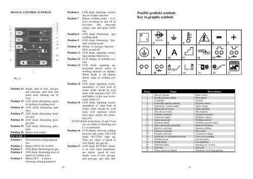
DIGITAL CONTROL SYNERGICPic. CPosition 14 feeder, start of wire, pre-gasand post-gas, spot time andpulse time, burning out ofwirePosition 15 LED diode illustrating speedof shifting of welding wirePosition 16 LED diode illustrating spottimePosition 17 LED diode illustrating burntout timePosition 18 LED diode illustrating postgastimePosition 19 LED diode illustrating pulsetimePosition 20 Button wire feederPICTURE CPosition 1 Potentiometer setting parametersPosition 2 Button TEST OF GASESPosition 3 LED diode illustrating pre-gasPosition 4 LED diode illustrating start ofspeed of welding wirePosition 5 Button SET – it allowschoosing setting parametersPosition 6 LED diode illustrates switchingon of pulse functionPosition 7 Button welding mode – it allowsswitching on and off oftwo-time and four-timemodes, spot and pulse welding.Position 8 LED diode illustrating spotwelding modePosition 9 LED diode illustrating fourtimewelding modePosition 10 Switch of synergic function –SYN on and offPosition 11 LED diode signaling switchingsynergic function onPosition 12 LCD display of welding currentPosition 13 LED diode signaling approximatepower values ofwelding material on display.When diode is off displayshows value of welding current.Position 14 LED diode signaling recommendationof what kind ofchoke outlet should be used(only with machines KIT 255and higher, in this case it concernsoutlet L2)Position 15 LED diode signaling recommendationof what kind ofchoke outlet should be used(only with machines whichhave three outlets for chockingcoil)If LED diodes in positions 14 and 15 arenot on, outlet of chocking coilL1 is connectedPosition 16 LCD display showing weldingpressure and vaules with LEDdiode SETTING light up.They are values of speed ofwire feeder, pre-gas etc.Position 17 LED diode SETTING whichis on only when parametersare shown: speed of wirefeeder, start of wire, pre-gasand post-gas, spot time andPoužité grafické symbolyKey to graphic symbolsPozn. Popis Description1 Hlavní vypínač Main switch2 Rychlost posuvu drátu Wire speed3 Uzemnění Ground4 Kontrolka tepelné ochrany Thermo control5 Nebezpečí, vysoké napětí High voltage6 Mínus pól na svorce Minus polarity7 Plus pól na svorce Plus polarity8 Ochrana zeměním Ground protection9 Svařovací napětí Welding voltage10 Svařovací proud Welding current11 Přepínač napětí Welding current switch12 Síla svařovaného materiálu Material thickness13 Bodové svařování Spoting welding14 Pulsové svařování Puls mode15 Plynulé svařování Continue welding16 Svařování ve čtyřtaktním režimu Four cycle welding17 Předfuk plynu Gas fore-blow18 Dofuk plynu Gas afterblow19 Dohoření drátu Burning out of wire20 Soft start Soft start21 Pozor, točící se soukolí Attention, revolving gearing- 30 -- 43 -